Page 1446 of 2103
AUTOMATIC TRANSAXLE OVERHAUL Transaxle
f r o n t s u n g e a r a s s e m b l y .
Front sun assembly
shaft
Oil
determine the proper thickness thrust
plate, select the thinnest No. 4 “test” thrust plat e; Using,
to hold thrust in position,, install input
clutches assembly. Be sure the ‘input assembly
is completely seated.
Caution
if view through input speed sensor hole is not as
shown above, the input
assembly is not
seated
the oil pump O-ring. You can install and remove
the oil pump and gasket very easily to
No. 4 thrust plate..Caution
Be sure to install O-ring on oil
the proper No. 4 thrust plate.
Temporarily secure oil pump 2 oil bolts.
Insert a bolt into end of input shaft.
Measure input shaft end play.
If end play readings are not within
the transaxle assembly. will be damaged.
.
TSBRevision
Page 1509 of 2103
I
8990767
ON-VEHICLE SERVICE
WHEEL BEARING END PLAY CHECK
1. Remove the disc brake caliper and suspend it with a
wire.
2. Remove the brake disc from the front hub.
3.Attach a dial gauge as shown in the illustration, and then
measure the end play while moving the hub in the ax ial
direction.
Limit: 0.05 mm in.)
4.If end play exceeds the replace the front hub assem-
bly.
HUB BOLT REPLACEMENT
1. Remove the caliper assembly and secure it with w ire
so that it does not fall.
2. Remove the brake disc.
3. Use the special tools to remove the hub bolts.
Caution
Be sure to tie the cord special tool to a nearby
part.
4.Use the wheel nuts to securely install the new hub bolts,
while being careful of the serrations of the hub bo lts and
hub;
TSB Revision
Page 1510 of 2103
26-6FRONT AXLE Front
FRONT HUB ASSEMBLY
REMOVAL AND INSTALLATION
88 Nm65
8885
Removal steps
1. Cotter pin 2. Drive shaft nut
3. Front wheel speed sensor
with 4. Caliper assembly
5. Brake disc
A l
Nut
Nm
145-188
5
Caution
6. Upper
7. Front hub.
The front hub assembly not be disassembled..
REMOVAL SERVICE POINTS
DRIVE SHAFT R E M O V A L .
CALIPER ASSEMBLY REMOVAL
Secure the removed caliper so that it
does not fall., ,
ARM BALL JOINT AND KNUCKLE
DISCONNECTION
Caution
1.Using the tool, loosen the tie rod end mounting
nut. Only loosen the nut; do not remove it from the
joint.
2.Support the tool with a cord, etc. to prevent
it from coming off.
TSB Revision
Page 1511 of 2103

FRONT AXLE Front Hub Assembly
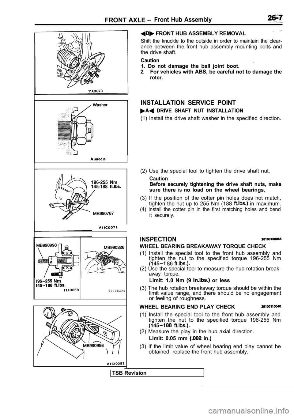
196-255 Nm
145-188
I(2) Use the special tool to tighten the drive shaft nut.
Caution
Before securely tightening the drive shaft nuts, ma ke
sure there isno load on the wheel bearings.
(3) If the position of the cotter pin holes does no t match,
tighten the nut up to 255 Nm (188
in maximum.
(4) Install the cotter pin in the first matching ho les and bend
it securely.
INSPECTION
WHEEL BEARING BREAKAWAY TORQUE CHECK
(1) Install the special tool to the front hub assem bly and
tighten the nut to the specified torque 196-255 Nm
86
(2) Use the special tool to measure the hub rotatio n break-
away torque.
Limit: 1.0 Nm (9 or less
(3) The hub rotation breakaway torque should be wit hin the
limit value range, and there should be no engagemen t
or feeling of roughness. Nm
0 0 0 0 0 3 2 0
FRONT HUB ASSEMBLY REMOVAL
Shift the knuckle to the outside in order to mainta in the clear-
ance between the front hub assembly mounting bolts and
the drive shaft.
Caution
1. Do not damage the ball joint boot.
2.For vehicles with ABS, be careful not to damage the
rotor.
INSTALLATION SERVICE POINT
DRIVE SHAFT NUT INSTALLATION
(1) Install the drive shaft washer in the specified direction.
WHEEL BEARING END PLAY CHECK
(1) Install the special tool to the front hub assem bly and
tighten the nut to the specified torque 196-255 Nm
(2) Measure the play in the hub axial direction.
Limit: 0.05 mm
in.)
(3) If the limit value of wheel bearing end play ca nnot be
obtained, replace the front hub assembly.
TSB Revision
Page 1515 of 2103

FRONT AXLE Drive Shaft
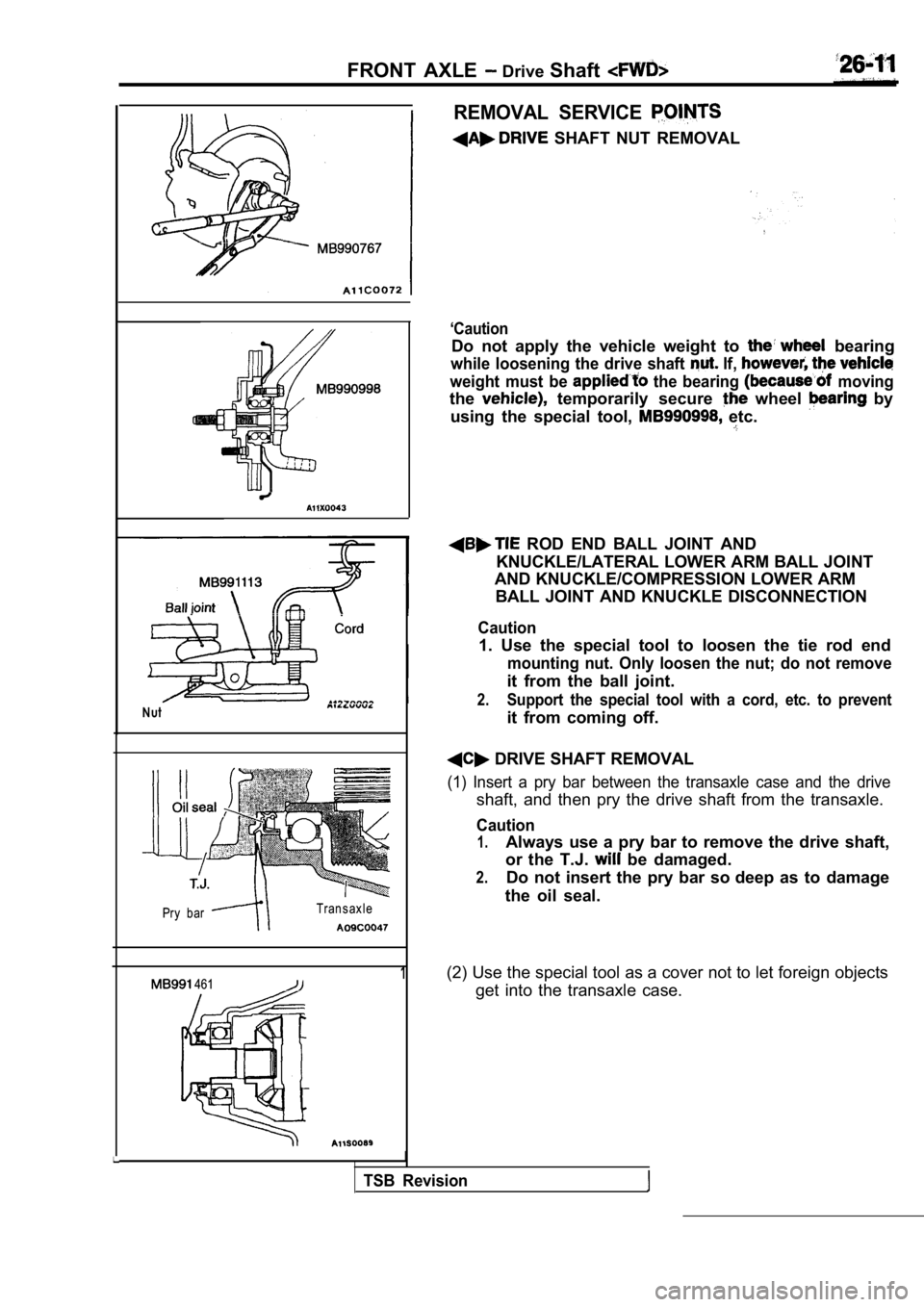
Nut
Pry bar Transaxle
1 461
I
REMOVAL SERVICE
SHAFT NUT REMOVAL
‘Caution
Do not apply the vehicle weight to bearing
while loosening the drive shaft If,
weight must be the bearing moving
the temporarily secure wheel by
using the special tool,
etc.
ROD END BALL JOINT AND
KNUCKLE/LATERAL LOWER ARM BALL JOINT
AND KNUCKLE/COMPRESSION LOWER ARM
BALL JOINT AND KNUCKLE DISCONNECTION
Caution
1. Use the special tool to loosen the tie rod end
mounting nut. Only loosen the nut; do not remove
it from the ball joint.
2.Support the special tool with a cord, etc. to preve nt
it from coming off.
DRIVE SHAFT REMOVAL
(1) Insert a pry bar between the transaxle case and the drive
shaft, and then pry the drive shaft from the transaxle.
Caution
1.Always use a pry bar to remove the drive shaft,
or the T.J.
be damaged.
2.Do not insert the pry bar so deep as to damage
the oil seal.
(2) Use the special tool as a cover not to let fore ign objects
get into the transaxle case.
TSB Revision
Page 1516 of 2103
FRONT AXLE Drive Shaft
88
INSTALLATION SERVICE POINT
DRIVE NUT INSTALLATION
(1) Install the drive shaft washer in the specified
(2) Use the special tool to tighten the drive shaft nut.
Caution
Before securely tightening the drive shaft nuts, ma ke
sure there is no load on the wheel bearings.
(3) If the position of the cotter pin holes,
not match,
tighten the nut up to 255 Nm
‘in maximum.
(4) Install the cotter pin in the first matching ho les and bend
it securely.
INSPECTION
lCheck the drive shaft boot for damage or deteriorat ion.
lCheck the ball joints for wear or, operating condition.
lCheck the spline part for wear or damage.
TSB Revision
Page 1520 of 2103

F R O N T Drive Shaft
561
Stopper
Adjusting bolt
0 0 0 0 3 4 2 0
protruding portion
0 0 0 0 3 4 2 1
0 0 0 0 3 4 2 2(3)
the ajustingbolt of the special tool to adjust the
opening dimension (W) to the standard value.
Standard
2.9 mm in.)
more than 2.9 mm in.)>
Screw in the adjusting bolt.
in.)>
Loosen the adjusting bolt.
NOTE
(1) The dimension (W) is adjusted by approx. 0.7 mm
in.) per one turn.
(2) Do not turn the adjusting bolt more
one turn.
(4) Place the boot band (small) along the protrudin g
and install it so that there is some (A)
the other side. . .
(5) ‘Use the special tool to crimp the B.J. boot
Caution
(1) Hold the drive shaft perpendicularly, and use t he
special tool to crimp the securely.
, (2) Crimp the B.J. boot band until the special to ol
t o u c h e s t h e s t o p p e r .
(6) Check that the crimped width (B) ‘is the
value.
Standard value (B): 2.4 2.8 mm in.)
more than 2.8 mm
Readjust the dimension to the
value calculated by the
and repeat step (5).
5.5 mm in.)
Example: If (B) mm in.), (W) is 2.8
mm
in.).
less than 2.4
Remove the ‘boot band,readjust
dimension (W) of step (3)
calculated by the following equation,
a new B.J. band to
5.5 mm in.)
Example: If is 2.3 is
3.2 m m
TSB Revision
Page 1521 of 2103

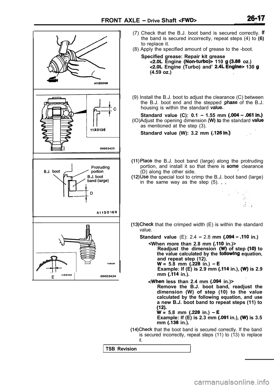
B.J.
FRONT AXLE Drive Shaft
(7) Check that the B.J. boot band is secured correc tly.
the band is secured incorrectly, repeat steps (4) to (6)
to replace it.
(8) Apply the specified amount of grease to the -bo ot.
Specified grease: Repair kit grease
Engine 110 oz.)
Engine (Turbo) and’ 130
(4.59 oz.)
(9) Install the B.J. boot to adjust the clearance ( C) between
the B.J. boot end and the stepped
of the B.J.
housing is within the standard
Standard value (C): 0.1 1.55 mm
(lO)Adjust the opening dimension the standard
as mentioned at the step (3).
Standard value (W): 3.2 mm
the B.J. boot band (large) along the protruding
portion, and install it so that there is
clearance
(D) along the other side.
the special tool to crimp the B.J. boot band (larg e)
in the same way as the step (5). , ,
that the crimped width (E) is within the standard
value.
Standard value (E): 2.4 2.8 mm in.)
in.)>
Readjust the dimension
of step to
the value calculated by the equation,
and repeat step (12).
5.8 mm in.)
Example: If (E) is 2.9 mm in.), is 2.9
mm
in.).
less than 2.4 mm in.)>
Remove the B.J. boot band, readjust the
dimension (W) of step (10) to the value
calculated by the following equation, and use
a new B.J. boot band to repeat steps (11) to
5.8 mm in.)
Example: If (E) is 2.3 mm in.), is 3.5
mm
in.).
that the boot band is secured correctly. If the ba nd
is secured incorrectly, repeat steps (11) to (13) t o replace
it.
TSB Revision