1990 MITSUBISHI SPYDER turn signal
[x] Cancel search: turn signalPage 181 of 2103

ENGINE On-vehicle Service
IDLE MIXTURE CHECK
11100210081
1.Before inspection, set vehicles in the following co ndition:
lEngine coolant temperature:
l Lights, electric cooling fan and all accessories: O FF
lTransaxle: Neutral (P range on vehicles with
2.After turning the ignition switch to OFF, connect t he scan
tool to the data link connector.
3.Start the engine and run it at 2,500 for 2 minutes.
4. Set the CO, HC tester.
5. Check the CO contents and the HC contents at idl e.
Standard value:
CO contents: 0.5% or less
HC contents: 100 ppm or less
6. If the idle speed is outside the standard value, check
the following items: l Diagnostic output
l Closed-loop control (When the closed-loop control
is carried out normally, the output signal of the h eated
oxygen sensor repeats between and
,000 at idle.)
l Fuel pressure
I n j e c t o r
lIgnition coil, spark plug cable, spark plug
lEGR system and the EGR valve leak
l Evaporative emission control system
Compression pressure
NOTE
Replace the three-way catalyst whenever the CO and
HC contents do not remain inside the standard value .
(even though the result of the inspection is normal on
all items.)
COMPRESSION PRESSURE CHECK
1.Before inspection, check that the engine oil, start er and
battery are normal. Also, set the vehicle to the fo llowing
condition:
lEngine coolant temperature:
lLights, electric cooling fan and all accessories: O FF
lTransaxle: Neutral (P range on vehicle with
2. Disconnect the spark plug cables.
3. Remove all spark plugs.
4.Disconnect the relay (ASD relay) connector to prevent
a spark.
4 4
Revision
Page 383 of 2103
ENGINE (NON-TURBO)> General
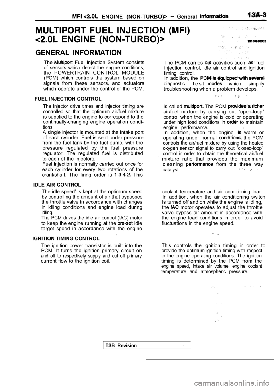
FUEL INJECTION
ENGINE (NON-TURBO)>
GENERAL INFORMATION
The Fuel Injection System consists
of sensors which detect the engine conditions,
the POWERTRAIN CONTROL MODULE(PCM) which controls the system based on
signals from these sensors, and actuators
which operate under the control of the PCM.
FUEL INJECTION CONTROL
The injector drive times and injector timing are
controlled so that the optimum air/fuel mixture
is supplied to the engine to correspond to the
continually-changing engine operation condi-
tions.
A single injector is mounted at the intake port
of each cylinder. Fuel is sent under pressure
from the fuel tank by the fuel pump, with the
pressure regulated by the fuel pressureregulator. The regulated fuel is distributed
to each of the injectors. Fuel injection is normally carried out once for
each cylinder for every two rotations of the
crankshaft. The firing order is
This
IDLE AIR CONTROL The idle speed’ is kept at the optimum speed
by controlling the amount of air that bypasses
the throttle valve in accordance with changes in idling conditions and engine load during
idling.
The PCM drives the idle air control (IAC) motor
to keep the engine running at the idle
target speed in accordance with the engine
IGNITION TIMING CONTROL
The ignition power transistor is built into the
PCM. It turns the ignition primary circuit on
and off to respectively supply and cut off primary
current flow to the ignition coil. The PCM carries
activities such fuel
injection control, idle air control and ignition
timing control.
In addition, the
diagnostict e s twhich simplify
troubleshooting when a problem develops.
is called The PCM
air/fuel mixture by carrying out “open-loop”
control when the engine is cold or operating
under high load conditions in to maintain
engine performance.
In addition, when the engine warm or
operating under normal
the PCM
controls the air/fuel mixture by using the heated
oxygen sensor signal to carry out “closed-loop”
control in order to obtain the theoretical air/fuel
mixture ratio that provides the maximum
cleaning
from the three way
catalyst.
coolant temperature and air conditioning load.
In addition, when the air conditioning switch
is turned off and on while the engine is idling,
the
motor operates to adjust the throttle
valve bypass air amount in accordance with
the engine load conditions in order to avoid
fluctuations in the engine speed.
This controls the ignition timing in order to
provide the optimum ignition timing with respect
to the engine operating conditions. The ignition
timing is determined by the PCM from the
engine speed, intake air volume, engine coolant
temperature and atmospheric pressure.
TSB Revision
Page 384 of 2103
ENGINE (NON-TURBO)>
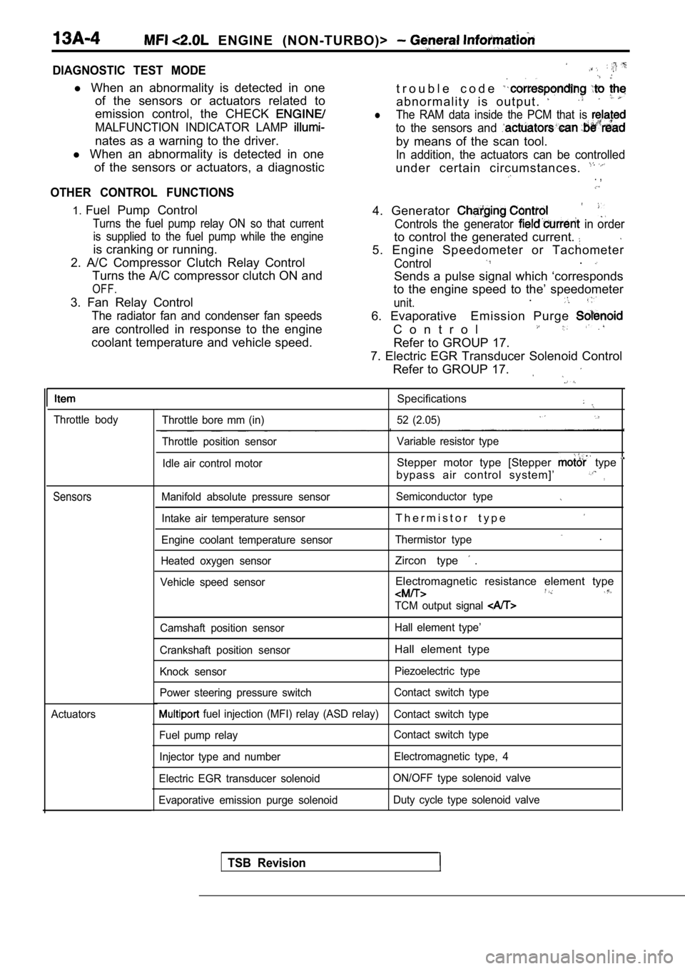
DIAGNOSTIC TEST MODE
l When an abnormality is detected in one
of the sensors or actuators related to
emission control, the CHECK
MALFUNCTION INDICATOR LAMP
nates as a warning to the driver.
l When an abnormality is detected in one
of the sensors or actuators, a diagnostic
OTHER CONTROL FUNCTIONS
t r o u b l e c o d e
a b n o r m a l i t y i s o u t p u t .
lThe RAM data inside the PCM that is
to the sensors and
by means of the scan tool.
In addition, the actuators can be controlled
under certain circumstances. . ,
1. Fuel Pump Control
Turns the fuel pump relay ON so that current
is supplied to the fuel pump while the engine
is cranking or running.
2. A/C Compressor Clutch Relay Control Turns the A/C compressor clutch ON and
OFF.
3. Fan Relay Control
The radiator fan and condenser fan speeds
are controlled in response to the engine
coolant temperature and vehicle speed. 4. Generator
Controls the generator in order
to control the generated current.
5. Engine Speedometer or Tachometer
Control.
Sends a pulse signal which ‘corresponds
to the engine speed to the’ speedometer
unit..
6. Evaporative Emission Purge
C o n t r o l
Refer to GROUP 17.
7. Electric EGR Transducer Solenoid Control Refer to GROUP 17.
Throttle body
Sensors
Actuators
Specifications
Throttle bore mm (in) 52 (2.05)
Throttle position sensor Variable resistor type
Idle air control motor
Stepper motor type [Stepper type
bypass air control system]’,
Manifold absolute pressure sensor Semiconductor type
Intake air temperature sensorT h e r m i s t o r t y p e
Engine coolant temperature sensorThermistor type .
Heated oxygen sensorZircon type .
Vehicle speed sensorElectromagnetic resistance element type
TCM output signal
Camshaft position sensor Hall element type’
Crankshaft position sensor
Hall element type
Knock sensor Piezoelectric type
Power steering pressure switch Contact switch type
fuel injection (MFI) relay (ASD relay)
Contact switch type
Fuel pump relay Contact switch type
Injector type and number Electromagnetic type, 4
Electric EGR transducer solenoid ON/OFF type solenoid valve
Evaporative emission purge solenoid Duty cycle type solenoid valve
TSB Revision
Page 396 of 2103
ENGINE (NON-TURBO)> Troubleshooting
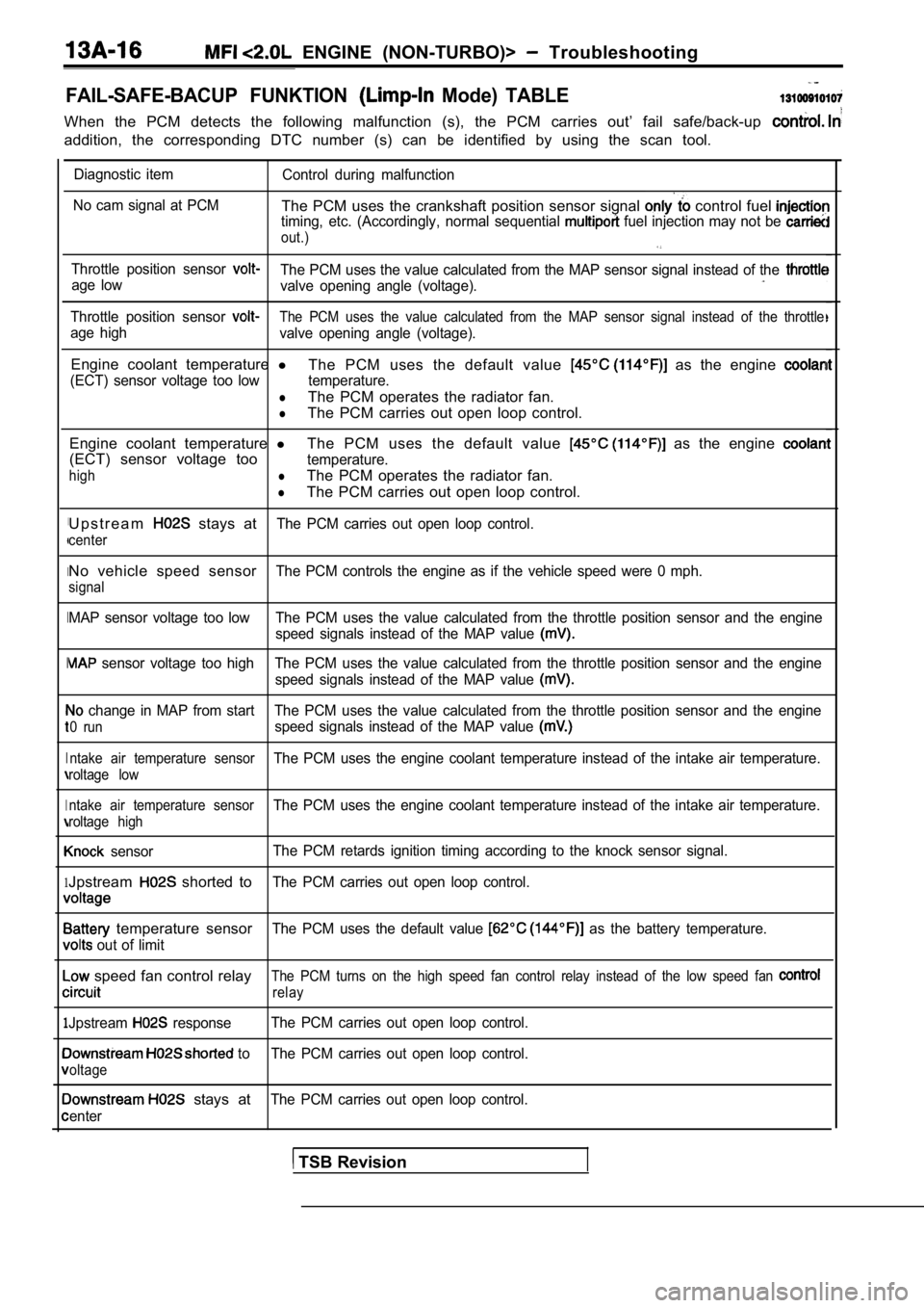
FAIL-SAFE-BACUP FUNKTION Mode) TABLE
When the PCM detects the following malfunction (s), the PCM carries out’ fail safe/back-up
addition, the corresponding DTC number (s) can be i dentified by using the scan tool.
I
I
I
I
I
1
1
Diagnostic item
Control during malfunction
No cam signal at PCM
The PCM uses the crankshaft position sensor signal control fuel timing, etc. (Accordingly, normal sequential fuel injection may not be
out.)
Throttle position sensor The PCM uses the value calculated from the MAP sens or signal instead of the age low
valve opening angle (voltage).
Throttle position sensor The PCM uses the value calculated from the MAP sens or signal instead of the throttle
age high
valve opening angle (voltage).
Engine coolant temperature l
The PCM uses the default value as the engine
(ECT) sensor voltage too low temperature.
lThe PCM operates the radiator fan.
lThe PCM carries out open loop control.
Engine coolant temperature lThe PCM uses the default value
as the engine
(ECT) sensor voltage tootemperature.
highlThe PCM operates the radiator fan.
lThe PCM carries out open loop control.
U p s t r e a m
stays atThe PCM carries out open loop control.
center
No vehicle speed sensorThe PCM controls the engine as if the vehicle speed were 0 mph.
signal
MAP sensor voltage too low The PCM uses the value ca lculated from the throttle position sensor and the engine
speed signals instead of the MAP value
sensor voltage too high The PCM uses the value calc ulated from the throttle position sensor and the engine
speed signals instead of the MAP value
change in MAP from start The PCM uses the value cal culated from the throttle position sensor and the engine
0 runspeed signals instead of the MAP value
ntake air temperature sensorThe PCM uses the engine coolant temperature instead of the intake air temperature.
roltage low
ntake air temperature sensor
The PCM uses the engine coolant temperature instead of the intake air temperature.
roltage high
sensorThe PCM retards ignition timing according to the kn
ock sensor signal.
Jpstream shorted toThe PCM carries out open loop control.
temperature sensorThe PCM uses the default value as the battery temperature.
out of limit
speed fan control relayThe PCM turns on the high speed fan control relay i nstead of the low speed fan
relay
Jpstream responseThe PCM carries out open loop control.
to The PCM carries out open loop control.
oltage
stays atThe PCM carries out open loop control.
enter
TSB Revision
Page 397 of 2103
ENGINE (NON-TURBO)> Troubleshooting
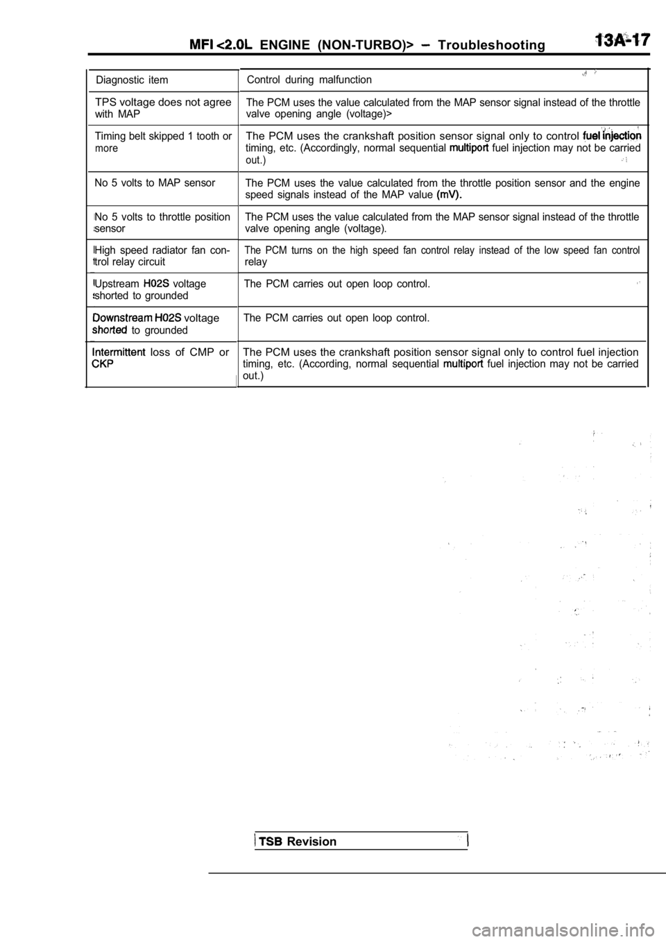
Diagnostic item
TPS voltage does not agree
with MAP
Timing belt skipped 1 tooth or
more
No 5 volts to MAP sensor
No 5 volts to throttle position
sensor
High speed radiator fan con-
trol relay circuit
Upstream
voltage
shorted to grounded
voltage
to grounded
loss of CMP or
Control during malfunction
The PCM uses the value calculated from the MAP sens or signal instead of the throttle
valve opening angle (voltage)>
The PCM uses the crankshaft position sensor signal only to control
timing, etc. (Accordingly, normal sequential fuel injection may not be carried
out.)
The PCM uses the value calculated from the throttle position sensor and the engine
speed signals instead of the MAP value
The PCM uses the value calculated from the MAP sens or signal instead of the throttle
valve opening angle (voltage).
The PCM turns on the high speed fan control relay i nstead of the low speed fan control
relay
The PCM carries out open loop control.
The PCM carries out open loop control.
The PCM uses the crankshaft position sensor signal only to control fuel injection
timing, etc. (According, normal sequential fuel injection may not be carried
out.)
Revision
Page 424 of 2103
![MITSUBISHI SPYDER 1990 Service Repair Manual ENGINE (NON-TURBO)>
Scan tool 40
Code General scan tool No Crank Reference at
No.PCM
11
[Comment]
Background
lThe crankshaft position sensor is a Hall-effect sensor that prov MITSUBISHI SPYDER 1990 Service Repair Manual ENGINE (NON-TURBO)>
Scan tool 40
Code General scan tool No Crank Reference at
No.PCM
11
[Comment]
Background
lThe crankshaft position sensor is a Hall-effect sensor that prov](/manual-img/19/57345/w960_57345-423.png)
ENGINE (NON-TURBO)>
Scan tool 40
Code General scan tool No Crank Reference at
No.PCM
11
[Comment]
Background
lThe crankshaft position sensor is a Hall-effect sensor that provides a voltage signal to
the PCM.
l Voltage alternates between 0 and 5 volts as the cra nkshaft turns.
lThis DTC would indicate a failure of the sensoror its circuit.
Range of Check
l The test is run at start-up.
l Camshaft position sensor indicates that the camshaf t is rotating.
Set Condition
l Crankshaft position sensor signal (High or Low) is not input.
Probable cause
l Open or shorted supply circuit
l Open sensor ground
l Open or shorted signal circuit lExcessive clearance between the sensor androtor Sensor failed l PCM failed
Check the
position sensor.
OK
Measure at the crankshaft position sensor connector lDisconnect the connector, and measure at the harness side.
l Voltage between 1 and ground
(Ignition switch: ON)
O K :
l Continuity between 2 and ground
OK: Continuity
l Voltage between 3 and ground
OK: 4.8-5.2
OK
Check following connectors:
Check the harness wire between the PCM and cranksha ft positionsensor connector.
Replace the PCM.Repair
Check the following
Check trouble symptom.
OK
NG Repair
1
Replace the crankshaft position sensor.
NG
Check trouble symptom.
N G
Replace the PCM.
TSB Revision1
Page 494 of 2103
ENGINE (NON-TURBO)> Troubleshooting
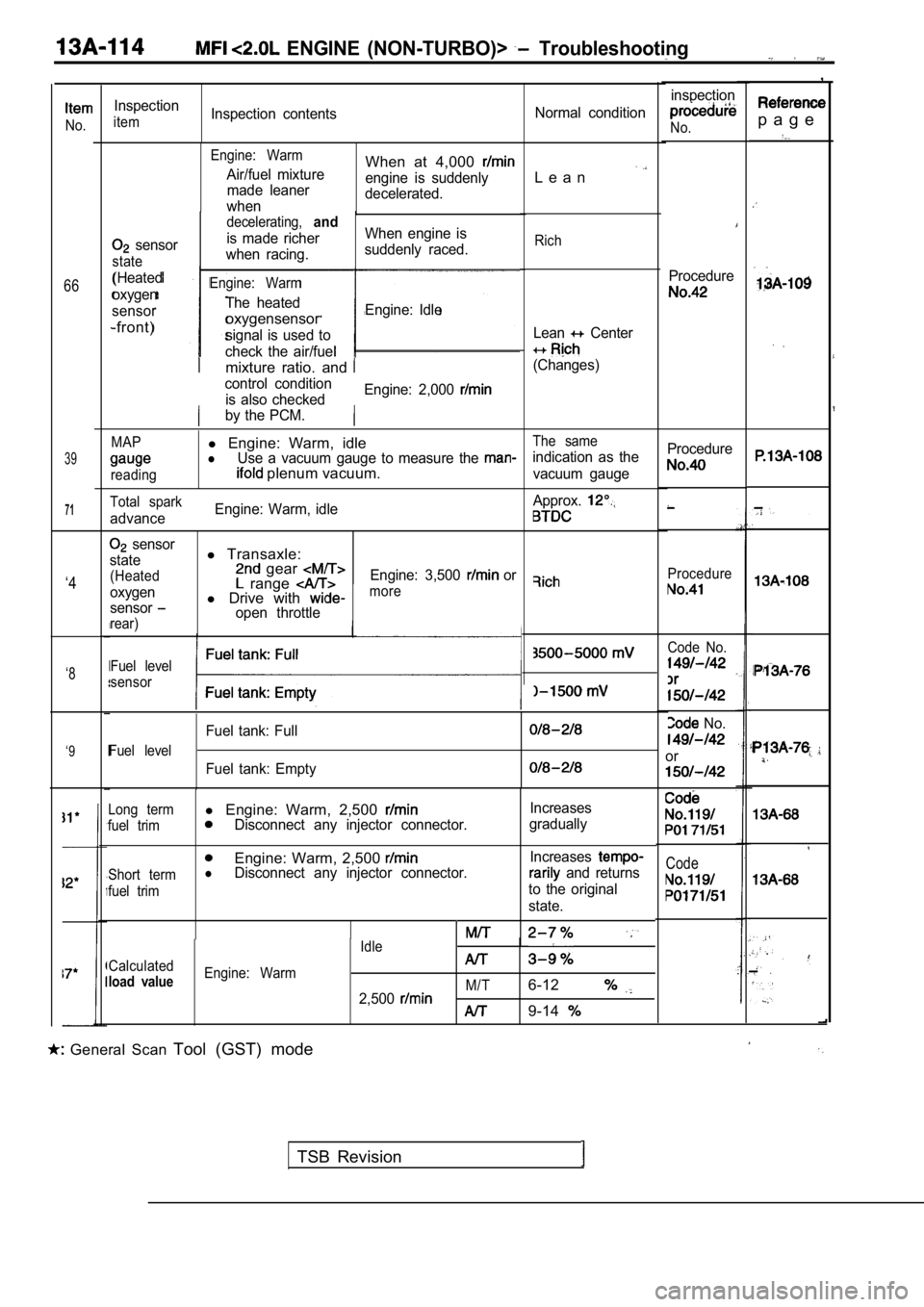
,
p a g eNo.
66
39
71
inspection
No.
Procedure
Inspection
itemInspection contentsNormal condition
Engine: Warm
Air/fuel mixture
made leaner
whenWhen at 4,000
engine is suddenly
decelerated.L e a n
sensor
state
(Heated
oxygen
sensor
-front)
decelerating,and
is made richer When engine is
when racing. suddenly raced.
Engine: Warm
The heated
oxygensensorEngine: Idle
signal is used to
check the air/fuel
Rich
Lean Center
(Changes)mixture ratio. and
control condition is also checked Engine: 2,000
by the PCM.
MAPl
Engine: Warm, idleThe same
lUse a vacuum gauge to measure the indication as the
reading plenum vacuum.vacuum gauge Procedure
Procedure
Total spark
advance
Engine: Warm, idle
Approx.
sensor
state
(Heated
oxygen
sensor
rear)
l Transaxle: gear range l Drive with open throttle Engine: 3,500
or‘4more
Code No.
No.
or
Fuel level
sensor‘8
Fuel level
Fuel tank: Full
Fuel tank: Empty
‘9
Code
Long terml
Engine: Warm, 2,500 Increases
fuel trimDisconnect any injector connector. gradually
Engine: Warm, 2,500
Short termlDisconnect any injector connector. Increases and returns
fuel trimto the original
state.
Idle
Calculated
load valueEngine: Warm M/T
2,5006-12
9-14
General Scan Tool (GST) mode
TSB Revision
Page 518 of 2103
ENGINE
AND ENGINE> G e n e r a l
ENGINE (TURBO) AND ENGINE>13199910319
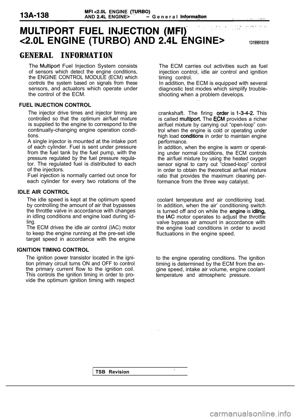
GENERAL INFORMATIONThe
Fuel Injection System consists
of sensors which detect the engine conditions,
the ENGINE CONTROL MODULE (ECM) which
controls the system based on signals from these
sensors, and actuators which operate under
the control of the ECM.
FUEL INJECTION CONTROL
The injector drive times and injector timing are
controlled so that the optimum air/fuel mixture
is supplied to the engine to correspond to the
continually-changing engine operation condi-
tions.
A single injector is mounted at the intake port
of each cylinder. Fuel is sent under pressure
from the fuel tank by the fuel pump, with the
pressure regulated by the fuel pressure regula-
tor. The regulated fuel is distributed to each
of the injectors.
Fuel injection is normally carried out once for
each cylinder for every two rotations of the
IDLE AIR CONTROL The idle speed is kept at the optimum speed
by controlling the amount of air that bypasses
the throttle valve in accordance with changes
in idling conditions and engine load during id-
ling.
The ECM drives the idle air control (IAC) motor
to keep the engine running at the pre-set idle
target speed in accordance with the engine
IGNITION TIMING CONTROL
The ignition power transistor located in the igni-
tion primary circuit turns ON and OFF to control
the primary current flow to the ignition coil.
This controls the ignition timing in order to pro-
vide the optimum ignition timing with respect The ECM carries out activities such as fuel
injection control, idle air control and ignition
timing control.
In addition, the ECM is equipped with several
diagnostic test modes which simplify trouble-
shooting when a problem develops.
. .
crankshaft. The firing is This
is called
The provides a richer
air/fuel mixture by carrying out “open-loop” con-
trol when the engine is cold or operating under high load
in order to maintain engine
performance. In addition, when the engine is warm or operat-
ing under normal conditions, the ECM controls
the air/fuel mixture by using the heated oxygen
sensor signal to carry out “closed-loop” control
in order to obtain the theoretical air/fuel mixture
ratio that provides the maximum cleaning per-
formance from the three way catalyst.
coolant temperature and air conditioning load.
In addition, when the air’ conditioning switch
is turned off and on while the
is
the motor operates to adjust the throttle
valve bypass air amount in accordance with
the engine load conditions in order to avoid
fluctuations in the engine speed.
to the engine operating conditions. The ignition
timing is determined by the ECM from the en-
gine speed, intake air volume, engine coolant
temperature and atmospheric pressure.
TSB Revision