1990 MITSUBISHI SPYDER ABS
[x] Cancel search: ABSPage 5 of 2103
GENERAL How to Use This
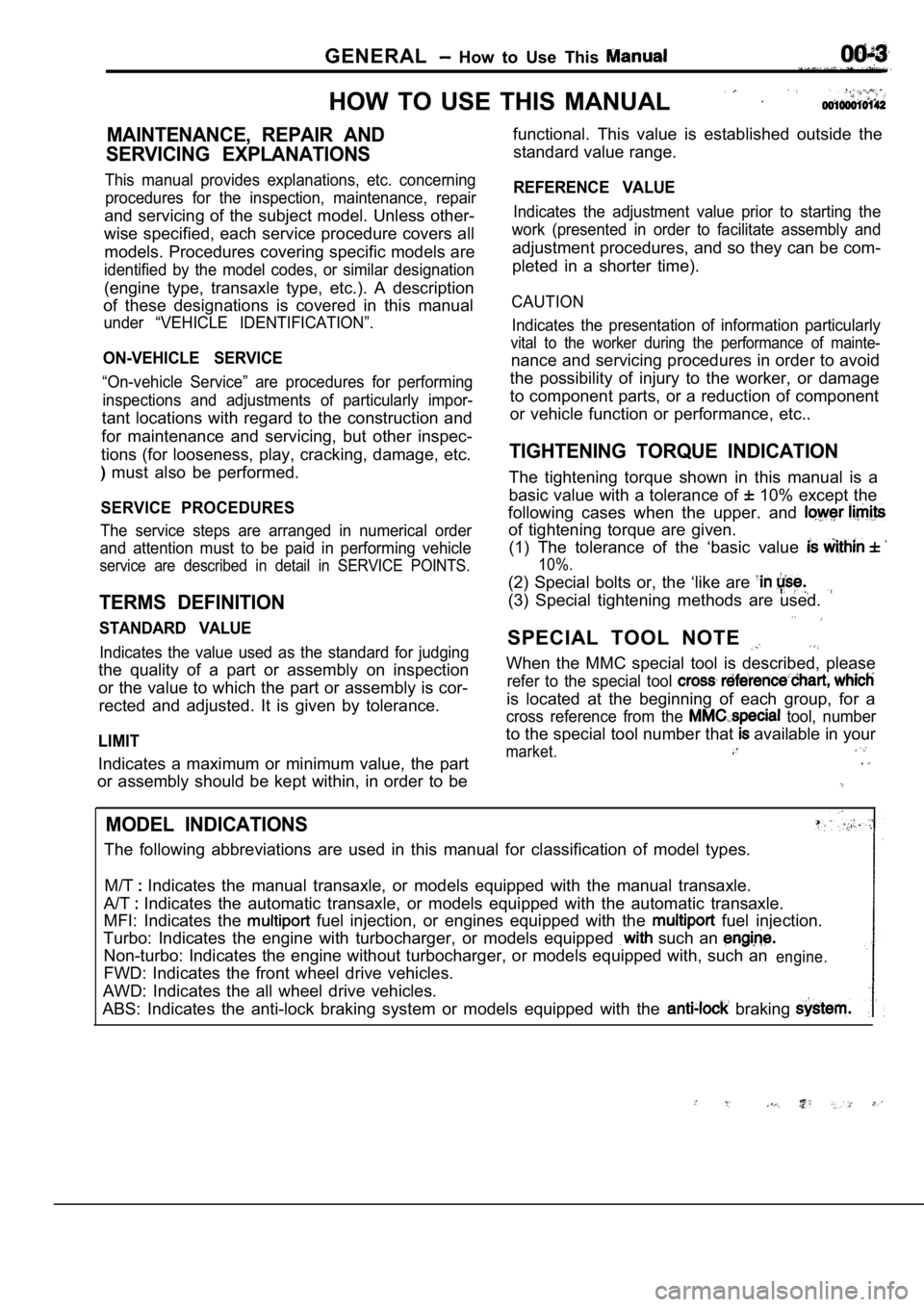
HOW TO USE THIS MANUAL
MAINTENANCE, REPAIR AND
SERVICING EXPLANATIONS
This manual provides explanations, etc. concerning procedures for the inspection, maintenance, repair
and servicing of the subject model. Unless other-
wise specified, each service procedure covers all
models. Procedures covering specific models are
identified by the model codes, or similar designati on
(engine type, transaxle type, etc.). A description
of these designations is covered in this manual
under “VEHICLE IDENTIFICATION”.
ON-VEHICLE SERVICE
“On-vehicle Service” are procedures for performing
inspections and adjustments of particularly impor-
tant locations with regard to the construction and
for maintenance and servicing, but other inspec-
tions (for looseness, play, cracking, damage, etc.
must also be performed.
SERVICE PROCEDURES
The service steps are arranged in numerical order
and attention must to be paid in performing vehicle
service are described in detail in SERVICE POINTS.
TERMS DEFINITION
STANDARD VALUE
Indicates the value used as the standard for judgin g
the quality of a part or assembly on inspection
or the value to which the part or assembly is cor-
rected and adjusted. It is given by tolerance.
LIMIT
Indicates a maximum or minimum value, the part
or assembly should be kept within, in order to be functional. This value is established outside the
standard value range.
REFERENCE VALUE
Indicates the adjustment value prior to starting th e
work (presented in order to facilitate assembly and
adjustment procedures, and so they can be com-
pleted in a shorter time).
CAUTION
Indicates the presentation of information particula rly
vital to the worker during the performance of maint e-
nance and servicing procedures in order to avoid
the possibility of injury to the worker, or damage
to component parts, or a reduction of component
or vehicle function or performance, etc..
TIGHTENING TORQUE INDICATION
The tightening torque shown in this manual is a
basic value with a tolerance of
10% except the
following cases when the upper. and
of tightening torque are given. (1) The tolerance of the ‘basic value
10%.
(2) Special bolts or, the ‘like are
(3) Special tightening methods are used.
SPECIAL TOOL NOTE
When the MMC special tool is described, please
refer to the special tool
is located at the beginning of each group, for a
cross reference from the tool, number
to the special tool number that available in your
market..
MODEL INDICATIONS
The following abbreviations are used in this manual for classification of model types.
M/T
Indicates the manual transaxle, or models equipped with the manual transaxle.
A/T
Indicates the automatic transaxle, or models equip ped with the automatic transaxle.
MFI: Indicates the
fuel injection, or engines equipped with the fuel injection.
Turbo: Indicates the engine with turbocharger, or m odels equipped
such an
Non-turbo: Indicates the engine without turbocharger, or models equipped with, such anengine.
FWD: Indicates the front wheel drive vehicles.
AWD: Indicates the all wheel drive vehicles.
ABS: Indicates the anti-lock braking system or mode ls equipped with the
braking
Page 58 of 2103
GENERAL Main Sealant and Adhesive Table
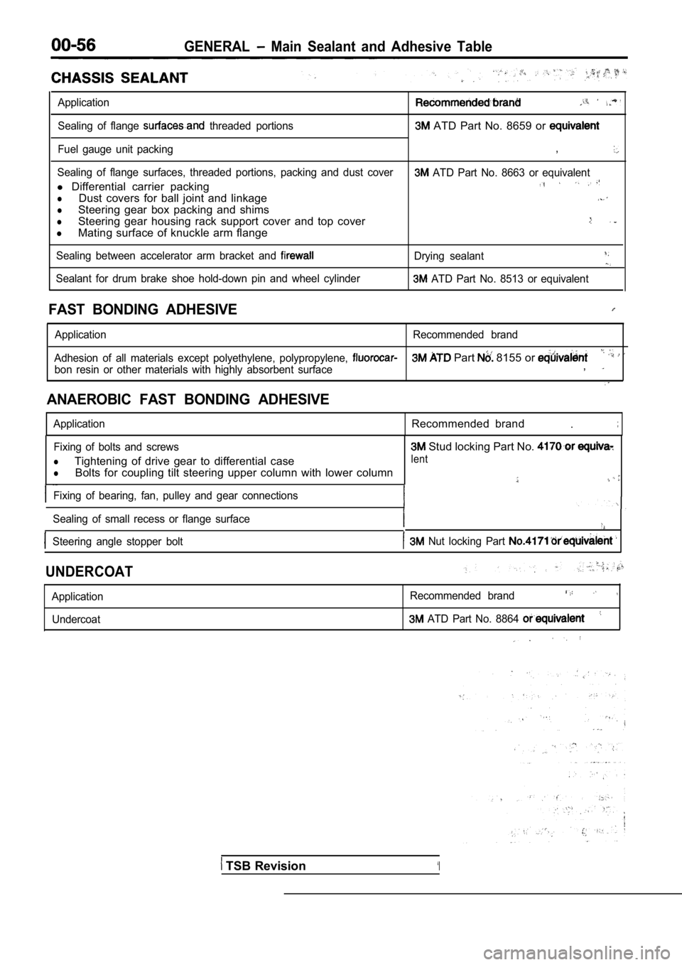
Application
Sealing of flange threaded portions ATD Part No. 8659 or
Fuel gauge unit packing,
Sealing of flange surfaces, threaded portions, packing and dust cover ATD Part No. 8663 or equivalent
l Differential carrier packing
lDust covers for ball joint and linkage
lSteering gear box packing and shims
lSteering gear housing rack support cover and top co ver
lMating surface of knuckle arm flange
Sealing between accelerator arm bracket and Drying sealant
Sealant for drum brake shoe hold-down pin and wheel cylinder ATD Part No. 8513 or equivalent
FAST BONDING ADHESIVE
Application Recommended brand
Adhesion of all materials except polyethylene, poly propylene,
Part 8155 or
bon resin or other materials with highly absorbent surface,
ANAEROBIC FAST BONDING ADHESIVE
ApplicationRecommended brand.
Fixing of bolts and screws
lTightening of drive gear to differential case
lBolts for coupling tilt steering upper column with lower column
Fixing of bearing, fan, pulley and gear connections
Sealing of small recess or flange surface
Steering angle stopper bolt Nut locking Part
Stud locking Part No.
lent
UNDERCOAT
Application Undercoat Recommended brand
ATD Part No. 8864
TSB Revision‘I
Page 213 of 2103

ENGINE OVERHAUL
Items
Engine coolant temperature sensor
Fuel and emission control parts
EGR tube
EGR valve
Intake manifold
11 8
Intake manifold air temperature sensor
Manifold absolute pressure sensor
Intake manifold
Exhaust manifold
Exhaust manifold
Camshaft and cam follower
Cvlinder head cover
Bearing head cover
No.5 12
No.1, 628 20
Cvlinder head and
valve.
7
21 . 4
231 7 :
23 17
Cylinder head bolt
Oil pan and oil pump
Oil filter
Adapter
Oil
Oil pick-up tube
Oil pump
Oil pump
Relief valve retaining cap
Long bolt87
Short bolt2820
21,
12
2 8
23
54
Oil pump cover
Piston, connecting rod and cylinder block
Connecting rod cap bolt
1 2
2720
Knock sensor 10I
SEALANTS
Engine coolant temperature sensor
switch
Camshaft bearing cap
Oil pump
Bed plate to oil pan gasket
Oil pressure switch Bed plate to cylinder block Specified sealant
Loctite 24200 or equivalent
Loctite 24200 or equivalent
Loctite 51817 or equivalent
Loctite 51817 or equivalent
Loctite 18718 or equivalent
Loctite 24200 or equivalent
Loctite 19614 or equivalent
TSB Revision
Page 214 of 2103
ENGINE OVERHAUL
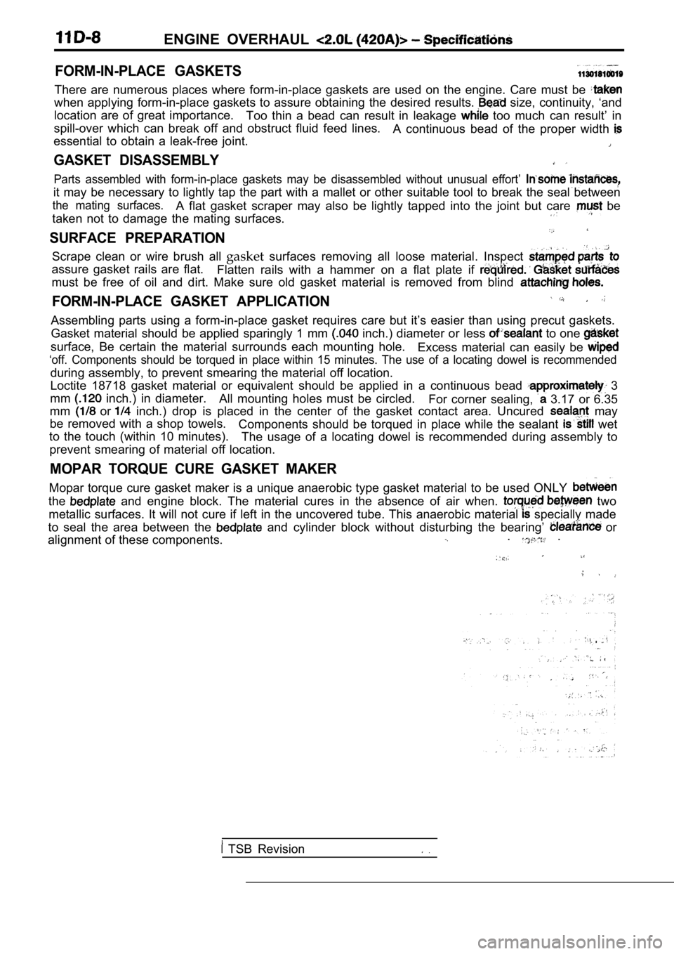
FORM-IN-PLACE GASKETS
There are numerous places where form-in-place gaskets are used on the engine. Care must be
when applying form-in-place gaskets to assure obtaining the desired results. size, continuity, ‘and
location are of great importance. Too thin a bead can result in leakage
too much can result’ in
spill-over which can break off and obstruct fluid f eed lines.
A continuous bead of the proper width
essential to obtain a leak-free joint.
GASKET DISASSEMBLY
Parts assembled with form-in-place gaskets may be d isassembled without unusual effort’
it may be necessary to lightly tap the part with a mallet or other suitable tool to break the seal between
the mating surfaces.A flat gasket scraper may also be lightly tapped in to the joint but care be
taken not to damage the mating surfaces.
SURFACE PREPARATION
Scrape clean or wire brush all gasketsurfaces removing all loose material. Inspect
assure gasket rails are flat.
Flatten rails with a hammer on a flat plate if
must be free of oil and dirt. Make sure old gasket material is removed from blind
FORM-IN-PLACE GASKET APPLICATION
Assembling parts using a form-in-place gasket requires care but it’s easier than using precut gaskets.
Gasket material should be applied sparingly 1 mm
inch.) diameter or less to one
surface, Be certain the material surrounds each mou nting hole.
Excess material can easily be
‘off. Components should be torqued in place within 15 minutes. The use of a locating dowel is recommen ded
during assembly, to prevent smearing the material off location.
Loctite 18718 gasket material or equivalent should be applied in a continuous bead
3
mm
inch.) in diameter. All mounting holes must be circled.
For corner sealing, 3.17 or 6.35
mm
or inch.) drop is placed in the center of the gasket contact area. Uncured may
be removed with a shop towels. Components should be torqued in place while the sea lant
wet
to the touch (within 10 minutes). The usage of a locating dowel is recommended during assembly to
prevent smearing of material off location.
MOPAR TORQUE CURE GASKET MAKER
Mopar torque cure gasket maker is a unique anaerobi c type gasket material to be used ONLY
the and engine block. The material cures in the absenc e of air when. two
metallic surfaces. It will not cure if left in the uncovered tube. This anaerobic material
specially made
to seal the area between the
and cylinder block without disturbing the bearing’ or
alignment of these components.. .
TSB Revision
Page 231 of 2103

ENGINE OVERHAUL Manifold
EGR tube
INTAKE MANIFOLD
(1) Remove intake air temperature sensor.
(2) Remove manifold absolute pressure (MAP) sensor mount-
ing screws.
(3) Remove manifold absolute pressure (MAP) sensor.
(4) Remove intake manifold stay.
(5) Remove EGR tube fasteners from the
and valve. Remove tube from engine.
Remove vacuum hose and electrical connection from in-
take manifold.
(7) Remove attaching
engine and remove intake
manifold from engine.
I .
TSB Revision
Page 263 of 2103
ENGINE OVERHAUL
NOTE
All upper bearing
in the crankcase have oil grooves.
All lower bearing shells installed in the (bedplate ) main
bearing caps are plain. Crankshaft end play is cont rolled
by a flanged bearing on the number three main beari ng
journal.
(6) Make certain oil holes in block line up with oi l hole in
bearings and bearing tabs seat in the
tab slots.
(7) Oil the bearings and, journals and install cran kshaft.
Caution
D o get oil on
If may effect the sealer ability the
to cylinder block.
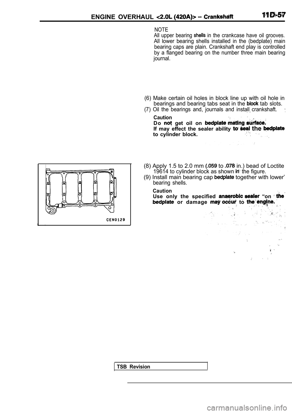
(8) Apply 1.5 to 2.0 mm to in.) bead of Loctite
19614 to cylinder block as shown the figure.
(9) Install main bearing cap together with lower’
bearing shells.
Caution
Use only the specified “on
or damage to
TSB Revision
Page 384 of 2103
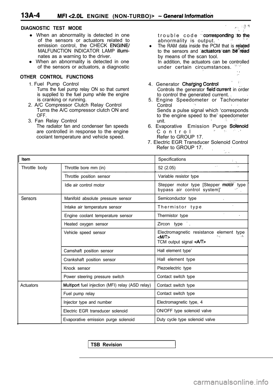
ENGINE (NON-TURBO)>
DIAGNOSTIC TEST MODE
l When an abnormality is detected in one
of the sensors or actuators related to
emission control, the CHECK
MALFUNCTION INDICATOR LAMP
nates as a warning to the driver.
l When an abnormality is detected in one
of the sensors or actuators, a diagnostic
OTHER CONTROL FUNCTIONS
t r o u b l e c o d e
a b n o r m a l i t y i s o u t p u t .
lThe RAM data inside the PCM that is
to the sensors and
by means of the scan tool.
In addition, the actuators can be controlled
under certain circumstances. . ,
1. Fuel Pump Control
Turns the fuel pump relay ON so that current
is supplied to the fuel pump while the engine
is cranking or running.
2. A/C Compressor Clutch Relay Control Turns the A/C compressor clutch ON and
OFF.
3. Fan Relay Control
The radiator fan and condenser fan speeds
are controlled in response to the engine
coolant temperature and vehicle speed. 4. Generator
Controls the generator in order
to control the generated current.
5. Engine Speedometer or Tachometer
Control.
Sends a pulse signal which ‘corresponds
to the engine speed to the’ speedometer
unit..
6. Evaporative Emission Purge
C o n t r o l
Refer to GROUP 17.
7. Electric EGR Transducer Solenoid Control Refer to GROUP 17.
Throttle body
Sensors
Actuators
Specifications
Throttle bore mm (in) 52 (2.05)
Throttle position sensor Variable resistor type
Idle air control motor
Stepper motor type [Stepper type
bypass air control system]’,
Manifold absolute pressure sensor Semiconductor type
Intake air temperature sensorT h e r m i s t o r t y p e
Engine coolant temperature sensorThermistor type .
Heated oxygen sensorZircon type .
Vehicle speed sensorElectromagnetic resistance element type
TCM output signal
Camshaft position sensor Hall element type’
Crankshaft position sensor
Hall element type
Knock sensor Piezoelectric type
Power steering pressure switch Contact switch type
fuel injection (MFI) relay (ASD relay)
Contact switch type
Fuel pump relay Contact switch type
Injector type and number Electromagnetic type, 4
Electric EGR transducer solenoid ON/OFF type solenoid valve
Evaporative emission purge solenoid Duty cycle type solenoid valve
TSB Revision
Page 385 of 2103
ENGINE (NON-TURBO)>
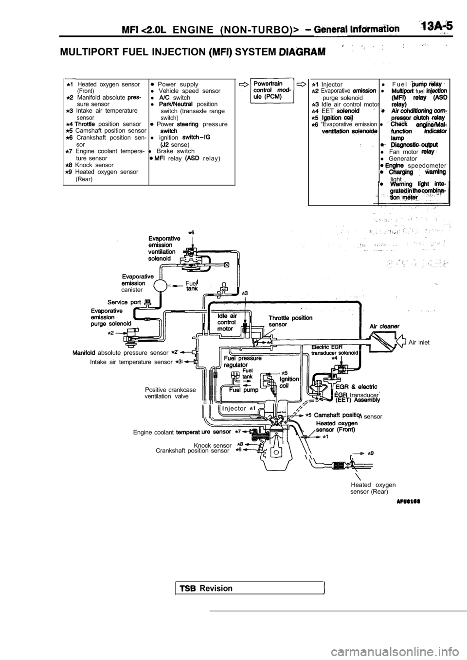
MULTIPORT FUEL INJECTION SYSTEM
Heated oxygen sensor Power supply(Front)l Vehicle speed sensor
Manifold absolute l switch
sure sensor l position Intake air temperature
switch (transaxle rangesensor switch) position sensor Power pressure Camshaft position sensor Crankshaft position sen- l ignitionsor sense) Engine coolant tempera- l Brake switch
ture sensor relay r e l a y ) Knock sensor Heated oxygen sensor(Rear)
Injector l
F u e l Evaporative l fuel purge solenoid Idle air control motor EET
“Evaporative emission l
.l Fan motor l Generator speedometer
light
.
Fuel
canister
absolute pressure sensor
Intake air temperature sensor
Positive crankcase
ventilation valve
I n j e c t o r
transducer
sensor
Engine coolant
Knock sensor
Crankshaft position sensor
Air inlet
Heated oxygen
sensor (Rear)
Revision