1990 MITSUBISHI SPYDER air bleeding
[x] Cancel search: air bleedingPage 74 of 2103
ENGINE On-vehicle Service
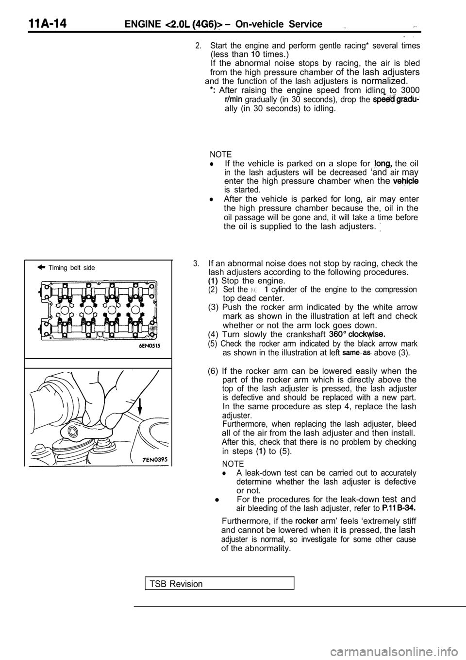
Timing belt side
.
2.Start the engine and perform gentle racing* several times
(less than times.)
If the abnormal noise stops by racing, the air is b led
from the high pressure chamber of the lash adjusters
and the function of the lash adjusters is normalized.
After raising the engine speed from idling to 3000
gradually (in 30 seconds), drop the
ally (in 30 seconds) to idling.
NOTE
lIf the vehicle is parked on a slope for the oil
in the lash adjusters will be decreased ‘andairmay
enter the high pressure chamber when the
is started.
lAfter the vehicle is parked for long, air may enter
the high pressure chamber because the, oil in the
oil passage will be gone and, it will take a time b efore
the oil is supplied to the lash adjusters.
3.If an abnormal noise does not stop by racing, check the
lash adjusters according to the following procedure s.
Stop the engine.
(2)Set the NG. cylinder of the engine to the compression
top dead center.
(3) Push the rocker arm indicated by the white arro w
mark as shown in the illustration at left and check
whether or not the arm lock goes down.
(4) Turn slowly the crankshaft
(5) Check the rocker arm indicated by the black arr ow mark
as shown in the illustration at left above (3).
(6) If the rocker arm can be lowered easily when th e
part of the rocker arm which is directly above the
top of the lash adjuster is pressed, the lash adjus ter
is defective and should be replaced with a new part .
In the same procedure as step 4, replace the lash
adjuster.
Furthermore, when replacing the lash adjuster, bleed
all of the air from the lash adjuster and then install.
After this, check that there is no problem by check ing
in steps to (5).
NOTE
lA leak-down test can be carried out to accurately
determine whether the lash adjuster is defective
or not.
l For the procedures for the leak-down test and
air bleeding of the lash adjuster, refer to
Furthermore, if the arm’ feels ‘extremely stiff
and cannot be lowered when it is pressed, the lash
adjuster is normal, so investigate for some other c ause
of the abnormality.
TSB Revision
Page 138 of 2103
11 ENGINE OVERHAUL Rocker
.
INSPECTION
CAMSHAFT
(1) Measure the cam height.
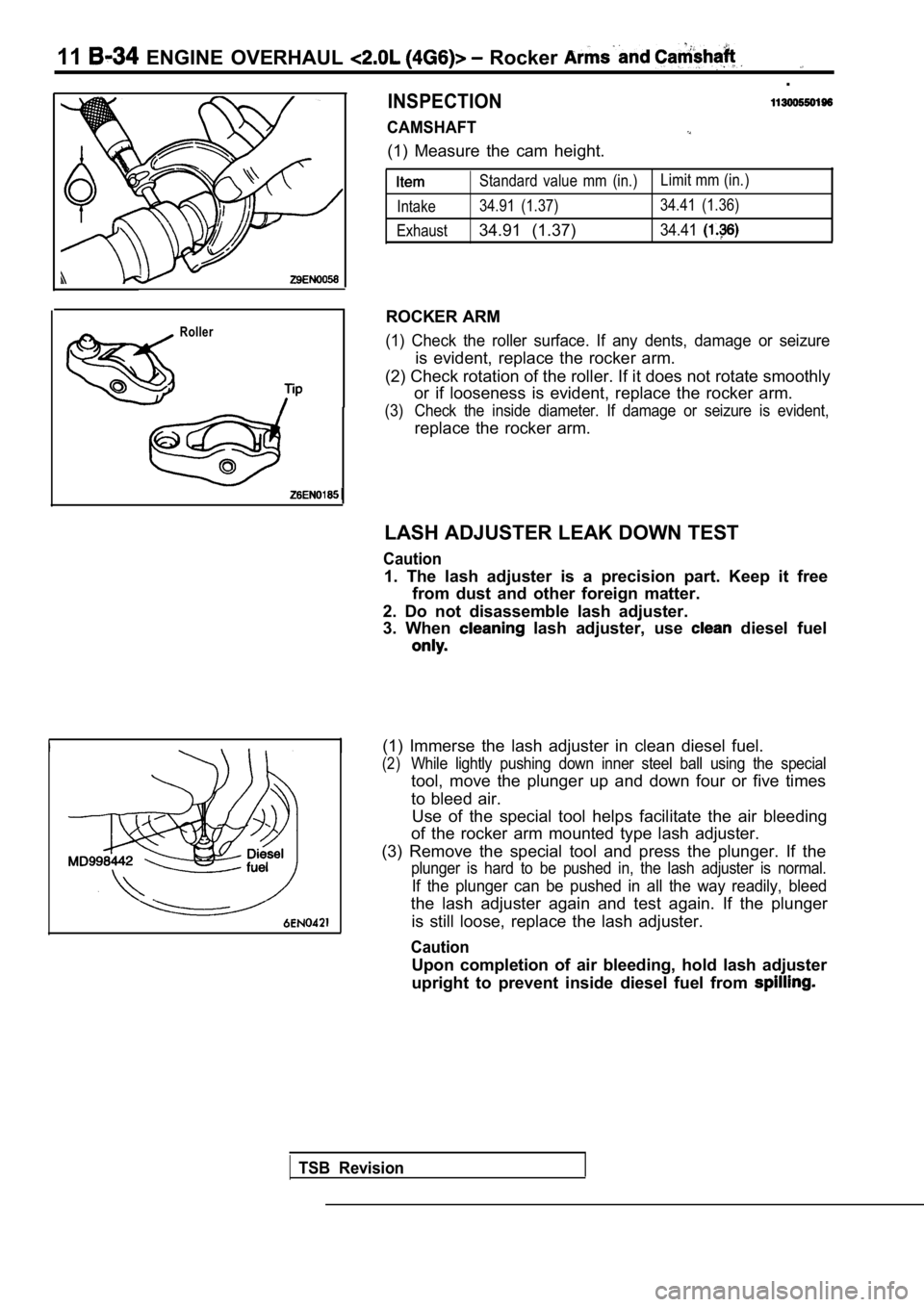
Roller
Standard value mm (in.)Limit mm (in.)
Intake 34.91 (1.37) 34.41 (1.36)
Exhaust
34.91 (1.37)34.41
ROCKER ARM
(1) Check the roller surface. If any dents, damage or seizure
is evident, replace the rocker arm.
(2) Check rotation of the roller. If it does not ro tate smoothly
or if looseness is evident, replace the rocker arm.
(3) Check the inside diameter. If damage or seizure is evident,
replace the rocker arm.
LASH ADJUSTER LEAK DOWN TEST
Caution
1. The lash adjuster is a precision part. Keep it f ree
from dust and other foreign matter.
2. Do not disassemble lash adjuster.
3. When
lash adjuster, use diesel fuel
(1) Immerse the lash adjuster in clean diesel fuel.
(2)While lightly pushing down inner steel ball using t he special
tool, move the plunger up and down four or five tim es
to bleed air. Use of the special tool helps facilitate the air bl eeding
of the rocker arm mounted type lash adjuster.
(3) Remove the special tool and press the plunger. If the
plunger is hard to be pushed in, the lash adjuster is normal.
If the plunger can be pushed in all the way readily, bleed
the lash adjuster again and test again. If the plun ger
is still loose, replace the lash adjuster.
Caution
Upon completion of air bleeding, hold lash adjuster
upright to prevent inside diesel fuel from
TSB Revision
Page 139 of 2103
ENGINE OVERHAUL Rocker Arms and
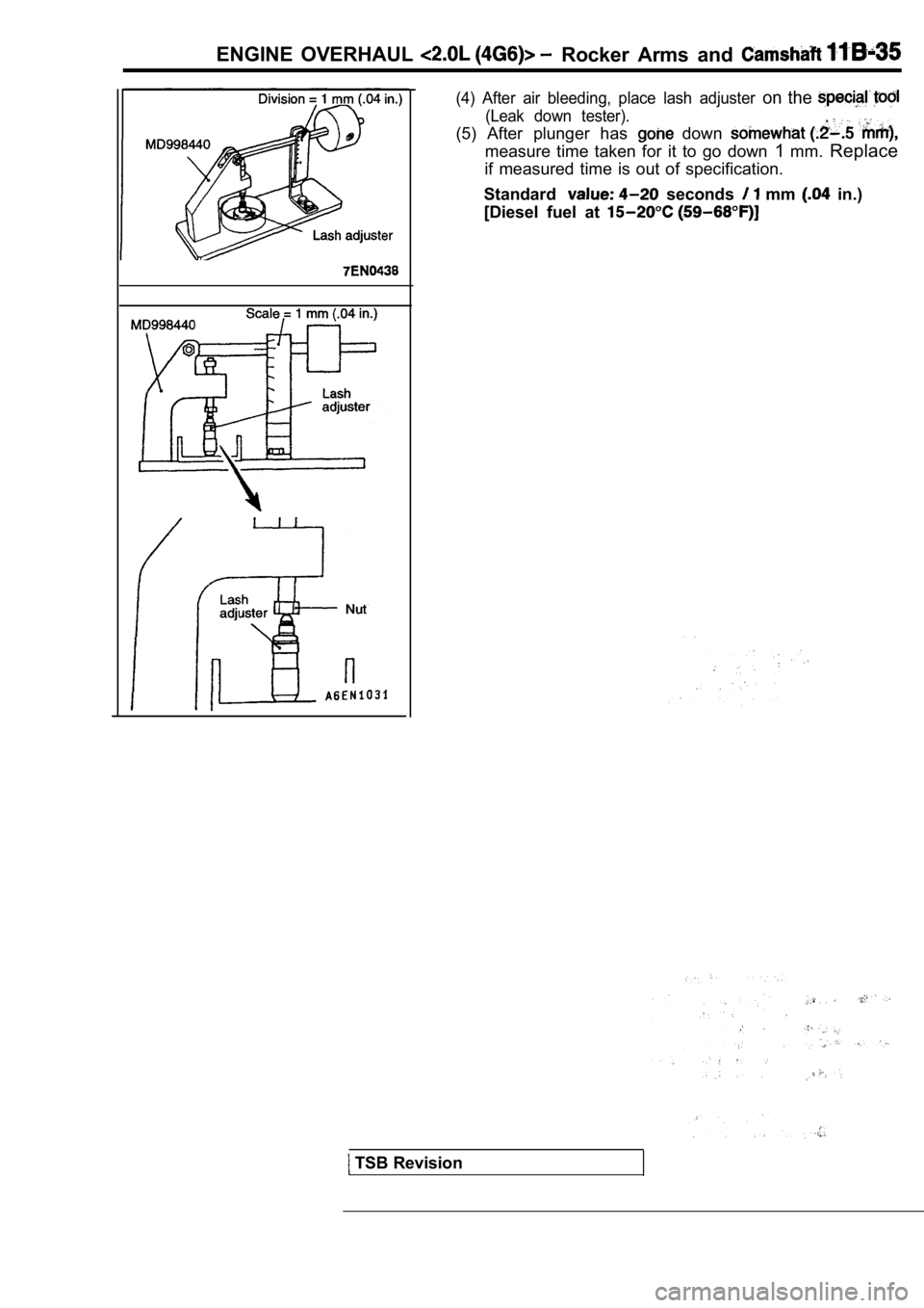
(4) After air bleeding, place lash adjuster on the
(Leak down tester).
(5) After plunger has down
measure time taken for it to go down 1mm. Replace
if measured time is out of specification.
Standard
seconds mm in.)
[Diesel fuel at
TSB Revision
Page 282 of 2103

ENGINE On-vehicle
NOTE
lIf the vehicle is parked on a slope for long, oil
in the lash adjusters will
and ‘air may
enter the high-pressure’ chamber when the vehicle
i s s t a r t e d .
lAfter the vehicle is parked for long, air may enter the high-pressure
because, the oil in the
oil passage will be gone it take a time before
the oil is supplied to the
3.If an abnormal noise does not stop by racing, check the
lash adjusters according to the following procedure s.
Stop the enaine.
of the engine to the compression
top dead center.
(3) Push the rocker arm indicated by the white arrow
mark as shown in the illustration at left and check
whether or not the arm lock goes down.
(4) Turn slowly the crankshaft
clockwise.
(5) Check the rocker arm indicated by the black arr ow
mark as shown in the illustration at left same as above
(3).(6) If the rocker arm can be lowered easily when th e
part of the rocker arm which is directly above the
top of the lash adjuster is pressed, the lash adjus ter
is defective and should be replaced with a new part .
Furthermore, when replacing the lash adjuster, blee d
all of the air from the lash adjuster and then install.
After this, check that there is no problem by check ing
in steps to (5).
NOTE
lA leak-down test can be carried out to accurately
determine whether the lash adjuster is defective
or not.
lFor the procedures for the leak-down test and
air bleeding of the lash adjuster, refer to 11
Furthermore, if the arm feels extremely stiff
and cannot be lowered when it is
the lash
adjuster is normal, so some other cause
of the abnormality.
TSBRevision
Page 342 of 2103
ENGINE OVERHAUL Rocker Arms Camshaft
I
INSPECTION
CAMSHAFT.
(1) Measure the cam height. Standard
Intake 37.39 mm (1.4720
Exhaust 37.47 mm (1.4752
Limit:
Intake 36.69 mm (1.4524 in.)
Exhaust 36.97 mm (1.4655 in.)
NOTE
The camshaft identification mark is stamped on the
opposite end of the camshaft sprocket side.
ROCKER ARM
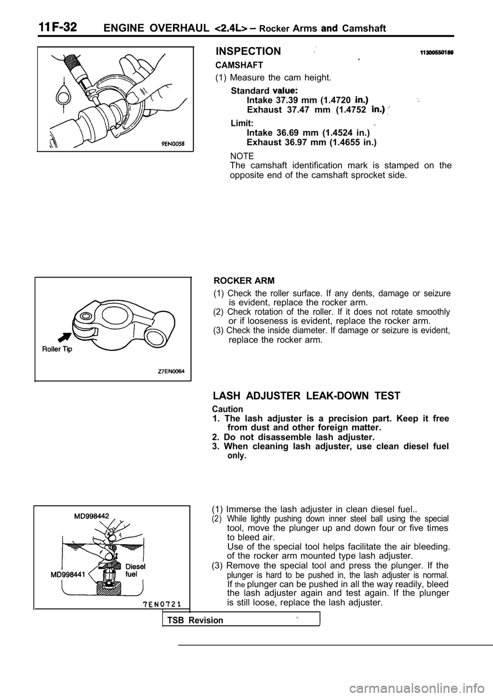
(1) Check the roller surface. If any dents, damage or seizure
is evident, replace the rocker arm.
(2) Check rotation of the roller. If it does not rotate smoothly
or if looseness is evident, replace the rocker arm.
(3) Check the inside diameter. If damage or seizure is evident,
replace the rocker arm.
LASH ADJUSTER LEAK-DOWN TEST
Caution
1. The lash adjuster is a precision part. Keep it f ree
from dust and other foreign matter.
2. Do not disassemble lash adjuster.
3. When cleaning lash adjuster, use clean diesel fu el
only.
Use of the special tool helps facilitate the air bleeding.
of the rocker arm mounted type lash adjuster.
(3) Remove the special tool and press the plunger. If the
plunger is hard to be pushed in, the lash adjuster is normal.
Ifthe plunger can be pushed in all the way readily, bleed
the lash adjuster again and test again. If the plun ger
is still loose, replace the lash adjuster.
TSB Revision
(1) Immerse the lash adjuster in clean diesel fuel. .
(2)While lightly pushing down inner steel ball using t he special
tool, move the plunger up and down four or five tim es
to bleed air.
Page 343 of 2103
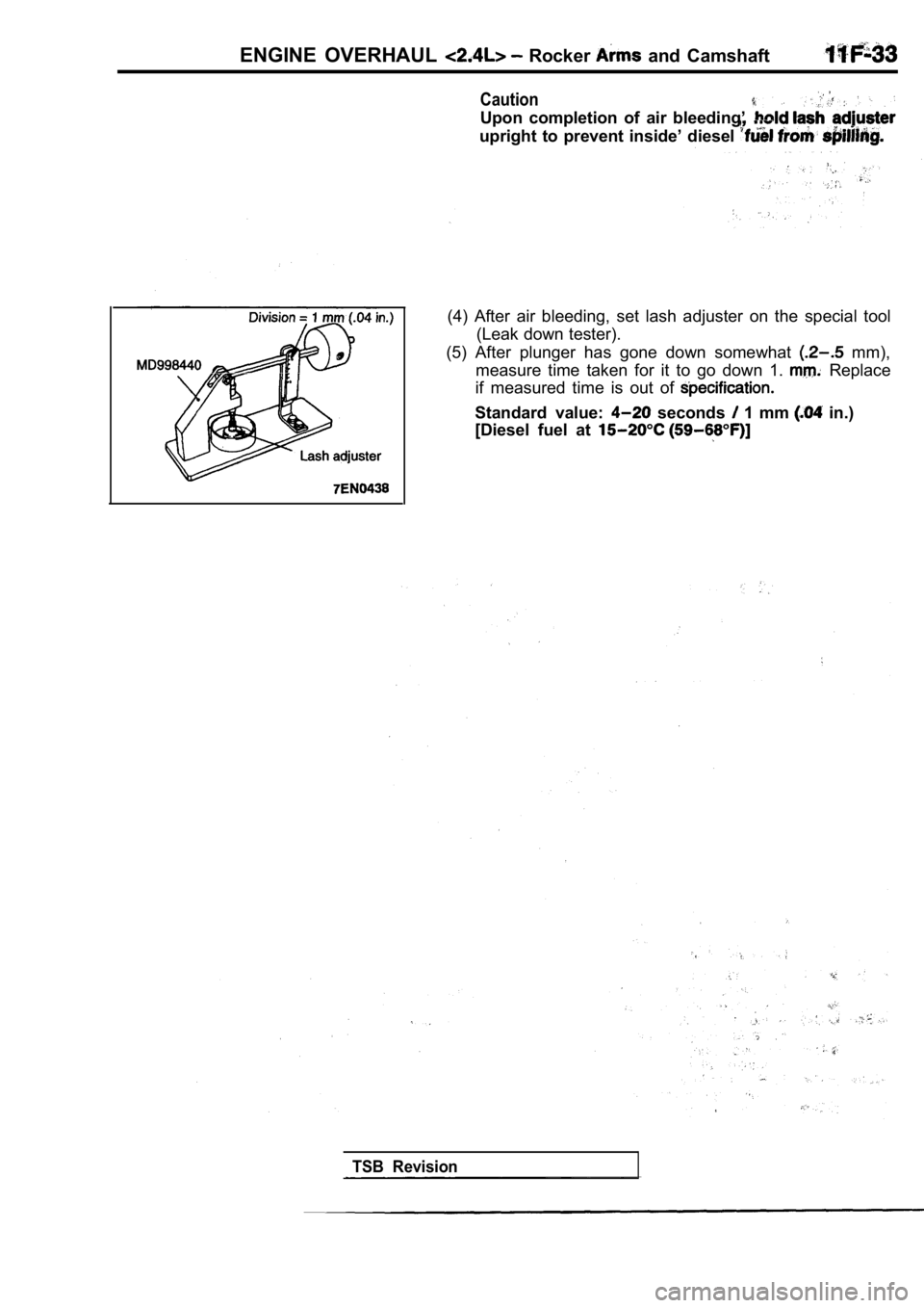
ENGINE OVERHAUL Rocker and Camshaft
Caution
Upon completion of air bleeding’
upright to prevent inside’ diesel
(4) After air bleeding, set lash adjuster on the special tool
(Leak down tester).
(5) After plunger has gone down somewhat
mm),
measure time taken for it to go down 1.
Replace
if measured time is out of
Standard value: seconds 1 mm in.)
[Diesel fuel at
TSB Revision
Page 1651 of 2103
BASIC BRAKE SYSTEM
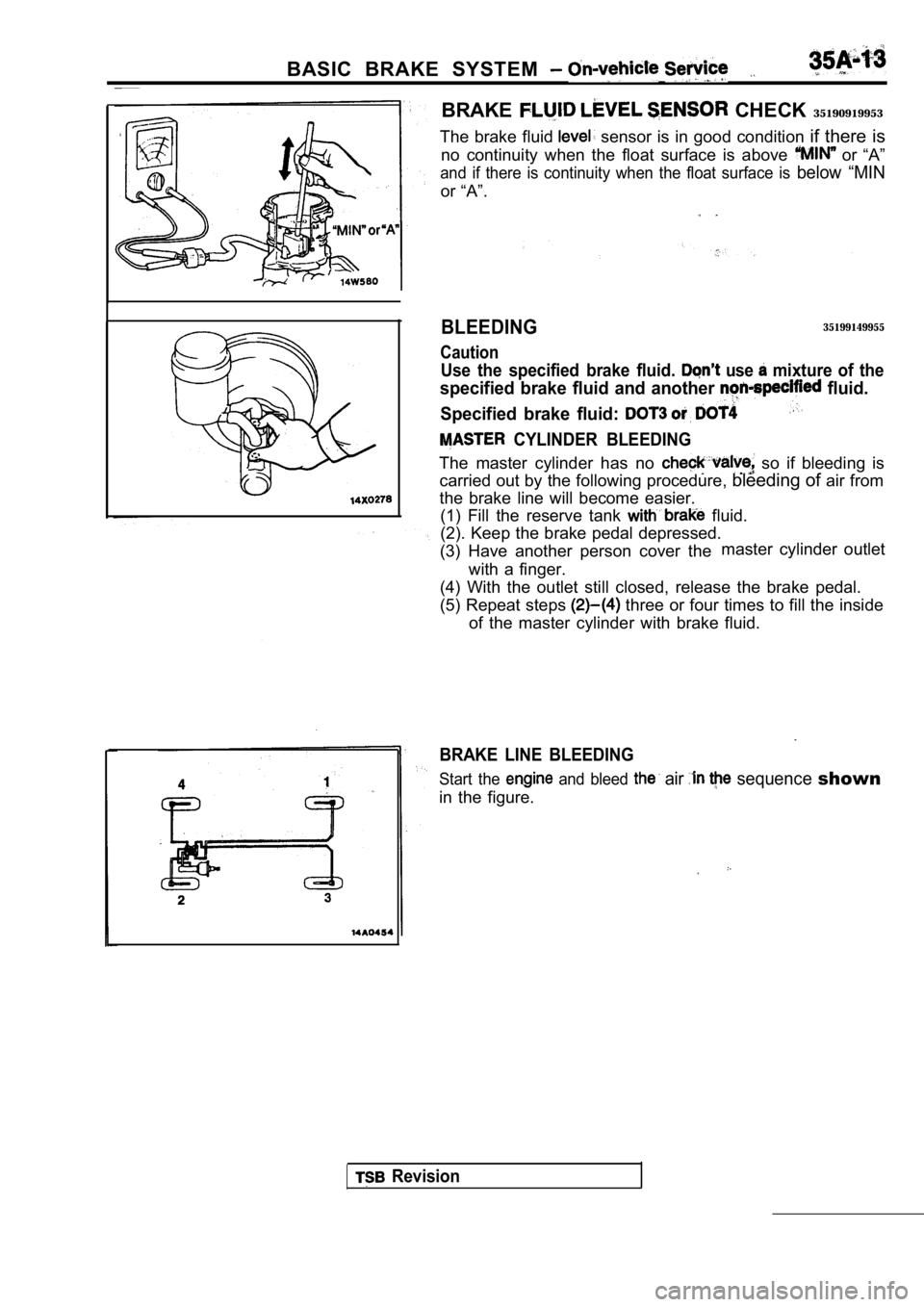
BRAKE CHECK 35190919953
The brake fluid
sensor is in good condition if there is
no continuity when the float surface is above
or “A”
and if there is continuity when the float surface i s below “MIN
or “A”.
BLEEDING
Caution
35199149955
Use the specified brake fluid. use mixture of the
specified brake fluid and another fluid.
Specified brake fluid:
CYLINDER BLEEDING
The master cylinder has no so if bleeding is
carried out by the following procedure, bleeding of air from
the brake line will become easier. (1) Fill the reserve tank
fluid.
(2). Keep the brake pedal depressed.
(3) Have another person cover the master cylinder outlet
with a finger.
(4) With the outlet still closed, release the brake pedal.
(5) Repeat steps
three or four times to fill the inside
of the master cylinder with brake fluid.
BRAKE LINE BLEEDING
Start the and bleed air sequence shown
in the figure.
Revision
Page 1663 of 2103
BASIC BRAKE SYSTEM Master Cylinder and Brake Booster
MASTER CYLINDER AND BRAKEBOOSTER
REMOVAL AND INSTALLATION
Pre-removal Operationl
Brake Fluid Draining
l Clutch Fluid Reservoir Bracket
(Refer to GROUP Clutch Control.)
l Battery Removal Engine (Non-turbo)>
l Relay Assembly Mounting Bolts Removal
Engine (Non-turbo)>
lWasher Tank Bolts Removal (Non-turbo)>lCentermember Assemblv Bolts Removal Engine (Turbo) arid Engine> (Refer toGROUP 32 Engine Roll Stopper, Centermember.)l Engine Mount Bracket Removal Engine
(Turbo) and Engine> (Refer to GROUP 32 Engine Mounting.)l Air Conditioning Compressor Mounting Bolts
Removal Engine (Turbo) and Engine>
(Refer to GROUP 55 Compressor and TensionPulley.)l Air Conditioning High Pressure Hose ClampMounting Bolts Engine (Turbo) and Engine>
l Power Steering Pressure Hose, Pipe and Return
Pipe Clamp Mounting Bolts Removal Engine and
I GROUP Power Steering Hoses.)
Flared brake line nuts
15 Nm11
Post-installation OperationlPower Steering Pressure Hose, Pipe and Pipe Clamp Mounting Bolts Installation Engine(Turbo) and Engine>
(Refer to GROUP Power Hoses.]
l Air Conditioning High Pressure Hose Clamp
Mounting Bolts
Engine and Engine>
l A i r C o n d i t i o n i n g C o m p r e s s o r
Installation Engine (Turbo) and ngines
(Refer to GROUP 55 Compressor and TensionPulley.)l Engine Mount Bracket Installation Engine(Turbo) and Engine> (Refer to GROUP 32 Engine Mounting.)lCentermember Assembly Mounting Bolts Installation Engine (Turbo) and Engine> (Refer toGROUP 32 Engine Roll Stopper Centermember.)l Washer Tank Mounting Installation Engine (Non-turbo)>l
Relay Assembly Mounting Bolts Installation Engine (Non-turbo)>l Battery Engine (Non-turbo)>
l Clutch Fluid Reservoir Bracket
(Refer to GROUP Clutch Control.)
l Brake Fluid Supplying
l Brake Line Bleeding (Refer to
l
Brake Pedal Adjustment (Refer to
I
10 Nm714 Nin10
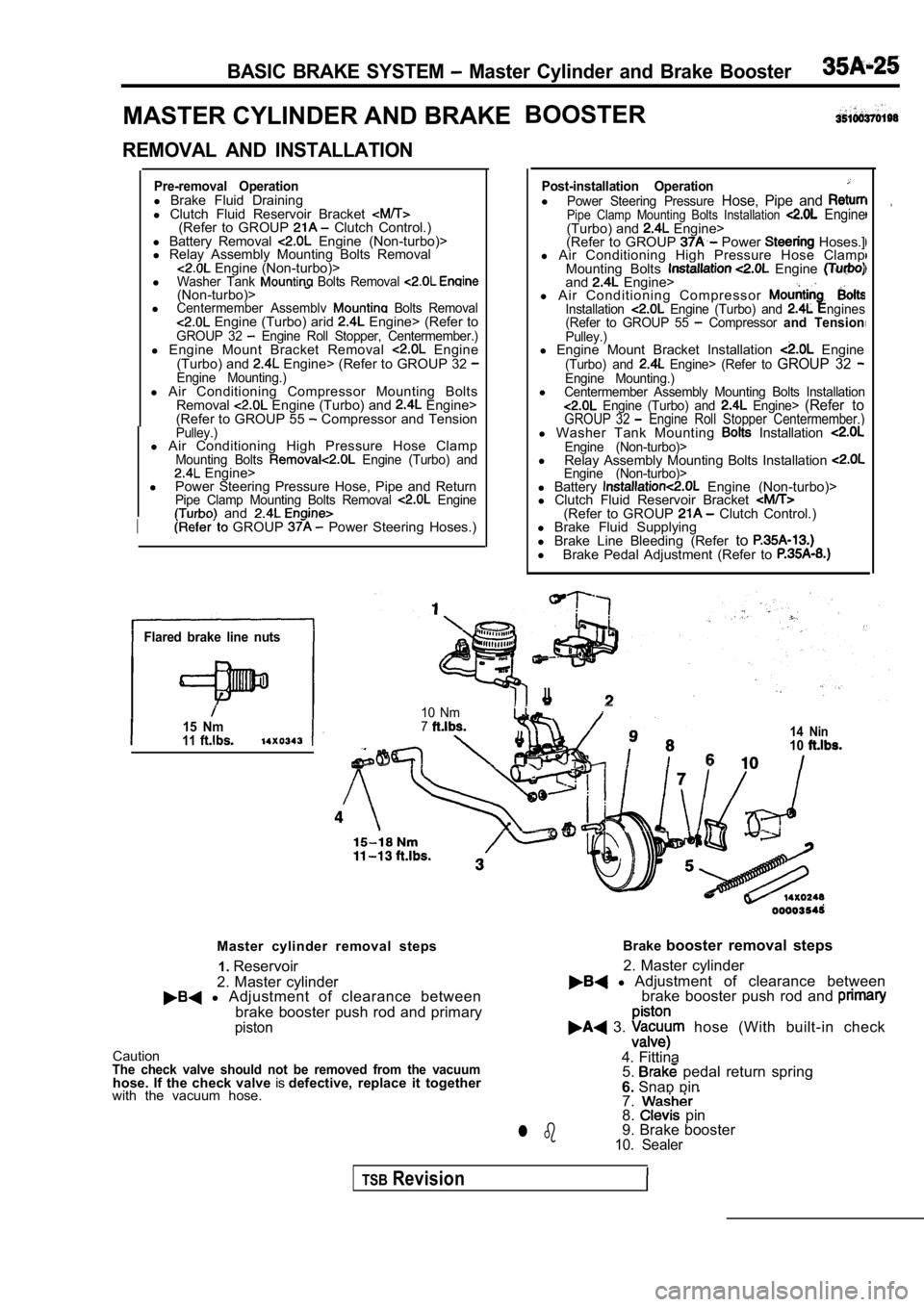
Master cylinder removal steps
2. Master cylinder1.
Reservoir
l Adjustment of clearance between
brake booster push rod and primary
piston
CautionThe check valve should not be removed from the vacu umhose. If the check valve isdefective, replace it together
with the vacuum hose. Brake
booster removal steps
l Adjustment of clearance between
2. Master cylinder
brake booster push rod and
3. hose (With built-in check
4. Fittina 5.
pedal return spring
6. Snap pin
7.
8. pin
9. Brake booster
10. Sealerl b
TSBRevision