1990 MITSUBISHI SPYDER height adjustment
[x] Cancel search: height adjustmentPage 835 of 2103
CLUTCH -On-vehicle Service
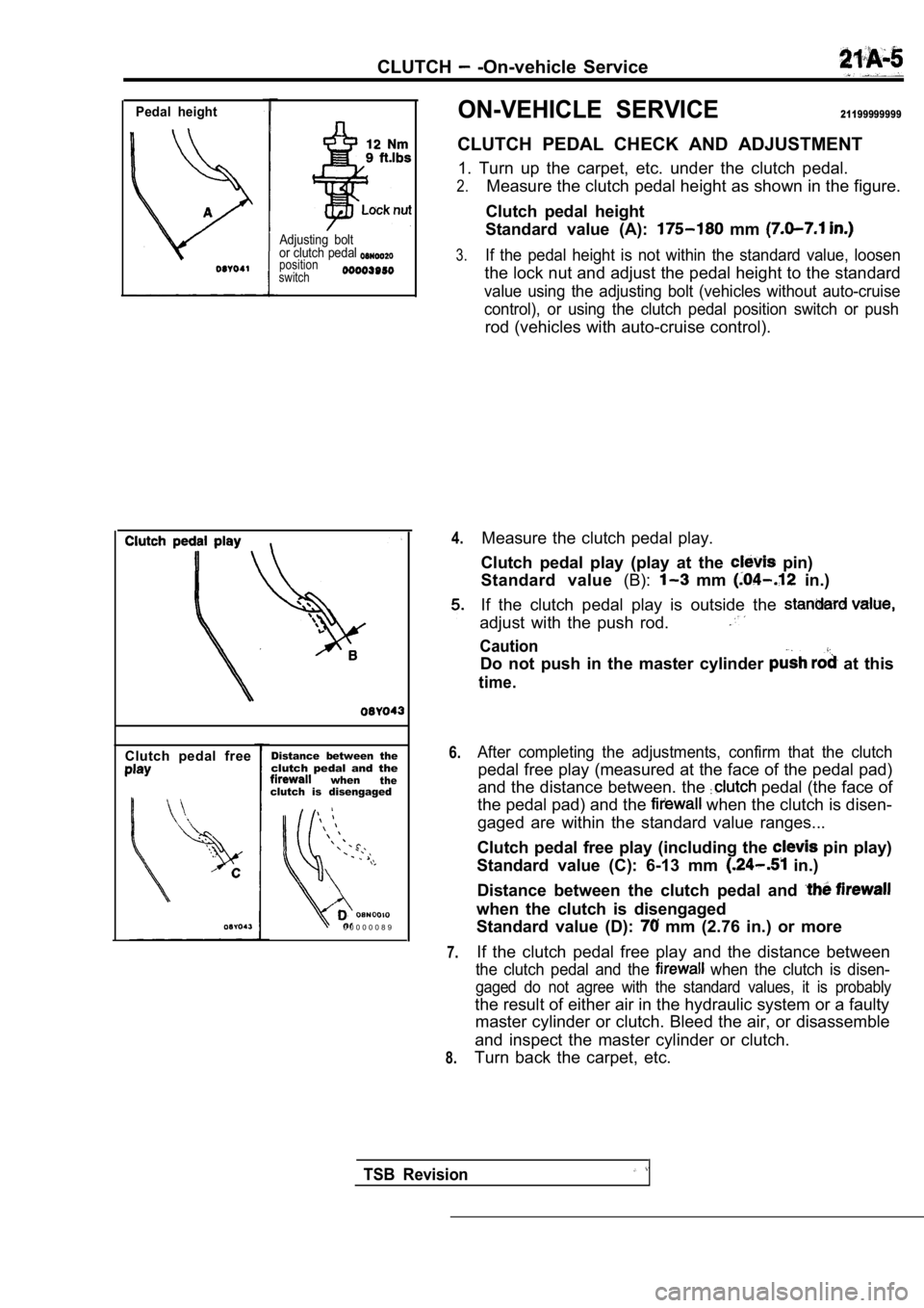
Pedal height
Adjusting bolt
or clutch pedal
position
switch
Clutch pedal freeDistance between theclutch pedal and thewhentheclutch is disengaged
0 0 0 0 0 0 8 9
ON-VEHICLE SERVICE21199999999
CLUTCH PEDAL CHECK AND ADJUSTMENT
1. Turn up the carpet, etc. under the clutch pedal.
2.Measure the clutch pedal height as shown in the fig ure.
Clutch pedal height
Standard value (A):
mm
3.If the pedal height is not within the standard valu e, loosen
the lock nut and adjust the pedal height to the sta ndard
value using the adjusting bolt (vehicles without au to-cruise
control), or using the clutch pedal position switch or push
rod (vehicles with auto-cruise control).
4.
6.
7.
8.
Measure the clutch pedal play.
Clutch pedal play (play at the
pin)
Standard value (B):
mm in.)
If the clutch pedal play is outside the
adjust with the push rod.
Caution
Do not push in the master cylinder at this
time.
After completing the adjustments, confirm that the clutch
pedal free play (measured at the face of the pedal pad)
and the distance between. the
pedal (the face of
the pedal pad) and the
when the clutch is disen-
gaged are within the standard value ranges...
Clutch pedal free play (including the
pin play)
Standard value (C): 6-13 mm
in.)
Distance between the clutch pedal and
when the clutch is disengaged
Standard value (D):
mm (2.76 in.) or more
If the clutch pedal free play and the distance betw een
the clutch pedal and the when the clutch is disen-
gaged do not agree with the standard values, it is probably
the result of either air in the hydraulic system or a faulty
master cylinder or clutch. Bleed the air, or disass emble
and inspect the master cylinder or clutch.
Turn back the carpet, etc.
TSB Revision
Page 962 of 2103
MANUAL TRANSAXLE OVERHAUL Transfer
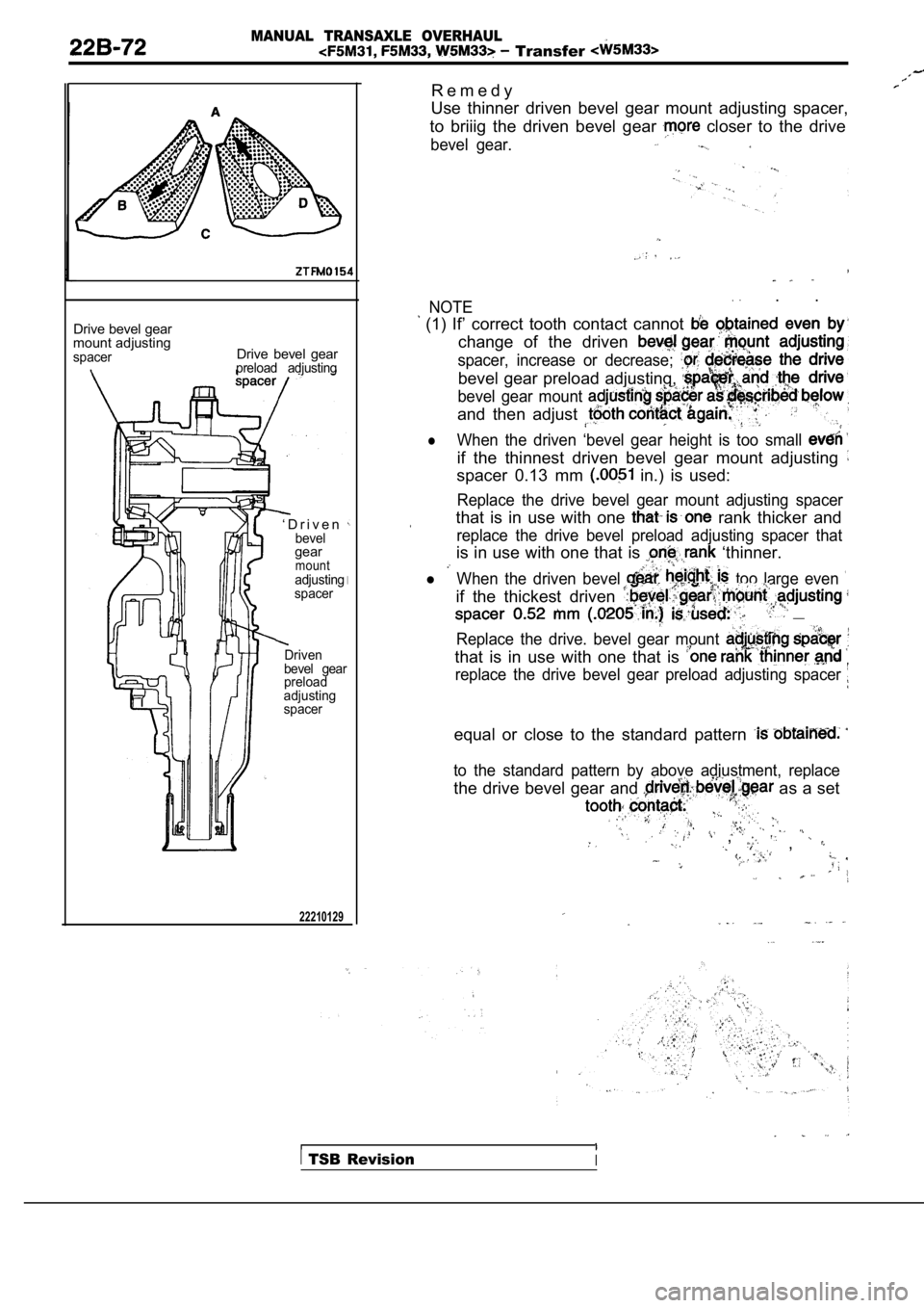
Drive bevel gear
mount adjusting
spacerDrive bevel gearpreload adjusting
‘ D r i v e nbevelgearmountadjusting
spacer
Driven
bevel gear
preload
adjusting
spacer
22210129
R e m e d y
Use thinner driven bevel gear mount adjusting space r,
to briiig the driven bevel gear
closer to the drive
bevel gear.
NOTE . .
(1) If’ correct tooth contact cannot change of the driven
spacer, increase or decrease;
bevel gear preload adjusting,
bevel gear mount
and then adjust
lWhen the driven ‘bevel gear height is too small
if the thinnest driven bevel gear mount adjusting
spacer 0.13 mm in.) is used:
Replace the drive bevel gear mount adjusting spacer
that is in use with one rank thicker and
replace the drive bevel preload adjusting spacer th at
is in use with one that is ‘thinner.
l When the driven bevel too large even
if the thickest driven __
Replace the drive. bevel gear mount
that is in use with one that is
replace the drive bevel gear preload adjusting spacer
equal or close to the standard pattern
to the standard pattern by above adjustment, replac e
the drive bevel gear and as a set
, ,
TSB RevisionI
Page 1212 of 2103
AUTOMATIC TRANSAXLE
OVERHAUL Specifications
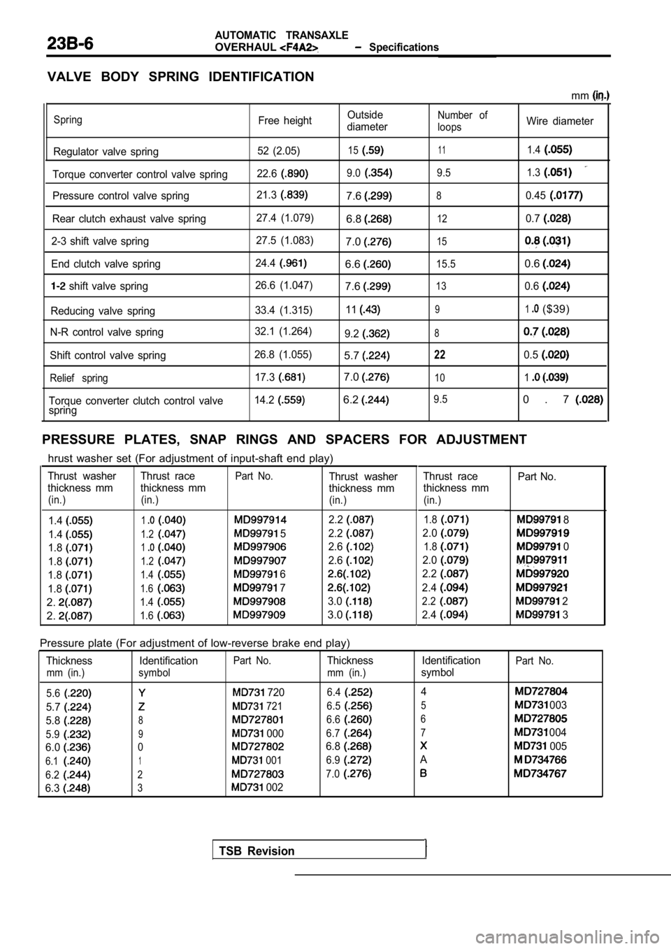
VALVE BODY SPRING IDENTIFICATION
mm
Spring
Regulator valve spring
Torque converter control valve spring
Pressure control valve spring
Rear clutch exhaust valve spring
2-3 shift valve spring
End clutch valve spring
shift valve spring
Reducing valve spring
N-R control valve spring
Shift control valve spring
Relief spring
Torque converter clutch control valve
spring Free height
52 (2.05)
22.6
21.3
27.4 (1.079)
27.5 (1.083)
24.4
26.6 (1.047)
33.4 (1.315)
32.1 (1.264)
26.8 (1.055) 17.3
14.2
Outside
diameter
15
9.0
7.6
6.8
7.0
6.6
7.6
11
9.2
5.7
7.0
6.2
Number of
loops
11
9.5
8
12
15
15.5
13
9
8
22
10
9.5
Wire diameter
1.4
1.3
0.45
0.7
0.6
0.6
1($39)
0.5
1
0 . 7
PRESSURE PLATES, SNAP RINGS AND SPACERS FOR ADJUSTM ENT
TSB Revision
hrust washer set (For adjustment of input-shaft end play)
Thrust washer Thrust racePart No.Thrust washer
thickness mm thickness mm thickness mm
(in.) (in.) (in.)
1.412.2
1.41.2 52.2
1.812.6
1.81.22.6
1.81.4 6
1.81.6 7
2.1.43.0
2.1.63.0
Thrust race
thickness mm
(in.)
Part No.
1.8 8
2.0
1.8 0
2.0
2.2
2.4
2.2 2
2.4
3
Pressure plate (For adjustment of low-reverse brake end play)
Thickness IdentificationPart No.Thickness
mm (in.) symbol mm (in.)
5.6
7206.4
5.7 721 6.5
5.886.6
5.99 0006.7
6.006.8
6.11 0016.9
6.227.0
6.33 002 Identification
symbol
4
5
6 7
A
Part No.
003
004
005
Page 1395 of 2103
AUTOMATIC TRANSAXLE
Transfer
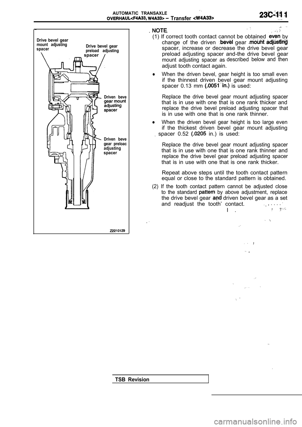
Drive bevel gearmount adjusting
spacer
.
Drive bevel gearpreload adjusting spacer
Driven beve
Driven beve
gear preloac
adjustingspacer
.
(1) If correct tooth contact cannot be obtained by
change of the driven
gear
spacer, increase or decrease the drive bevel gear preload adjusting spacer and-the drive bevel gear
mount adjusting spacer as described
below and then
adjust tooth contact again.
lWhen the driven bevel, gear height is too small eve
n
if the thinnest driven bevel gear mount adjusting
spacer 0.13 mm
is used:
Replace the drive bevel gear mount adjusting spacer
that is in use with one that is one rank thicker an d
replace the drive bevel preload adjusting spacer th at
is in use with one that is one rank thinner.
lWhen the driven bevel gear height is too large even
if the thickest driven bevel gear mount adjusting
spacer 0.52 in.) is used:
Replace the drive bevel gear mount adjusting spacer
that is in use with one that is one rank thinner and
replace the drive bevel gear preload adjusting spac er
that is in use with one that is one rank thicker.
Repeat above steps until the tooth contact pattern
equal or close to the standard pattern is obtained.
(2) If the tooth contact pattern cannot be adjusted close
to the standard
by above adjustment, replace
the drive bevel gear driven bevel gear as a set
and readjust the tooth’ contact.
, . . . .
I .
.
TSB Revision
Page 1567 of 2103
REAR AXLE Differential
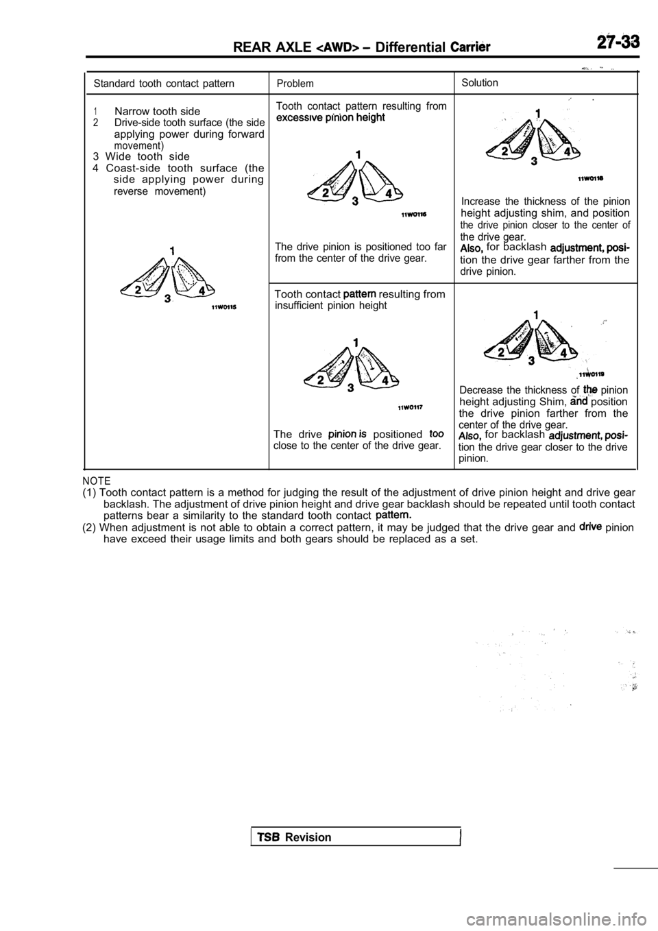
Standard tooth contact patternProblemSolution
.
1Narrow tooth sideTooth contact pattern resulting from. .
2Drive-side tooth surface (the side
applying power during forward
movement)3 Wide tooth side
4 Coast-side tooth surface (the side applying power during
reverse movement)Increase the thickness of the pinion
height adjusting shim, and position
the drive pinion closer to the center of
4
The drive pinion is positioned too far the drive gear.
from the center of the drive gear. for backlash
tion the drive gear farther from the
drive pinion.
Tooth contact resulting from
insufficient pinion height
Decrease the thickness of pinion
height adjusting Shim, position
the drive pinion farther from the
The drive
positioned center of the drive gear.
close to the center of the drive gear. for backlash
tion the drive gear closer to the drive pinion.
NOTE
(1) Tooth contact pattern is a method for judging t he result of the adjustment of drive pinion height and drive gear
backlash. The adjustment of drive pinion height and drive gear backlash should be repeated until tooth contact
patterns bear a similarity to the standard tooth co ntact
(2) When adjustment is not able to obtain a correct pattern, it may be judged that the drive gear and pinion
have exceed their usage limits and both gears shoul d be replaced as a set.
Revision
Page 1568 of 2103
27-34REAR AXLE. Differential
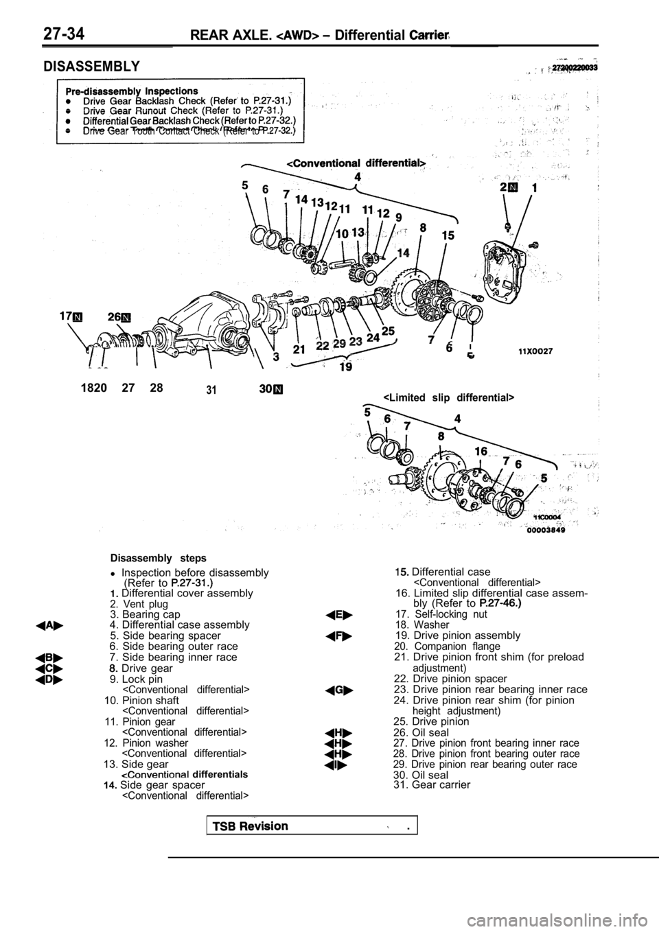
DISASSEMBLY
Drive Gear Tooth Contact Check (Refer to
1820 27 2831
Disassembly steps
l Inspection before disassembly
(Refer to
Differential cover assembly2. Vent plug3. Bearing cap
4. Differential case assembly
5. Side bearing spacer
6. Side bearing outer race
7. Side bearing inner race
Drive gear
9. Lock pin
11. Pinion gear
12. Pinion washer
13. Side gear differentials
14. Side gear spacer
Differential case
bly (Refer to
17. Self-locking nut
18. Washer
19. Drive pinion assembly20. Companion flange21. Drive pinion front shim (for preload
adjustment)22. Drive pinion spacer
23. Drive pinion rear bearing inner race
24. Drive pinion rear shim (for pinion
height adjustment)25. Drive pinion
26. Oil seal
27. Drive pinion front bearing inner race
28. Drive pinion front bearing outer race
29. Drive pinion rear bearing outer race
30. Oil seal 31. Gear carrier
.
Page 1571 of 2103
AXLE Differential’
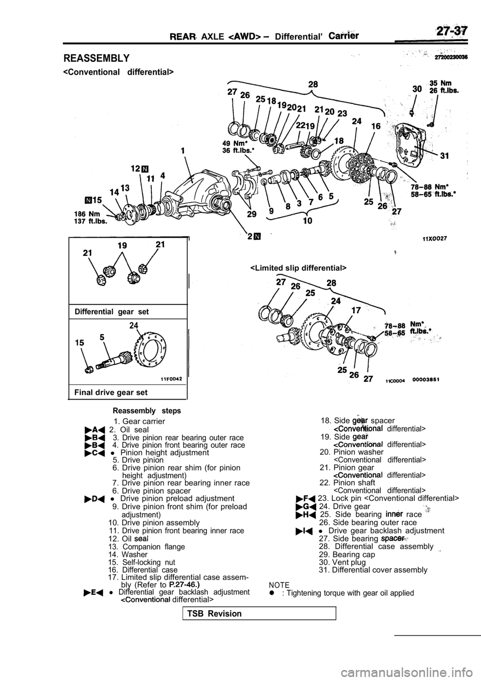
REASSEMBLY
Differential gear set
24
Final drive gear set
Reassembly steps
1. Gear carrier
2. Oil seal3. Drive pinion rear bearing outer race4. Drive pinion front bearing outer race l Pinion height adjustment
5. Drive pinion
6. Drive pinion rear shim (for pinion
height adjustment)7. Drive pinion rear bearing inner race
6. Drive pinion spacer
l Drive pinion preload adjustment
9. Drive pinion front shim (for preload
adjustment)10. Drive pinion assembly11. Drive pinion front bearing inner race
12. Oil 13. Companion flange
14. Washer
15. Self-locking nut
16. Differential case
17. Limited slip differential case assem- bly (Refer to
l Differential gear backlash adjustment differential> 18. Side
spacer
differential>
19. Side differential>20. Pinion washer
24. Drive gear 25. Side bearing race
26. Side bearing outer race
l
Drive gear backlash adjustment
27. Side bearing
28. Differential case assembly
29. Bearing cap
30. Vent plug
31. Differential cover assembly
NOTEl : Tightening torque with gear oil applied
TSB Revision
Page 1827 of 2103
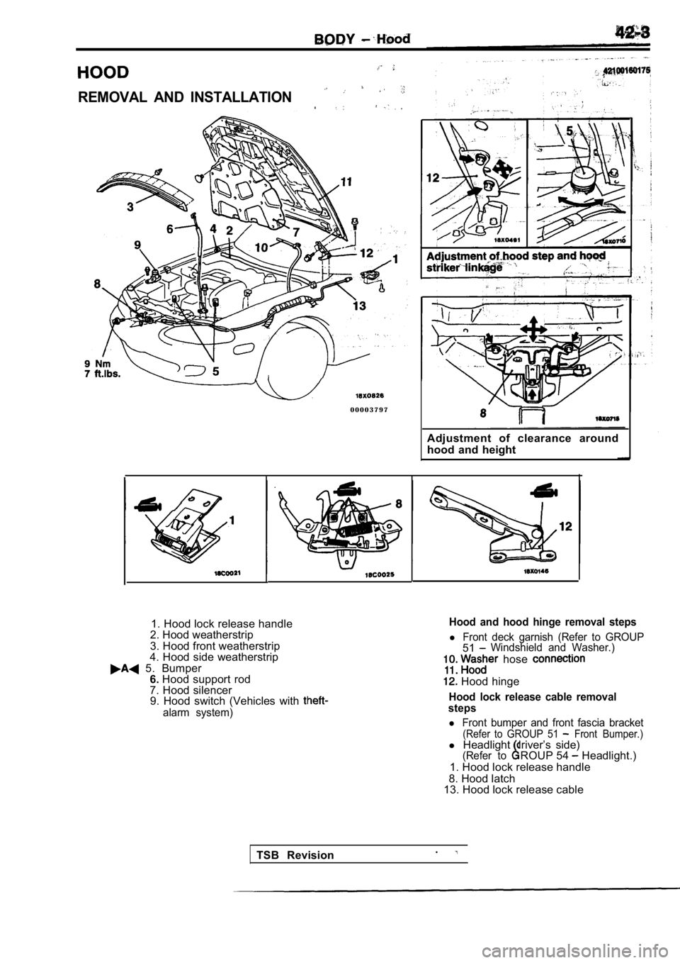
REMOVAL AND INSTALLATION
0 0 0 0 3 7 9 7Adjustment of clearance around
hood and height
1. Hood lock release handle
2. Hood weatherstrip
3. Hood front weatherstrip
4. Hood side weatherstrip
5. Bumper 6. Hood support rod
7. Hood silencer 9. Hood switch (Vehicles with
alarm system)
Hood and hood hinge removal steps
l Front deck garnish (Refer to GROUP51Windshield and Washer.)
hose
Hood hinge
Hood lock release cable removal
steps
l Front bumper and front fascia bracket(Refer to GROUP 51 Front Bumper.)l Headlight driver’s side)(Refer toROUP 54 Headlight.)
1. Hood lock release handle
8. Hood latch
13. Hood lock release cable
TSB Revision .