1990 MITSUBISHI SPYDER ESP inoperative
[x] Cancel search: ESP inoperativePage 741 of 2103

CONTENTS
AUTO-CRUISE CONTROL SYSTEM
. . . . . . . . . . . . . . . . . . . . . . . . . . . . . . . . . . . . .7
AUTO-CRUISE CONTROL* . . . . . . . . . . . . . . 40
GENERAL INFORMATION . . . . . . . . . . . . . . . . 7
ON-VEHICLE SERVICE. . . . . . . . . . . . . . . . . 33
Auto-cruise Control Cable Check and
Adjustment . . . . . . . . . . . . . . . . . . . . . . . . . . . . . .
33
Auto-cruise Control Component Check . . . . . 37
Auto-cruise Control System Operation Check
. . . . . . . . . . . . . . . . . . . . . . . . . . . . . . . . . . . . . . . . .
35
SERVICE SPECIFICATIONS . . . . . . . . . . . . . 8
SPECIAL TOOLS . . . . . . . . . . . . . . . . . . . . . . . . 8
TROUBLESHOOTING
ENGINE (NON-TURBO)> . . . . . . . . . . . 9
TROUBLESHOOTING
(TURBO) AND ENGINE> . . . . .
EMISSION CONTROL’ SYSTEM
. . . . .
CATALYTIC . . . . . . . . . . . . . .
General Information . . . . . . . . . . . . . . . . . . 57
EVAPORATIVE EMISSION .
SYSTEM. . . . . . . . . . . . . . . .
Air Conditioning . . . . . . . . . . . . . . . . . . . 52
Component Location
. . . . . . . . . . . . . . . . . .
Engine Coolant Temperature Sensor
Intake Air Temperature Sensor . . . . . . . . . . . . 52
WARNINGS REGARDING SERVICING OF SUPPLEMENTAL RESTRA INT SYSTEM (SRS) EQUIPPED
WARNING!
(1) Improper serviceor maintenance of any component of the or any SRS-related can to injuryorcleathtoservicepersonnel (from inadvertentfiring the SRS inoperative).
(2) Service or maintenance of any SRS component or SRS-related component must be performed only
MITSUBISHI dealer.
(3) MITSUBISHI dealer personnel must thoroughly rev iew this manual, and especially its GROUP
Restraint System (SRS) and GROUP 00 Maintenance Service, before any service or maintenance of any
componentof the SRS or any SRS-related component.
NOTEJhe includes the following components: warning light, air bag module, clock components (that may have to be removed/installed in connection with or areIndicated in the table of contents by an asterisk
Page 859 of 2103

CONTENTS
MANUAL TRANSAXLE ENGINEMANUAL TRANSAXLE ENGINE
(NON-TURBO)>(TURBO) AND ENGINE>
GENERAL INFORMATION . . . . . . . . . . . . . . 22GENERAL INFORMATION . . . . . . . . . . . . . . . .
2
LUBRICANTS. . . . . . . . . . . . . . . . . . . . . . . . . . 24LUBRICANTS. . . . . . . . . . . . . . . . . . . . . . . . . . .6
ON-VEHICLE SERVICE. . . . . . . . . . . . . . . . .
2 4
Transaxle Oil Level Check . . . . . . . . . . . . . . . .
24
Transaxle Oil Replacement . . . . . . . . . . . . . . .
24
SERVICE SPECIFICATIONS. . . . . . . . . . . . .24
SPECIAL TOOLS. . . . . . . . . . . . . . . . . . . . . . .24
TRANSAXLE ASSEMBLY. . . . . . . . . . . . . . .28
TRANSAXLE CONTROL*. . . . . . . . . . . . . . . .25ON-VEHICLE SERVICE
. . . . . . . . . . . . . . . . 8
Shift Lever Assembly
. . . . . . . . . . . . . . . . . . . . .
27
TROUBLESHOOTING. . . . . . . . . . . . . . . . . . .24
Transaxle Oil Level Check . . . . . . . . . . . . . . . . .8
Transaxle Oil Replacement
. . . . . . . . . . .. . .
Transfer Oil Level Check ...... . . . . . . . . . . .
Transfer Oil Replacement. . . . . . . . . . . . . . . . . .8
SERVICE SPECIFICATIONS. . . . . . . . . . ...
SPECIAL TOOLS 7. . . . . . . . . . . . . . . . . .
TRANSAXLE ASSEMBLY
. . . . . . . . . . . . . . . . . . . . ... . . .
. . . . . . . . . . . . . . . . . . . . . . . . . . . .
. . 1 2
TRANSAXLE CONTROL*... . . . . . . . .
Shift Lever Assembly. . . . . . . . . . . . . . . . . . . . . .1 1
TRANSFER ASSEMBLY . . . . . . . .
TROUBLESHOOTING . . . . . . . . . . . . . . . . . .
WARNINGS REGARDING SERVICING OF SUPPLEMENTAL RESTRA
INT SYSTEM (SRS) EQUIPPED VEHICLES
WARNING!
(1)Improper service or maintenance of any component of the or any component, can lead to personalinjury or death to service personnel (from inadvertent firing of the air bag) or to the driver and passenger (from
rendering the inoperative).Service or maintenance of any or component must be performed only at an authorized MITSUBISHI dealer.(3)MITSUBISHI dealer personnel must thoroughly review this manual,and especially its GROUP
Restraint System and GROUP 00 Maintenance Service, before beginning any or maintenance of
any component of the or any component.
NOTEThe SRS includes the following components: warning light, air bag module,clock spring, and interconnecting
wiring. Other
components (that may have to be removed/installed in connection with service or maintenance)
are indicated in the table of contents by an asterisk
Page 1009 of 2103
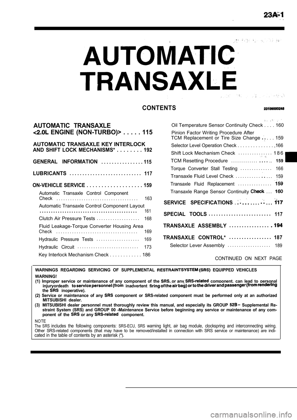
CONTENTS
AUTOMATIC TRANSAXLE
ENGINE (NON-TURBO)> . . . . . 115
AUTOMATIC TRANSAXLE KEY INTERLOCK
AND SHIFT LOCK MECHANISMS* . . . . . . . . 192
GENERAL INFORMATION
. . . . . . . . . . . . . . . . 115
LUBRICANTS. . . . . . . . . . . . . . . . . . . . . . . . . . . .117
ON-VEHICLE SERVICE . . . . . . . . . . . . . . . . . . . 159
Automatic Transaxle Control Component
Oil Temperature Sensor Continuity Check . . . . 160
Pinion Factor Writing Procedure After
TCM Replacement or Tire Size Change
. . . 159
Selector Level Operation Check . . . . . . . . . . . . . . ,166
Shift Lock Mechanism Check. . . . . . . . . . . . . . .
1 8 6
TCM Resetting Procedure . . . . . . . . . . . . .
..159
Torque Converter Stall Testing. . . . . . . . . . . . . .166
Transaxle Fluid Level Check . . . . . . . . . . .. . .159
Transaxle Fluid Replacement. . . . . . . . . . . . . . .
Transaxle Range Sensor Continuity . . .
Check. . . . . . . . . . . . . . . . . . . . . . . . . . . . . . . . . . . .163SERVICE SPECIFICATIONS.. . . .. . .Automatic Transaxle Control Component Layout
. . . . . . . . . . . . . . . . . . . . . . . . . . . . . . . . . . . . . . . . . . .
161SPECIAL TOOLS. . . . . . . . . . . . . . . . . . . . . . . . .117Clutch Air Pressure Tests . . . . . . . . . . . . . . . . . . .168
Fluid Leakage-Torque Converter Housing Area
Check. . . . . . . . . . . . . . . . . . . . . . . . . . . . . . . . . . . .169
Hydraulic Pressure Tests. . . . . . . . . . . . . . . . . . .169
Hydraulic Circuit. . . . . . . . . . . . . . . . . . . . . . . . . . .173
TRANSAXLE ASSEMBLY. . . . . . . . . . . . . . . .
TRANSAXLE CONTROL*. . . . . . . . . . . . . . . . .187
Selector Lever Assembly. . . . . . . . . . . . . . . . . . .189
Key Interlock Mechanism Check . . . . . . . . . . .
. 186CONTINUED ON NEXT PAGE
WARNINGS REGARDING SERVICING OF SUPPLEMENTAL EQUIPPED VEHICLES
WARNING! (1) Improper service or maintenance of any componen t of the
or any component, can lead to personal
injuryordeath inadvertent the inoperative).
(2) Service or maintenance of any component or SRS-related component must be perform ed only at an authorized
MITSUBISHI dealer.
(3)MITSUBISHI dealer personnel must thoroughly review this manual, and especially its GROUP Supplemental Re-
straint System (SRS) and GROUP 00 -Maintenance Serv ice before beginning any service or maintenance of any com-
ponent of the
or any component.
NOTEThe SRS includes the following components: SRS-ECU, SRS warning light, air bag module, clockspring and inte rconnecting wiring.Other SRS-related components (that may have to be removed/installed in connection with SRS service or maintenance) are indi-cated in the table of contents by an asterisk
Page 1176 of 2103
AUTOMATIC TRANSAXLE
ENGINE On-vehicle Service
Accumulators
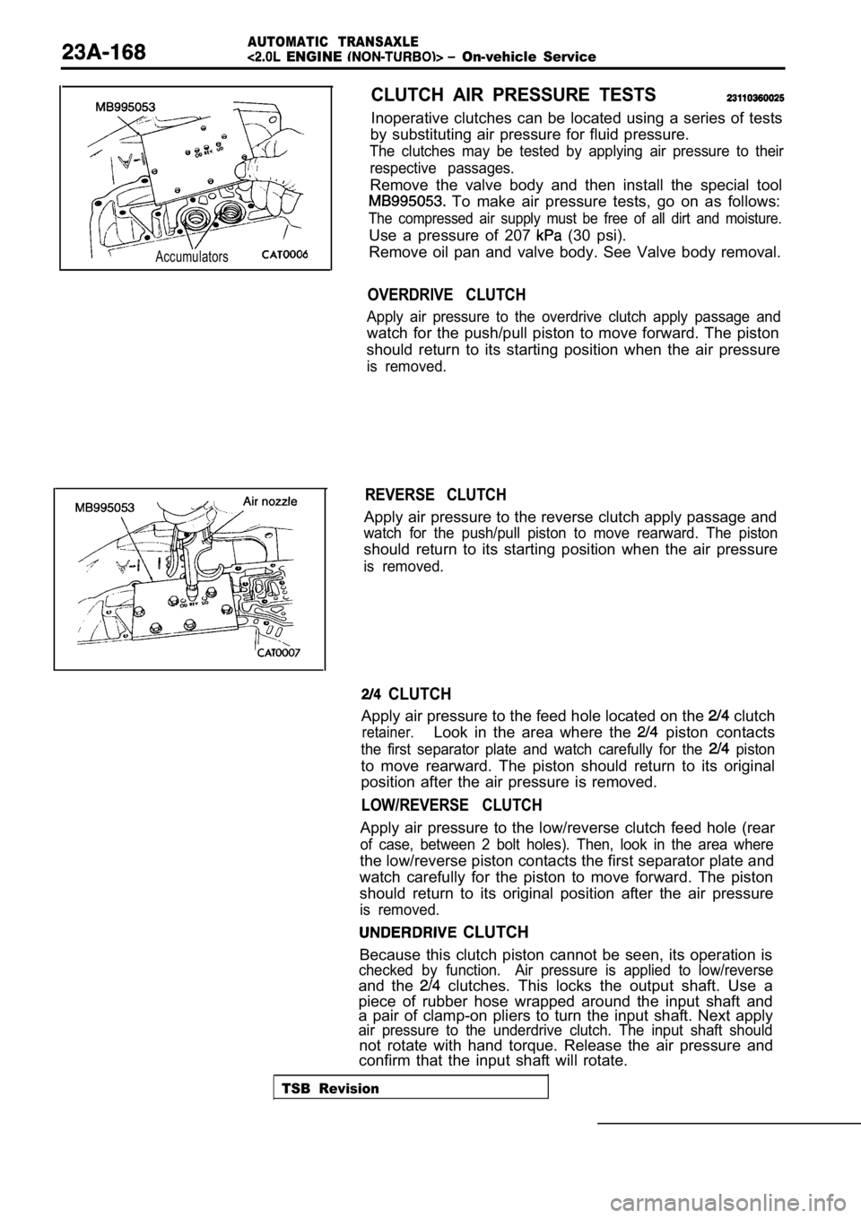
CLUTCH AIR PRESSURE TESTS
Inoperative clutches can be located using a series of tests
by substituting air pressure for fluid pressure.
The clutches may be tested by applying air pressure to their
respective passages.
Remove the valve body and then install the special tool
To make air pressure tests, go on as follows:
The compressed air supply must be free of all dirt and moisture.
Use a pressure of 207 (30 psi).
Remove oil pan and valve body. See Valve body remov al.
OVERDRIVE CLUTCH
Apply air pressure to the overdrive clutch apply passage and
watch for the push/pull piston to move forward. The piston
should return to its starting position when the air pressure
is removed.
REVERSE CLUTCH
Apply air pressure to the reverse clutch apply pass age and
watch for the push/pull piston to move rearward. Th e piston
should return to its starting position when the air pressure
is removed.
CLUTCH
Apply air pressure to the feed hole located on the clutch
retainer.Look in the area where the piston contacts
the first separator plate and watch carefully for the piston
to move rearward. The piston should return to its o riginal
position after the air pressure is removed.
LOW/REVERSE CLUTCH
Apply air pressure to the low/reverse clutch feed h ole (rear
of case, between 2 bolt holes). Then, look in the a rea where
the low/reverse piston contacts the first separator plate and
watch carefully for the piston to move forward. The piston
should return to its original position after the ai r pressure
is removed.
CLUTCH
Because this clutch piston cannot be seen, its oper ation is
checked by function. Air pressure is applied to low/ reverse
and the clutches. This locks the output shaft. Use a
piece of rubber hose wrapped around the input shaft and
a pair of clamp-on pliers to turn the input shaft. Next apply
air pressure to the underdrive clutch. The input sh aft should
not rotate with hand torque. Release the air pressu re and
confirm that the input shaft will rotate.
TSB Revision
Page 1763 of 2103
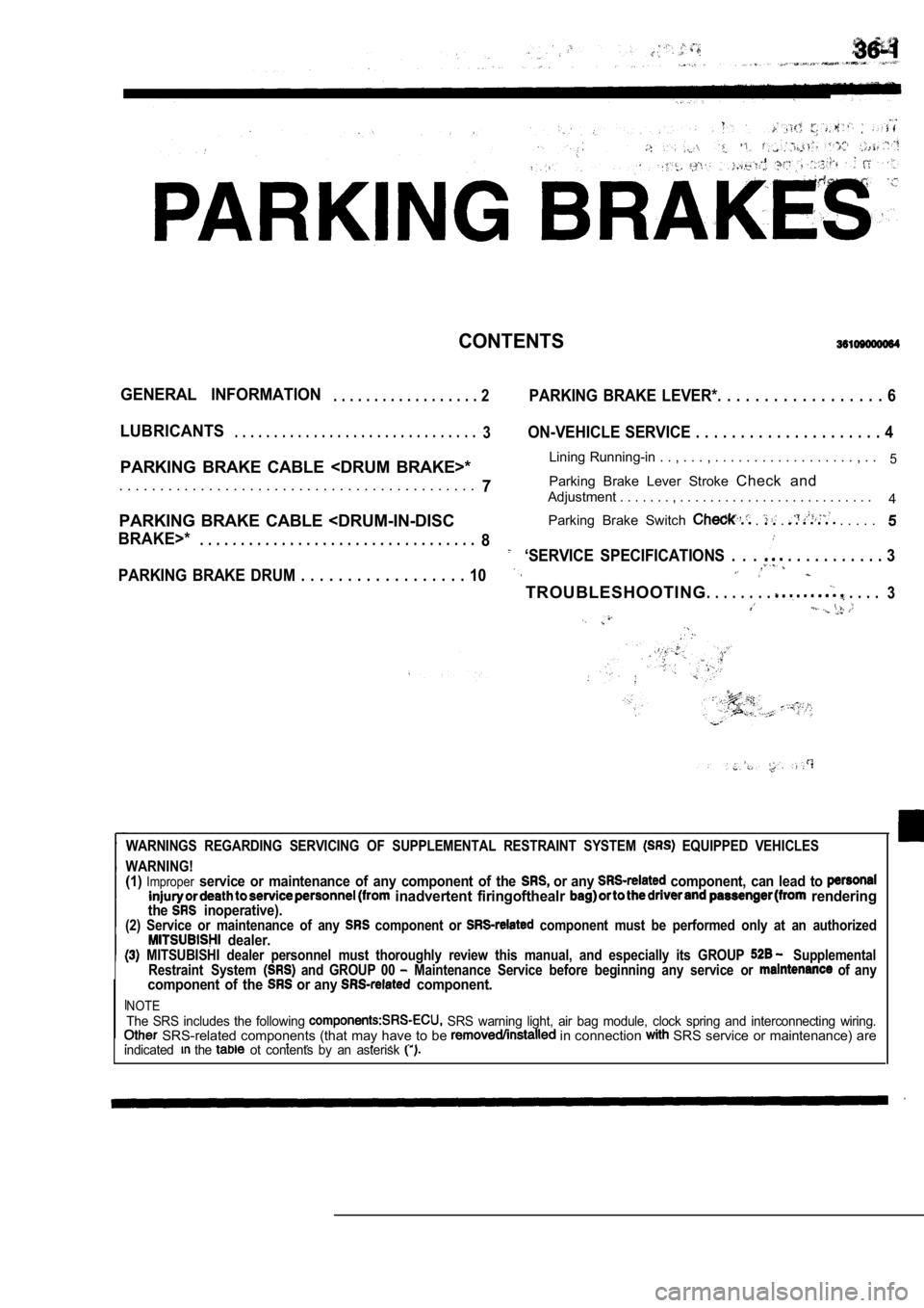
CONTENTS
GENERAL INFORMATION. . . . . . . . . . . . . . . . . . 2PARKING BRAKE LEVER*. . . . . . . . . . . . . . . . . . 6
LUBRICANTS. . . . . . . . . . . . . . . . . . . . . . . . . . . . . . .3ON-VEHICLE SERVICE . . . . . . . . . . . . . . . . . . . . . 4
PARKING BRAKE CABLE
. . . . . . . . , . .5
7Parking Brake Lever Stroke
Check and. . . . . . . . . . . . . . . . . . . . . . . . . . . . . . . . . . . . . . . . . . . .Adjustment . . . . . . . , . . . . . . . . . . . . . . . . . . . . . . . . . .
4
PARKING BRAKE CABLE
BRAKE>*. . . . . . . . . . . . . . . . . . . . . . . . . .
. . . . . . . .8‘SERVICE SPECIFICATIONS . . . . . . . . . . . . . . 3
PARKING BRAKE DRUM . . . . . . . . . . . . . . . . . . 10
TROUBLESHOOTING. . . . . . . . . . . . .
3
WARNINGS REGARDING SERVICING OF SUPPLEMENTAL RESTRA INT SYSTEM EQUIPPED VEHICLES
WARNING!
(1)Improperservice or maintenance of any component of the or any component, can lead to inadvertent firingofthealr renderingthe inoperative).(2) Service or maintenance of any component or component must be performed only at an authorized dealer. MITSUBISHI dealer personnel must thoroughly review this manual, and especially its GROUP Supplemental
Restraint System and GROUP 00 Maintenance Service before beginning any service o r of anycomponent of the or any component.
NOTEThe SRS includes the following SRS warning light, air bag module, clock spring and interconnecting wiring. SRS-related components (that may have to be in connection SRS service or maintenance) are
.. . . indicated the ot contents by an asterisk
Page 1775 of 2103
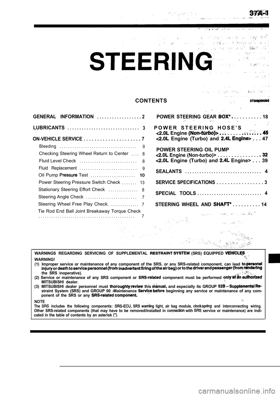
CONTENTS
GENERAL INFORMATION. . . . . . . . . . . . . . . . . . 2POWER STEERING GEAR . . . . . . . . . . 18
LUBRICANTS. . . . . . . . . . . . . . . . . . . . . . . . . . . . . .
3P O W E R S T E E R I N G H O S E ’ S
Engine . . . . .
ON-VEHICLE SERVICE . . . . . . . . . . . . . . . . . . . . . 7 Engine (Turbo) and . . . 47
Bleeding. . . . . . . . . . . . . . . . . . . . . . . . . . . . . . . . . . . .9
Checking Steering Wheel Return to Center
. . . .8
Fluid Level Check. . . . . . . . . . . . . . . . . . . . . . . . . . .8
Fluid Replacement. . . . . . . . . . . . . . . . . . . . . . . . . . .9
Oil Pump Test
. . . . . . . . . . . . . . . . . . . . .
Power Steering Pressure Switch Check
. . . . . . .13
Stationary Steering Effort Check. . . . . . . . . . . . . .8
Steering Angle Check. . . . . . . . . . . . . . . . . . . . . . . .7
Steering Wheel Free Play Check. . . . . . . . . . . . . . .7
Tie Rod End Ball Joint Breakaway Torque Check
. . . . . . . . . . . . . . . . . . . . . . . . . . . . . . . . . . . . . . . . . . . . .
7
POWER STEERING OIL PUMP
Engine (Non-turbo)> . . . . . . . . . . . . . . .
Engine (Turbo) and Engine> . . . 39
SEALANTS. . . . . . . . . . . . . . . . . . . . . . . . . . . . . . . .4
SERVICE SPECIFICATIONS . . . . . . . . . . . . . . . . . 3
SPECIAL TOOLS. . . . . . . . . . . . . . . . . . . . . . . . . . .4
STEERING WHEEL AND
. . . . . . . . . . 14
WARNINGS REGARDING SERVICING OF SUPPLEMENTAL (SRS) EQUIPPED
WARNING!(1)Improper service or maintenance of any component of the SRS, or any SRS-related component, can lead
the SRS inoperative).(2) Service or maintenance of any SRS component or component must be performed MITSUBISHI dealer.(3) MITSUBISHI dealer personnel must this and especially its GROUP straint System (SRS) and GROUP 00 -Maintenance beginning any service or maintenance of any com-
ponent of the SRS or any
NOTEThe includes the following components: SRS light, air bag module, and interconnecting wiring.Other SRS-related components (that may have to be r emoved/installed in with service or maintenance) are indi-
cated in the table of contents by an asterisk
Page 1931 of 2103
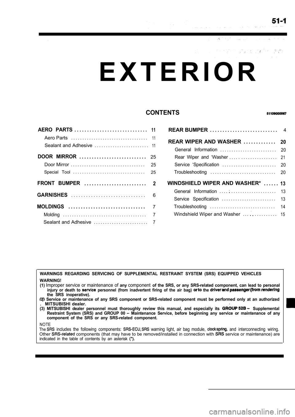
E X T E R I O R
CONTENTS
AERO PARTS. . . . . . . . . . . . . . . . . . . . . . . . . . . . .11REAR BUMPER. . . . . . . . . . . . . . . . . . . . . . . . . . .4
Aero Parts . . . . . . . . . . . . . . . . . . . . . . . . . . . . . . . . . .
11REAR WIPER AND WASHER . . . . . . . . . . . . .20Sealant and Adhesive . . . . . . . . . . . . . . . . . . . . . . . .11General Information. . . . . . . . . . . . . . . . . . . . . . . . .20
DOOR MIRROR. . . . . . . . . . . . . . . . . . . . . . . . . . . 25Rear Wiper and ‘Washer. . . .. . . . . . . . . . . . . . . . .21
Door Mirror . . . . . . . . . . . . . . . . . . . . . . . . . . . . . . . . .25Service ‘Specification. . . . . . . . . . . . . . . . . . . . . . . .20
Special Tool . . . . . . . . . . . . . . . . . . . . . . . . . . . . . . . .
25Troubleshooting. . . . . . . . . . . . . . . . . . . . . . . . . . . . .20
FRONT BUMPER. . . . . . . . . . . . . . . . . . . . . . . . .2WINDSHIELD WIPER AND WASHER* . . . . . .13
6General Information. . . .. . . . . . . . . . . . . . . . . . . .13GARNISHES. . . . . . . . . . . . . . . . . . . . . . . . . . . . . .Service Specification. . . . . . . . . . . . . . . . . . . . . . . .13
MOLDINGS. . . . . . . . . . . . . . . . . . . . . . . . . . . . . . .7Troubleshooting. . . . . . . . . . . . . . . . . . . . . . . . . . . . .14
Molding. . . . . . . . . . . . . . . . . . . . . . . . . . . . . . . . . . . . .7Windshield Wiper and Washer . . .. . . . . . . . . .15
Sealant and Adhesive . . . . . . . . . . . . . . . . . . . . . . . .7
WARNINGS REGARDING SERVICING OF SUPPLEMENTAL RESTRA INT SYSTEM (SRS) EQUIPPED VEHICLES
WARNING! (1)
Improper service or maintenance of anycomponentof the SRS, or any SRS-related component, can lead to personalinjury or death to personnel (from inadvertent firing of the air bag) the the SRS inoperative). Service or maintenance of any SRS component or SRS -related component must be performed only at an authorized. MITSUBISHI dealer.(3) MITSUBISHI dealer personnel must thoroughly rev iew this manual, and especially its Supplemental
Restraint System (SRS) and GROUP 00 Maintenance Service, before beginning any service or maintenance of any
component of the SRS or any SRS-related component.
NOTE
The includes the following components: warning light, air bag module, and interconnecting wiring.Other components (that may have to be removed/installed in connection with service or maintenance) areindicated in the table of contents by an asterisk
Page 1959 of 2103
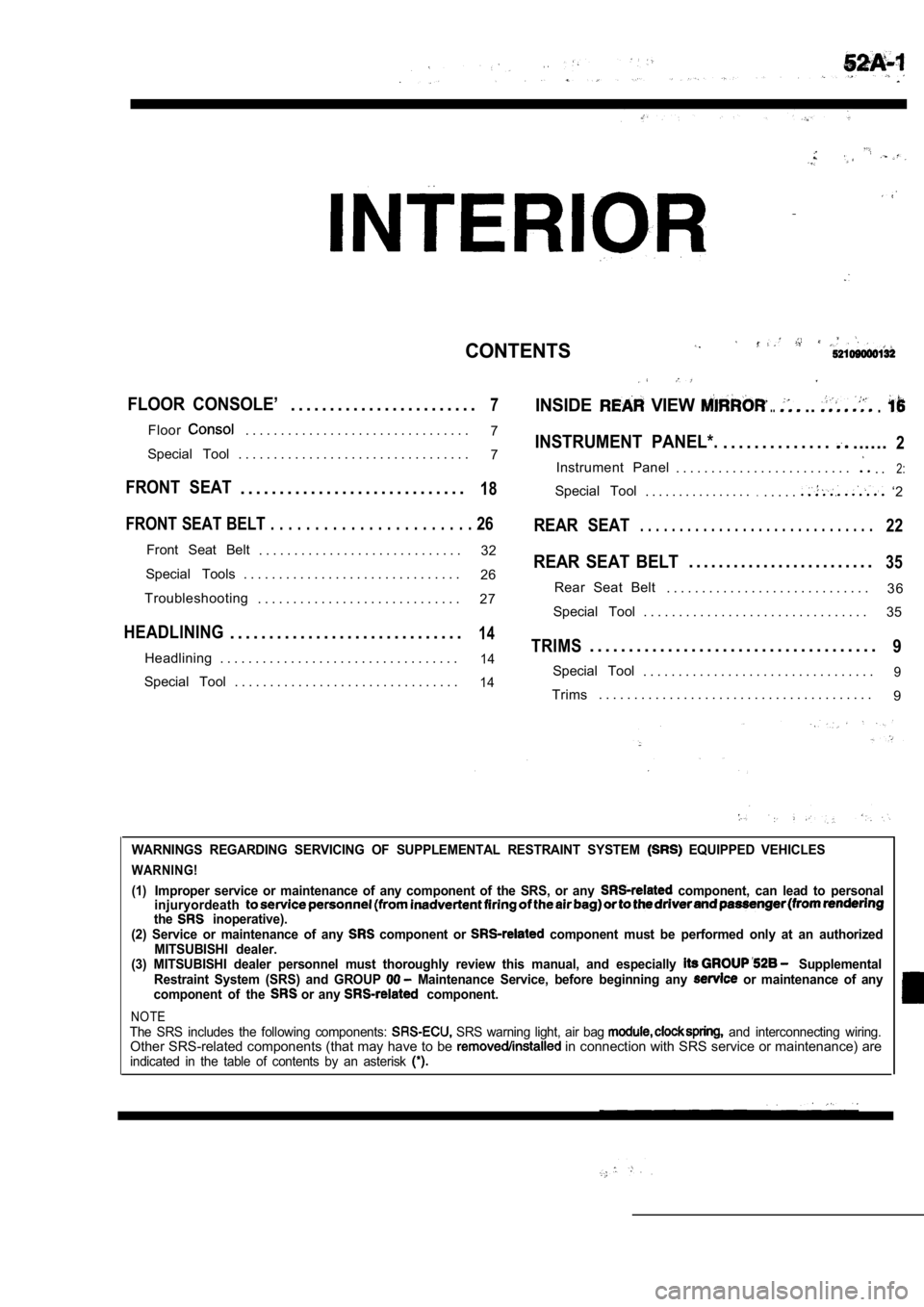
CONTENTS
FLOOR CONSOLE’. . . . . . . . . . . . . . . . . . . . . . . .7INSIDE VIEW .....
Floor. . . . . . . . . . . . . . . . . . . . . . . . . . . . . . . .7INSTRUMENT PANEL*.. . . . . . . . . . . . . .......2Special Tool . . . . . . . . . . . . . . . . . . . . . . . . . . . . . . . . . 7
Instrument Panel . . . . . . . . . . . . . . . . . . . . . . . . .. .2:
FRONT SEAT. . . . . . . . . . . . . . . . . . . . . . . . . . . . .18Special Tool. . . . . . . . . . . . . . . ... . . . .. ‘2
FRONT SEAT BELT . . . . . . . . . . . . . . . . . . . . . . . 26REAR SEAT. . . . . . . . . . . . . . . . . . . . . . . . . . . . . .22
Front Seat Belt
. . . . . . . . . . . . . . . . . . . . . . . . . . . . . 32REAR SEAT BELT. . . . . . . . . . . . . . . . . . . . . . . . .35Special Tools . . . . . . . . . . . . . . . . . . . . . . . . . . . . . . .
26
3 6
Troubleshooting Rear Seat Belt
. . . . . . . . . . . . . . . . . . . . . . . . . . . . .
. . . . . . . . . . . . . . . . . . . . . . . . . . . . . 27
Special Tool . . . . . . . . . . . . . . . . . . . . . . . . . . . . . . . . 35
HEADLINING. . . . . . . . . . . . . . . . . . . . . . . . . . . . . .14TRIMS. . . . . . . . . . . . . . . . . . . . . . . . . . . . . . . . . . . . .9Headlining . . . . . . . . . . . . . . . . . . . . . . . . . . . . . . . . . .14Special Tool. . . . . . . . . . . . . . . . . . . . . . . . . . . . . . . . .9Special Tool . . . . . . . . . . . . . . . . . . . . . . . . . . . . . . . .14Trims. . . . . . . . . . . . . . . . . . . . . . . . . . . . . . . . . . . . . . .
9
WARNINGS REGARDING SERVICING OF SUPPLEMENTAL RESTRA INT SYSTEM EQUIPPED VEHICLES
WARNING!
(1)
Improper service or maintenance of any component of the SRS, or any component, can lead to personal
injuryordeath
the inoperative).
(2) Service or maintenance of any component or component must be performed only at an authorized
MITSUBISHI dealer.
(3) MITSUBISHI dealer personnel must thoroughly rev iew this manual, and especially
Supplemental
Restraint System (SRS) and GROUP Maintenance Service, before beginning any or maintenance of any
component of the or any component.
NOTEThe SRS includes the following components: SRS warning light, air bag and interconnecting wiring.Other SRS-related components (that may have to be in connection with SRS service or maintenance) areindicated in the table of contents by an asterisk