1990 MITSUBISHI SPYDER power steering fluid
[x] Cancel search: power steering fluidPage 3 of 2103
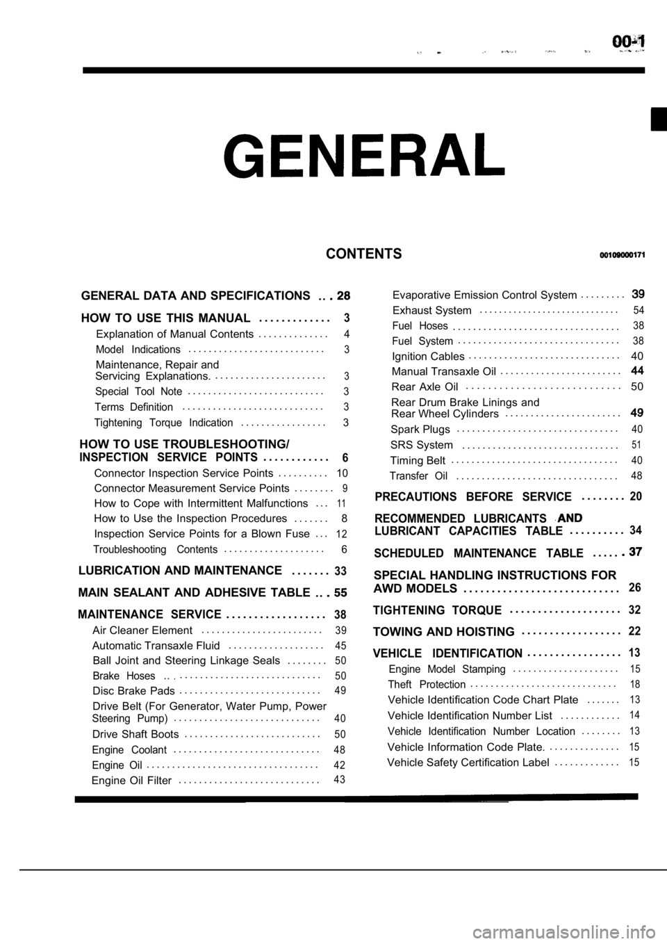
CONTENTS
GENERAL DATA AND SPECIFICATIONS. .
HOW TO USE THIS MANUAL. . . . . . . . . . . . .3
Explanation of Manual Contents. . . . . . . . . . . . . .4
Model Indications
. . . . . . . . . . . . . . . . . . . . . . . . . . .3
Maintenance, Repair and
Servicing Explanations. . . . . . . . . . . . . . . . . . . . . . .
3
Special Tool Note. . . . . . . . . . . . . . . . . . . . . . . . . . .3
Terms Definition. . . . . . . . . . . . . . . . . . . . . . . . . . . .3
Tightening Torque Indication. . . . . . . . . . . . . . . . .3
HOW TO USE TROUBLESHOOTING/
INSPECTION SERVICE POINTS. . . . . . . . . . . .6
Connector Inspection Service Points
. . . . . . . . . .10
Connector Measurement Service Points . . . . . . . .9
How to Cope with Intermittent Malfunctions . . .11
How to Use the Inspection Procedures
. . . . . . .
8
Inspection Service Points for a Blown Fuse . . .
12
Troubleshooting Contents. . . . . . . . . . . . . . . . . . . .6
LUBRICATION AND MAINTENANCE . . . . . . .33
MAIN SEALANT AND ADHESIVE TABLE
. .
MAINTENANCE SERVICE. . . . . . . . . . . . . . . . . .38
Air Cleaner Element. . . . . . . . . . . . . . . . . . . . . . . .39
Automatic Transaxle Fluid
. . . . . . . . . . . . . . . . . . .45
Ball Joint and Steering Linkage Seals
. . . . . . . .50
Brake Hoses.... . . . . . . . . . . . . . . . . . . . . . . . . . . .50
Disc Brake Pads. . . . . . . . . . . . . . . . . . . . . . . . . . . .49
Drive Belt (For Generator, Water Pump, Power
Steering Pump). . . . . . . . . . . . . . . . . . . . . . . . . . . . .40
Drive Shaft Boots
. . . . . . . . . . . . . . . . . . . . . . . . . . .50
Engine Coolant. . . . . . . . . . . . . . . . . . . . . . . . . . . . .48
Engine Oil. . . . . . . . . . . . . . . . . . . . . . . . . . . . . . . . . .42
Engine Oil Filter. . . . . . . . . . . . . . . . . . . . . . . . . . . .43
Evaporative Emission Control System . . . . . . . . .
Exhaust System. . . . . . . . . . . . . . . . . . . . . . . . . . . . .54
Fuel Hoses. . . . . . . . . . . . . . . . . . . . . . . . . . . . . . . . .38
Fuel System. . . . . . . . . . . . . . . . . . . . . . . . . . . . . . . .38
Ignition Cables. . . . . . . . . . . . . . . . . . . . . . . . . . . . . .
40
Manual Transaxle Oil . . . . . . . . . . . . . . . . . . . . . . . .
Rear Axle Oil. . . . . . . . . . . . . . . . . . . . . . . . . . . .
50
Rear Drum Brake Linings and
Rear Wheel Cylinders . . . . . . . . . . . . . . . . . . . . . . .
Spark Plugs. . . . . . . . . . . . . . . . . . . . . . . . . . . . . . . .40
SRS System . . . . . . . . . . . . . . . . . . . . . . . . . . . . . . .51
Timing Belt. . . . . . . . . . . . . . . . . . . . . . . . . . . . . . . . .40
Transfer Oil. . . . . . . . . . . . . . . . . . . . . . . . . . . . . . . .48
PRECAUTIONS BEFORE SERVICE. . . . . . . .20
RECOMMENDED LUBRICANTS
LUBRICANT CAPACITIES TABLE. . . . . . . . . .34
SCHEDULED MAINTENANCE TABLE. . . . .
SPECIAL HANDLING INSTRUCTIONS FOR
AWD MODELS . . . . . . . . . . . . . . . . . . . . . . . . . . . .
26
TIGHTENING TORQUE. . . . . . . . . . . . . . . . . . . .32
TOWING AND HOISTING . . . . . . . . . . . . . . . . . .22
VEHICLE IDENTIFICATION. . . . . . . . . . . . . . . . .13
Engine Model Stamping. . . . . . . . . . . . . . . . . . . . .15
Theft Protection. . . . . . . . . . . . . . . . . . . . . . . . . . . . .18
Vehicle Identification Code Chart Plate
. . . . . . .13
Vehicle Identification Number List. . . . . . . . . . . .14
Vehicle Identification Number Location. . . . . . . .13
Vehicle Information Code Plate.. . . . . . . . . . . . . .15
Vehicle Safety Certification Label
. . . . . . . . . . . . .15
Page 36 of 2103
Lubrication and
GENERAL Lubricants and Lubricant Capacities Table
Use of fuels containing alcohol is not recommended
unless the nature of the blend can be determined
as being satisfactory.
Gasohol
A mixture of 10% ethanol (grain alcohol)
and 90% unleaded gasoline may be used in your
car.
If problems are experienced as a result
of using gasohol, it is recommended that the car
be operated on gasoline.
Methanol Do not use gasolines containing
methanol (wood alcohol). Use of this type of alcohol
can result in vehicle performance deterioration and
damage critical parts in the fuel system compo-
nents. Fuel system damage and performance prob-
lems, resulting from the use of gasolines containin g
methanol, may not be covered by the new car war-
ranty.
Gasolines containing
Ether)
Unleaded gasoline containing 15% or
may be used in car. Fuel containing MTBE
over 15% vol. may cause reduced engine perfor-
mance and produce vapor lock or hard starting.
MATERIALS
TO FUEL
Indiscriminate use of fuel system -cleaning’
should be avoided. Many of these materials in-
tended for gum and varnish removal
highly active solvents or similar ingredients that
can be harmful to gasket and diaphragm materials
used in fuel system component
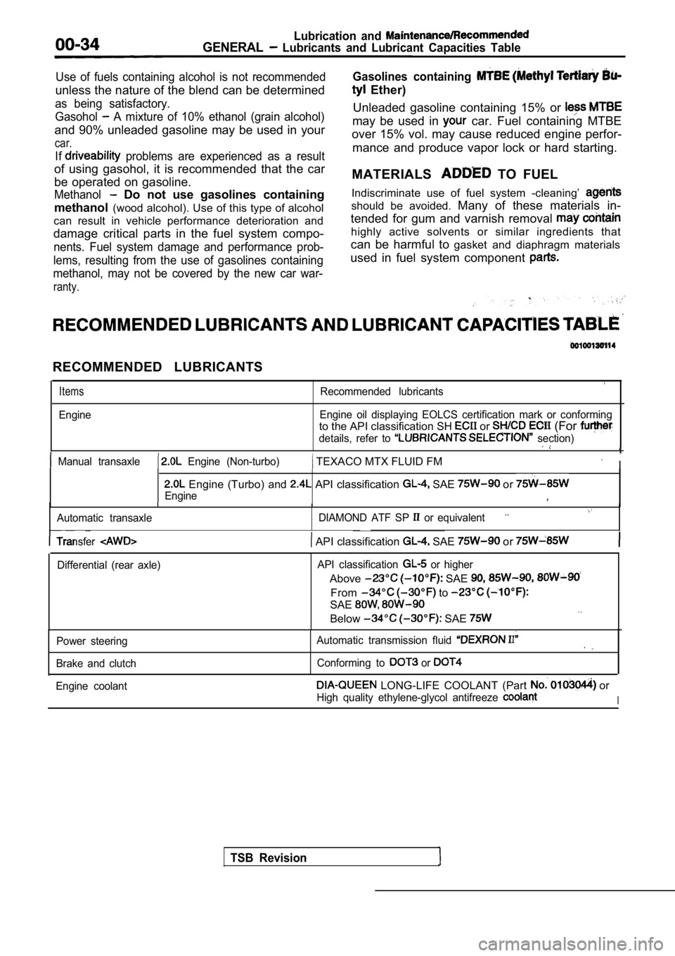
RECOMMENDED LUBRICANTS
Items
Engine
Recommended lubricants
Engine oil displaying EOLCS certification mark or c onforming
to the API classification SH or (For
details, refer to section)
Manual transaxle Engine (Non-turbo) TEXACO MTX FLUID FM I
Engine (Turbo) and API classification SAE or
Engine,
Automatic transaxle DIAMOND ATF SP or equivalent
TSB Revision
Transfer API classification SAE or
Differential (rear axle)API classification or higher
Above SAE
From to
SAE
Below SAE
Power steering
Brake and clutch Automatic transmission fluid
Conforming to or
Engine coolant LONG-LIFE COOLANT (Part or
High quality ethylene-glycol antifreeze I
Page 528 of 2103
ENGINE (TURBO)
AND
ENGINE> Troubleshooting
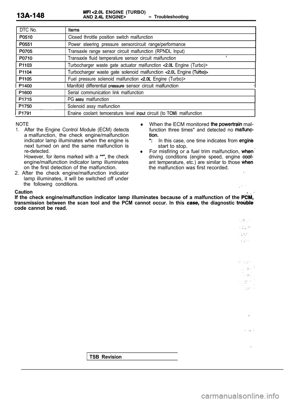
DTC No.
Closed throttle position switch malfunction
Power steering pressure sensorcircuit range/perfor mance
Transaxle range sensor circuit malfunction (RPNDL Input)
Transaxle fluid temperature sensor circuit malfunct ion
Turbocharger waste gate actuator malfunction Engine (Turbo)>
Turbocharger waste gate solenoid malfunction Engine
Fuel pressure solenoid malfunction Engine (Turbo)>
Manifold differential sensor circuit malfunction
Serial communication link malfunction
PG
malfunction
Solenoid assy malfunction
Enaine coolant temoerature level
circuit (to malfunction
NOTElWhen the ECM monitored mal-
1.After the Engine Control Module (ECM) detects function three times* and detected no
a malfunction, the check engine/malfunction
indicator lamp illuminates when the engine isIn this case, one time indicates from
next turned on and the same malfunction is
start to stop.
re-detected.lFor misfiring or a fuel trim malfunction,
However, for items marked with a the checkdriving conditions (engine speed, engine
engine/malfunction indicator lamp illuminatesant temperature, etc.) are similar to those
on the first detection of the malfunction. the malfunction was first recorded.
2. After the check engine/malfunction indicator
lamp illuminates, it will be switched off under
the following conditions.
Caution,
If the check engine/malfunction indicator lamp illu minates because of a malfunction of the
transmission between the scan tool and the PCM cann ot occur. In this the diagnostic
code cannot be read.
TSB Revision
Page 1599 of 2103
POWER PLANT MOUNT Crossmember
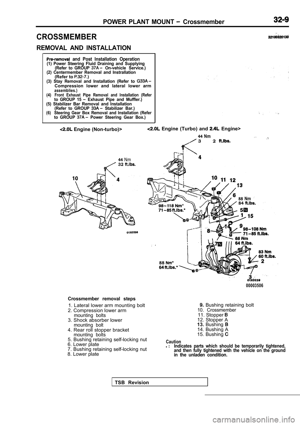
CROSSMEMBER
REMOVAL AND INSTALLATION
and Post Installation Operation(1) Power Steering Fluid Draining and Supplying(Refer to GROUP On-vehicle Service.)
(2) Centermember Removal and Instrallation
(Refer to (3) Stay Removal and Installation (Refer to Compression lower and lateral lower armassemblies.)(4)Front Exhaust Pipe Removal and Installation (Referto GROUP 15 Exhaust Pipe and Muffler.)
(5) Stabilizer Bar Removal and Installation (Refer to GROUP
Stabilizer Bar.)(6)Steering Gear Box Removal and Installation (Referto GROUP Power Steering Gear Box.)
Engine (Non-turbo)>
44Nm32
Engine (Turbo) and Engine>
44Nm3 2
88Nm84
88
00003506
Crossmember removal steps
1. Lateral lower arm mounting bolt
2. Compression lower arm
mounting bolts3. Shock absorber lowermounting bolt4. Rear roll stopper bracketmounting bolts5. Bushing retaining self-locking nut
6. Lower plate
7. Bushing retaining self-locking nut
8. Lower plate
Bushing retaining bolt10. Crossmember11. Stopper 12. Stopper A
13. Bushing
14. Bushing A
15. Bushing
Cautionl Indicates parts which should be temporarily tighten ed,
and then fully tightened with the vehicle on the gr ound
in the unladen condition.
TSB Revision
Page 1663 of 2103
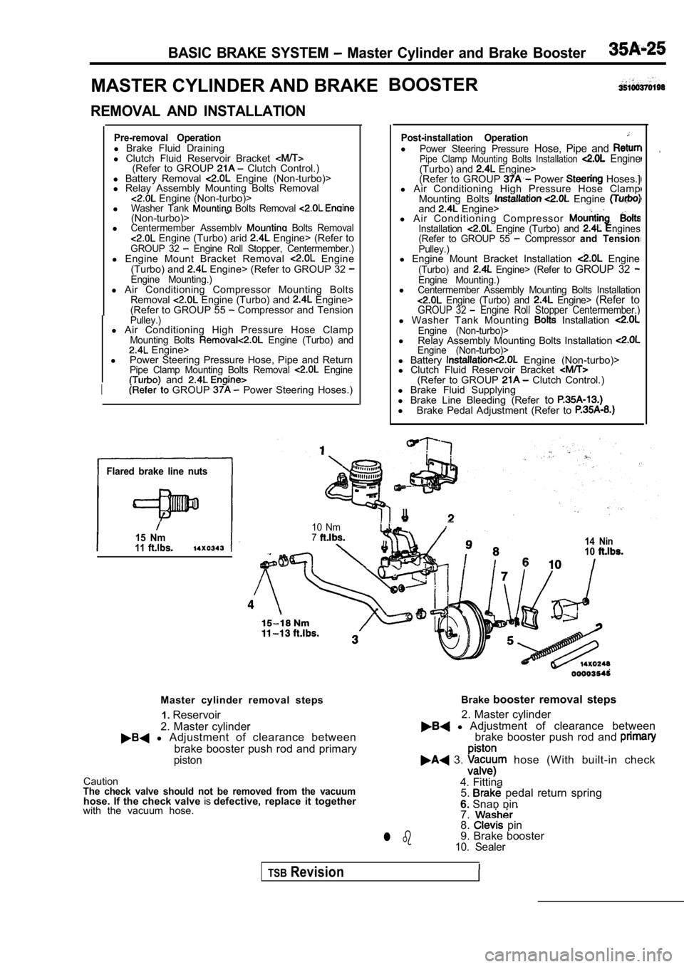
BASIC BRAKE SYSTEM Master Cylinder and Brake Booster
MASTER CYLINDER AND BRAKEBOOSTER
REMOVAL AND INSTALLATION
Pre-removal Operationl
Brake Fluid Draining
l Clutch Fluid Reservoir Bracket
(Refer to GROUP Clutch Control.)
l Battery Removal Engine (Non-turbo)>
l Relay Assembly Mounting Bolts Removal
Engine (Non-turbo)>
lWasher Tank Bolts Removal (Non-turbo)>lCentermember Assemblv Bolts Removal Engine (Turbo) arid Engine> (Refer toGROUP 32 Engine Roll Stopper, Centermember.)l Engine Mount Bracket Removal Engine
(Turbo) and Engine> (Refer to GROUP 32 Engine Mounting.)l Air Conditioning Compressor Mounting Bolts
Removal Engine (Turbo) and Engine>
(Refer to GROUP 55 Compressor and TensionPulley.)l Air Conditioning High Pressure Hose ClampMounting Bolts Engine (Turbo) and Engine>
l Power Steering Pressure Hose, Pipe and Return
Pipe Clamp Mounting Bolts Removal Engine and
I GROUP Power Steering Hoses.)
Flared brake line nuts
15 Nm11
Post-installation OperationlPower Steering Pressure Hose, Pipe and Pipe Clamp Mounting Bolts Installation Engine(Turbo) and Engine>
(Refer to GROUP Power Hoses.]
l Air Conditioning High Pressure Hose Clamp
Mounting Bolts
Engine and Engine>
l A i r C o n d i t i o n i n g C o m p r e s s o r
Installation Engine (Turbo) and ngines
(Refer to GROUP 55 Compressor and TensionPulley.)l Engine Mount Bracket Installation Engine(Turbo) and Engine> (Refer to GROUP 32 Engine Mounting.)lCentermember Assembly Mounting Bolts Installation Engine (Turbo) and Engine> (Refer toGROUP 32 Engine Roll Stopper Centermember.)l Washer Tank Mounting Installation Engine (Non-turbo)>l
Relay Assembly Mounting Bolts Installation Engine (Non-turbo)>l Battery Engine (Non-turbo)>
l Clutch Fluid Reservoir Bracket
(Refer to GROUP Clutch Control.)
l Brake Fluid Supplying
l Brake Line Bleeding (Refer to
l
Brake Pedal Adjustment (Refer to
I
10 Nm714 Nin10
Master cylinder removal steps
2. Master cylinder1.
Reservoir
l Adjustment of clearance between
brake booster push rod and primary
piston
CautionThe check valve should not be removed from the vacu umhose. If the check valve isdefective, replace it together
with the vacuum hose. Brake
booster removal steps
l Adjustment of clearance between
2. Master cylinder
brake booster push rod and
3. hose (With built-in check
4. Fittina 5.
pedal return spring
6. Snap pin
7.
8. pin
9. Brake booster
10. Sealerl b
TSBRevision
Page 1724 of 2103
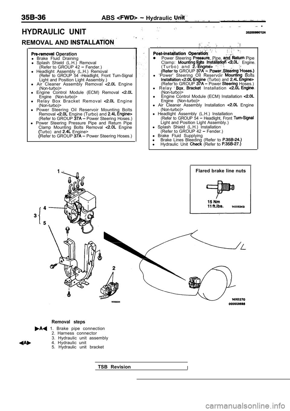
HYDRAULIC UNIT
ABS Hydraulic .
.
REMOVAL AND
.
Operationl Brake Fluid Draining
l Splash Shield (L.H.) Removal
(Refer to GROUP 42
Fender.)
l Headlight Assembly (L.H.) Removal
(Refer to GROUP 54 -Headlight, Front Turn-SignalLight and Position Light Assembly.)
l Air Cleaner Assembly Removal Engine(Non-turbo)>l Engine Control Module (ECM) Removal Engine (Non-turbo)>l R e l a y B o x B r a c k e t R e m o v a l E n g i n e(Non-turbo)>
Power Steering Pipe, Pipe
Clamp: Engine.( T u r b o ) a n d . GROUP l ‘Power‘ Steering Oil Reservoir Bolts (Turbo) and (Refer’to GROUP Power Hoses.)
l R e l a y Installation (Non-turbo)>l Engine Control Module (ECM) Installation Engine (Non-turbo)>l Air Cleaner Assembly Installation Engine(Non-turbo)>l Power Steering Oil Reservoir Mounting Bolts
Removal Engine (Turbo) and (Refer to GROUP Power Steering Hoses.)
l Power Steering Pressure Pipe and Return Pipe
Clamp Mounting Bolts Removal
EngineTurbo)and Engine>
Refer to GROUP Power Steering Hoses.) l
Headlight Assembly (L.H.) Installation
(Refer to GROUP 54 Headlight, Front Light and Position Light Assembly.)
l Splash Shield (L.H.) Installation
(Refer to GROUP 42
Fender.)
l Brake Fluid Supplying
l Brake Lines Bleeding (Refer to
lHydraulic Unit (Refer to
Flared brake line nuts
Removal steps
1. Brake pipe connection2.Harness connector
3. Hydraulic unit assembly
4. Hydraulic unit 5. Hydraulic unit bracket
TSB Revision
I
Page 1775 of 2103
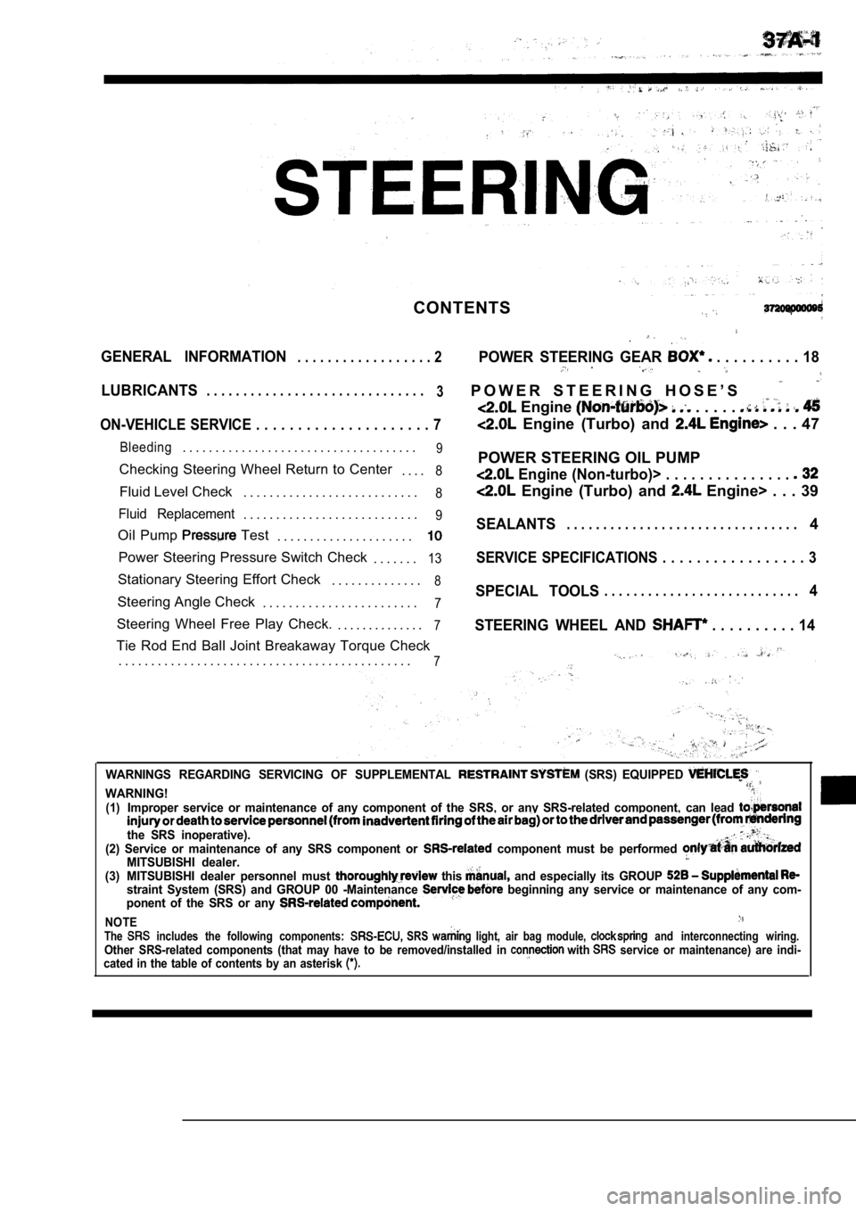
CONTENTS
GENERAL INFORMATION. . . . . . . . . . . . . . . . . . 2POWER STEERING GEAR . . . . . . . . . . 18
LUBRICANTS. . . . . . . . . . . . . . . . . . . . . . . . . . . . . .
3P O W E R S T E E R I N G H O S E ’ S
Engine . . . . .
ON-VEHICLE SERVICE . . . . . . . . . . . . . . . . . . . . . 7 Engine (Turbo) and . . . 47
Bleeding. . . . . . . . . . . . . . . . . . . . . . . . . . . . . . . . . . . .9
Checking Steering Wheel Return to Center
. . . .8
Fluid Level Check. . . . . . . . . . . . . . . . . . . . . . . . . . .8
Fluid Replacement. . . . . . . . . . . . . . . . . . . . . . . . . . .9
Oil Pump Test
. . . . . . . . . . . . . . . . . . . . .
Power Steering Pressure Switch Check
. . . . . . .13
Stationary Steering Effort Check. . . . . . . . . . . . . .8
Steering Angle Check. . . . . . . . . . . . . . . . . . . . . . . .7
Steering Wheel Free Play Check. . . . . . . . . . . . . . .7
Tie Rod End Ball Joint Breakaway Torque Check
. . . . . . . . . . . . . . . . . . . . . . . . . . . . . . . . . . . . . . . . . . . . .
7
POWER STEERING OIL PUMP
Engine (Non-turbo)> . . . . . . . . . . . . . . .
Engine (Turbo) and Engine> . . . 39
SEALANTS. . . . . . . . . . . . . . . . . . . . . . . . . . . . . . . .4
SERVICE SPECIFICATIONS . . . . . . . . . . . . . . . . . 3
SPECIAL TOOLS. . . . . . . . . . . . . . . . . . . . . . . . . . .4
STEERING WHEEL AND
. . . . . . . . . . 14
WARNINGS REGARDING SERVICING OF SUPPLEMENTAL (SRS) EQUIPPED
WARNING!(1)Improper service or maintenance of any component of the SRS, or any SRS-related component, can lead
the SRS inoperative).(2) Service or maintenance of any SRS component or component must be performed MITSUBISHI dealer.(3) MITSUBISHI dealer personnel must this and especially its GROUP straint System (SRS) and GROUP 00 -Maintenance beginning any service or maintenance of any com-
ponent of the SRS or any
NOTEThe includes the following components: SRS light, air bag module, and interconnecting wiring.Other SRS-related components (that may have to be r emoved/installed in with service or maintenance) are indi-
cated in the table of contents by an asterisk
Page 1776 of 2103
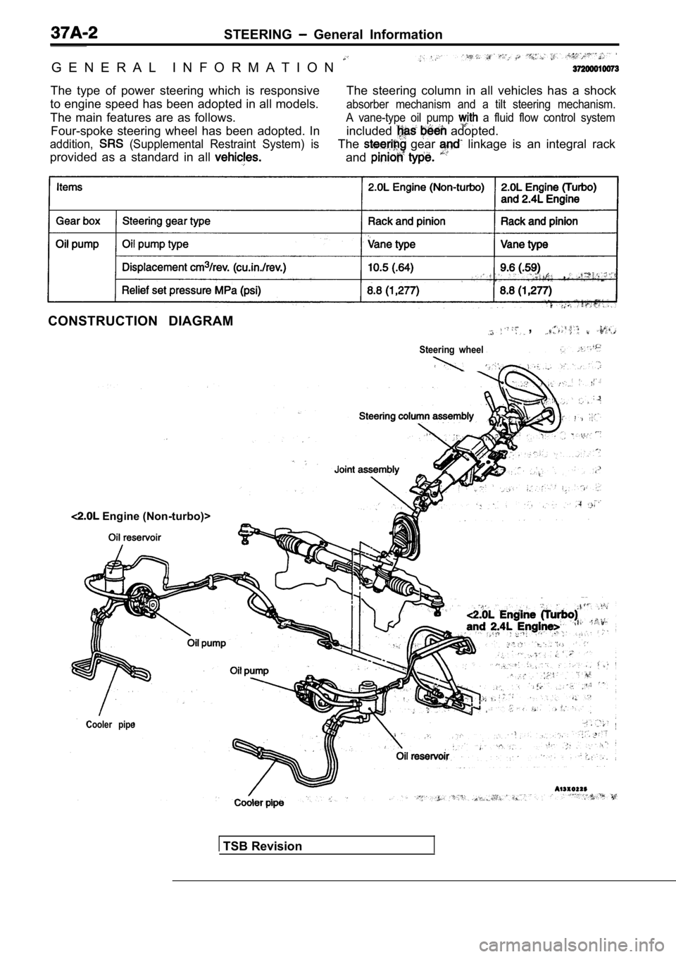
STEERING General Information
G E N E R A L I N F O R M A T I O N
The type of power steering which is responsive
to engine speed has been adopted in all models.
The main features are as follows. The steering column in all vehicles has a shock
absorber mechanism and a tilt steering mechanism.
Four-spoke steering wheel has been adopted. In
A vane-type oil pump a fluid flow control system
addition, (Supplemental Restraint System) is
included adopted.
provided as a standard in all
The gear linkage is an integral rack
and
CONSTRUCTION DIAGRAM,
Steering wheel
Cooler pipe
Engine (Non-turbo)>
TSB Revision