Page 48 of 2103

GENERAL Maintenance
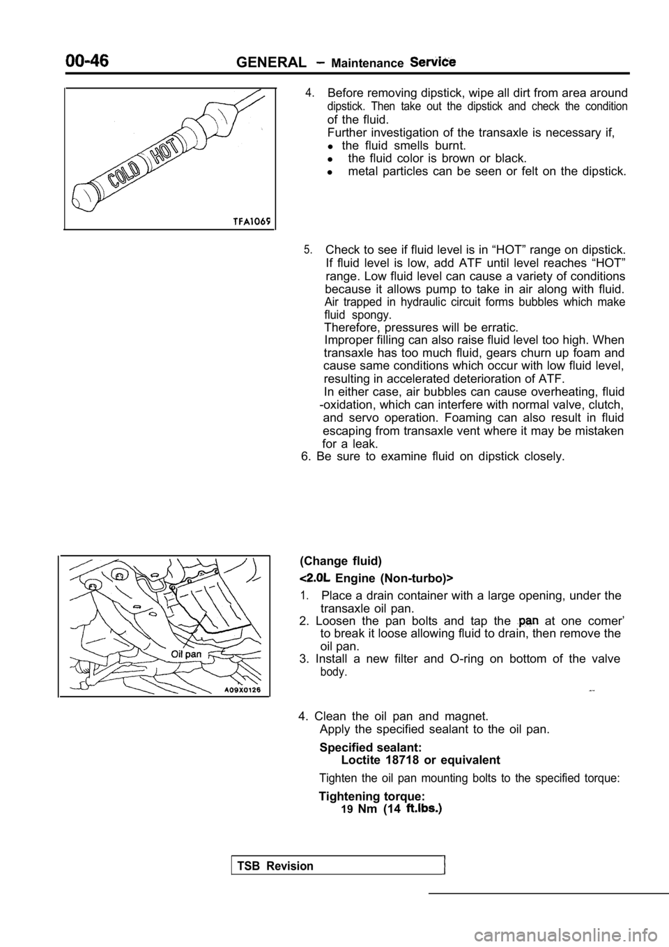
4.Before removing dipstick, wipe all dirt from area around
dipstick. Then take out the dipstick and check the condition
of the fluid.
Further investigation of the transaxle is necessary if,
l the fluid smells burnt.
l the fluid color is brown or black.
l metal particles can be seen or felt on the dipstick .
5.Check to see if fluid level is in “HOT” range on dipstick.
If fluid level is low, add ATF until level reaches “HOT”
range. Low fluid level can cause a variety of condi tions
because it allows pump to take in air along with fl uid.
Air trapped in hydraulic circuit forms bubbles which make
fluid spongy.
Therefore, pressures will be erratic. Improper filling can also raise fluid level too hig h. When
transaxle has too much fluid, gears churn up foam a nd
cause same conditions which occur with low fluid le vel,
resulting in accelerated deterioration of ATF.
In either case, air bubbles can cause overheating, fluid
-oxidation, which can interfere with normal valve, clutch,
and servo operation. Foaming can also result in flu id
escaping from transaxle vent where it may be mistak en
for a leak.
6. Be sure to examine fluid on dipstick closely.
(Change fluid)
Engine (Non-turbo)>
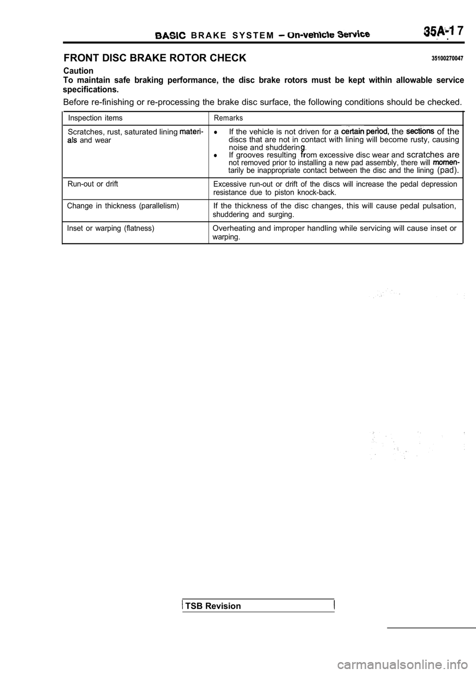
1.Place a drain container with a large opening, under the
transaxle oil pan.
2. Loosen the pan bolts and tap the
at one comer’
to break it loose allowing fluid to drain, then rem ove the
oil pan.
3. Install a new filter and O-ring on bottom of the valve
body.
4. Clean the oil pan and magnet.
Apply the specified sealant to the oil pan.
Specified sealant: Loctite 18718 or equivalent
Tighten the oil pan mounting bolts to the specified torque:
Tightening torque:
19Nm (14
TSB Revision
Page 660 of 2103
Volume air flow sensor
side connector
Intake air temper-
ature sensor
FUEL INJECTION
AND FUEL PUMP RELAY
1.
2.
3.
4.
5.
Remove the relay.
Check the continuity between the
Inspection terminals
2 - 4
Continuity
70
Use the jumper leads to connect relay terminal 4 to
battery terminal and terminal to termi-
nal.
Check the continuity between relay 1 3 while
connecting and disconnecting the
‘at bat-
tery terminal.
Jumper leadContinuity 3
ConnectedContinuity
Disconnected No continuity
If there is a defect, replace
relay.
.
INTAKE AIR TEMPERATURE SENSOR CHECK
13106260676
1.Disconnect the volume air flow, connectors.
2. Measure resistance between
5
Temperature
(32)
20 (66)
60 (176)5.3-6.7
3.Measure resistance while heating the sensor using a hair
drier.
Temperature
Higher
4. If resistance does not decrease as heat the
resistance remains unchanged, replace the volume ai r
flow sensor assembly.
Page 1655 of 2103

B R A K E S Y S T E M 7 .
FRONT DISC BRAKE ROTOR CHECK
35100270047
Caution
To maintain safe braking performance, the disc brak e rotors must be kept within allowable service
specifications.
Before re-finishing or re-processing the brake disc surface, the following conditions should be checke d.
Inspection itemsRemarks
Scratches, rust, saturated lining lIf the vehicle is not driven for a the of the
and weardiscs that are not in contact with lining will beco me rusty, causing
noise and shudderin.lIf grooves resultingrom excessive disc wear and scratches arenot removed prior to installing a new pad assembly, there will tarily be inappropriate contact between the disc and the lining (pad).
Run-out or drift
Excessive run-out or drift of the discs will increa se the pedal depression
resistance due to piston knock-back.
Change in thickness (parallelism)
If the thickness of the disc changes, this will cau se pedal pulsation,
shuddering and surging.
Inset or warping (flatness)
Overheating and improper handling while servicing w ill cause inset or
warping.
TSB Revision