1990 MITSUBISHI SPYDER light
[x] Cancel search: lightPage 7 of 2103

GENERAL How to Use This Manual
1 S T E E R I N G
Power Steering Gear B
O X
POWER STEERING GEAR BOX
6
gear
.
TIE-ROD END
.Operating procedures, etc. on removal, assembly
1. sun tie the cord of the special tool described.
2.Loosen the nut but do not
FOG LIGHT RELAY CHECK
I indicates that there is134 ,continuity’ between the o - - - anals.
supplied indicates terminals‘ to
which battery
S T E E R I N G Power Steering Box
Page 22 of 2103
GENERAL before Service
PRECAUTIONS BEFORE SERVICE.
SUPPLEMENTAL RESTRAINT SYSTEM
1. to follow when servicing SRS
(1) Be sure to read GROUP Supplemental Restraint System
For safe operations, please follow the directions a nd heed all
(2) Always use the designated special tools and tes t equipment.
(3) Wait at least 60 seconds after disconnecting the battery cable before” further work;
The SRS system is designed to retain enough voltage to deploy the air bag even after the battery
has been disconnected. Serious injury may result from unintended air bag deployment if work
is done on the SRS system immediately after the bat tery cable is disconnected.
(4) Never attempt to disassemble or repair the SRS components (SRS-ECU air bag module and
clock spring). If faulty, replace it.
(5) Warning labels must be heeded when servicing or handling SRS components. Warning labels
are located in the following locations.
Sun visor
l Glove box
. S R S - E C U
l Steering wheel
l Air bag module
l Clock spring
l Steering gear and linkage clamp
(6) Store components removed from the SRS
a clean and dry place.
The air bag module should be stored on a flat surfa ce and placed so that the pad surface is’
facing upward.
Do not place anything on top of it.
(7) Be sure to deploy the air bag before disposing of the air bag’module or disposing of a vehicle
equipped with an air bag. (Refer to GROUP
Air Bag Module Disposal Procedures.)
(8) Whenever you finish servicing the
check the SRS warning light operation to make sure
that the system functions properly.
2.Observe the following when carrying out operations on places where SRS components are installed,’
.,
including operations not directly related to the SR S air bag.
(1) When removing or installing parts do not allow any impact or shock to the SRS components.
(2) SRS components should not be subjected to heat over so remove the SRS compo-
nents before drying or baking the vehicle after painting.
After re-installing them, check the SRS warning lig ht operation to make sure that the system
functions properly.
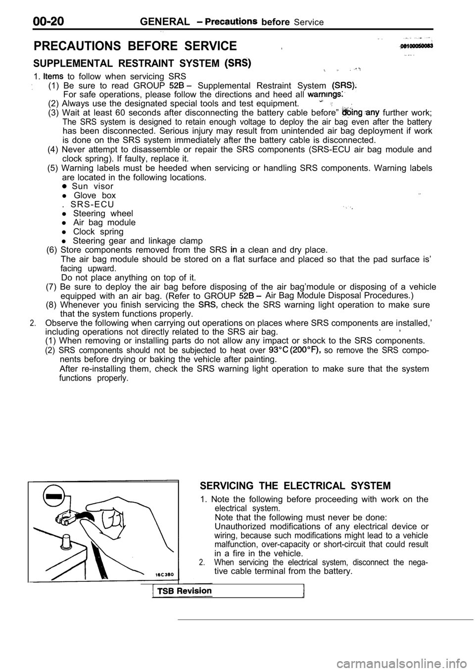
SERVICING THE ELECTRICAL SYSTEM
1. Note the following before proceeding with work o n the
electrical system.
Note that the following must never be done:
Unauthorized modifications of any electrical device or
wiring, because such modifications might lead to a vehicle
malfunction, over-capacity or short-circuit that co uld result
in a fire in the vehicle.
2.When servicing the electrical system, disconnect th e nega-
tive cable terminal from the battery.
Page 23 of 2103
GENERAL Precautions before Service . .
Caution
1.Before connecting or disconnecting the negative
be sure to turn off the ignition and
the lighting switch.
(if this is not done, the possibility semi-
conductor parts being damaged.)
2.After completion of the work steps [when the bat-
tery’s negative terminal is connected], warm
up the engine and allow it for approximately
five minutes under the conditions be-
low, in order to stabilize the engine condi-
tions, and then check to be sure that idling’ is
satisfactory.
Engine temperature:
Lights, electric fans, accessories: OFF
Transaxle: Neutral position
(A/T models: “N” or “P”)
Steering
neutral (center) position
mm (in.)
Scan tool
ROM pack
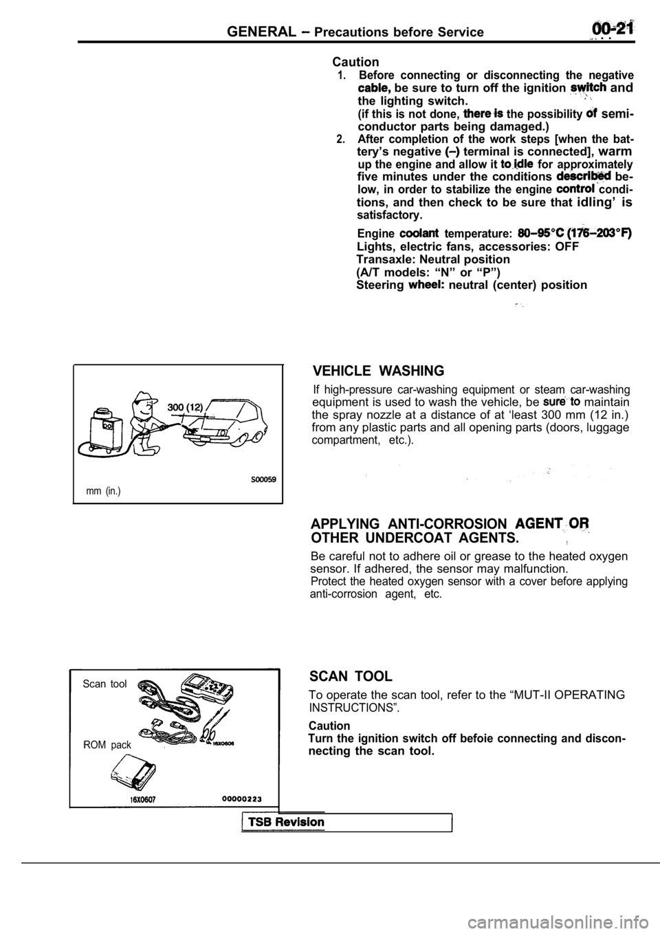
VEHICLE WASHING
If high-pressure car-washing equipment or steam car -washing
equipment is used to wash the vehicle, be maintain
the spray nozzle at a distance of at ‘least 300 mm (12 in.)
from any plastic parts and all opening parts (doors , luggage
compartment, etc.).
APPLYING ANTI-CORROSION
OTHER UNDERCOAT AGENTS.,
Be careful not to adhere oil or grease to the heate d oxygen
sensor. If adhered, the sensor may malfunction.
Protect the heated oxygen sensor with a cover befor e applying
anti-corrosion agent, etc.
SCAN TOOL
To operate the scan tool, refer to the “MUT-II OPER ATING
INSTRUCTIONS”.
Caution
Turn the ignition switch off befoie connecting and discon-
necting the scan tool.
Page 52 of 2103

GENERAL Maintenance Service
2.Check the wheel cylinder boots for evidence, a’ brake
fluid leak. Visually check the
boots for tears or
cracks. (A slight amount of fluid on the boot may not
be a leak, but may be preservative assembly.)
Caution
The shoes for the right and left be,
replaced at the same time.
Never split or intermix brake
sets.
All four shoes must be replaced as a set.
Thickness of lining
Limit: 1.0 mm in.)
17. BRAKE HOSES (Check for
leaks)
Check of brake hoses and tubing should be
brake service operations.
The hoses should be checked for:
1.Correct length, severe surface cracking, pulling, scuffing
or worn spots. (If the fabric casing of the hoses i s exposed
by cracks of abrasion in the rubber hose cover, the hoses
should be replaced. Eventual deterioration of may
occur with possible bursting failure.)
2. Faulty installation, casing twisting or interfer ence
wheel,’ tire or chassis.
18. BALL JOINT AND STEERING SEALS
(Check for grease leaks damage)
1. These components, which are permanently lubricat ed
at the factory, do not require periodic lubrication. Damaged
seals and boots should be replaced to prevent leakage
or contamination of the grease.
2.Check the dust cover and boots for proper sealing, leakage
and damage. Replace them if defective.
19. DRIVE SHAFT BOOTS (Check for leaks
and damage)
1. These components, which are permanently lubricat ed
at the factory, do not require periodic Damaged
boots should be replaced to prevent leakage or contamina-
tion of the grease.
2.Check the boots for proper sealing, leakage and damage.
Replace it if defective.
AXLE OIL (Check oil level)-AWD
Remove the filler plug and check the oil level at bottom of
filler hole. If the oil level is slightly below the filler hole, it
is in satisfactory condition.
Page 53 of 2103
GENERAL Maintenance
21 SYSTEM component
damage, to wiring,
harness, etc.)
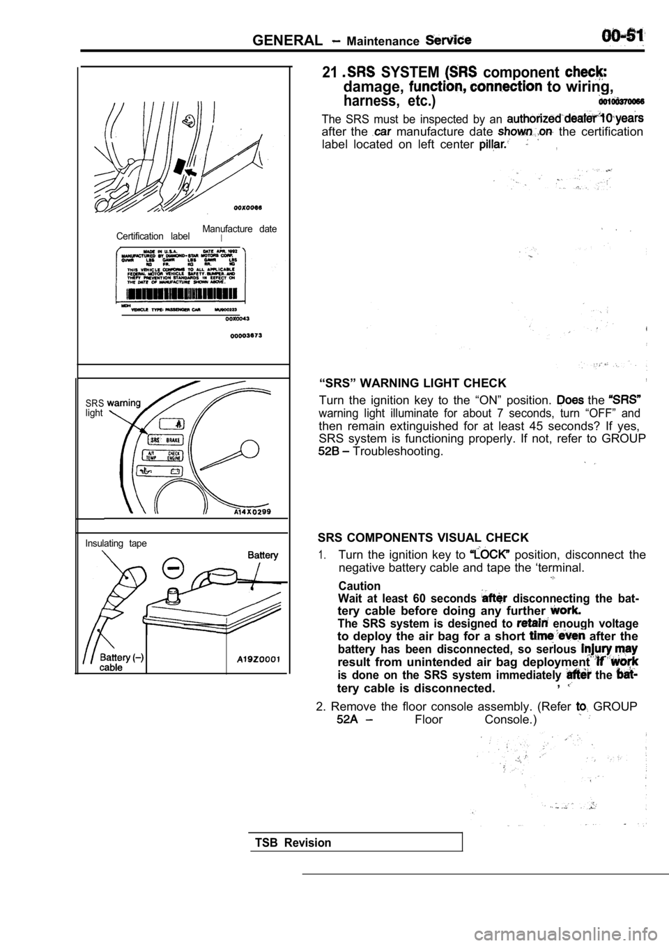
Certification labelManufacture dateI
SRSlight
Insulating tape
The SRS must be inspected by an
after the manufacture date the certification
label located on left center
,
“SRS” WARNING LIGHT CHECK,
Turn the ignition key to the “ON” position. the
warning light illuminate for about 7 seconds, turn “OFF” and
then remain extinguished for at least 45 seconds? I f yes,
SRS system is functioning properly. If not, refer t o GROUP
Troubleshooting.
SRS COMPONENTS VISUAL CHECK
1.Turn the ignition key to position, disconnect the
negative battery cable and tape the ‘terminal.
Caution
Wait at least 60 seconds
disconnecting the bat-
tery cable before doing any further
The SRS system is designed to enough voltage
to deploy the air bag for a short after the
battery has been disconnected, so serlous
result from unintended air bag deployment
is done on the SRS system immediately the
tery cable is disconnected. ,
2. Remove the floor console assembly. (Refer GROUP
Floor Console.)
TSB Revision
Page 57 of 2103
GENERAL Main and Adhesive Table
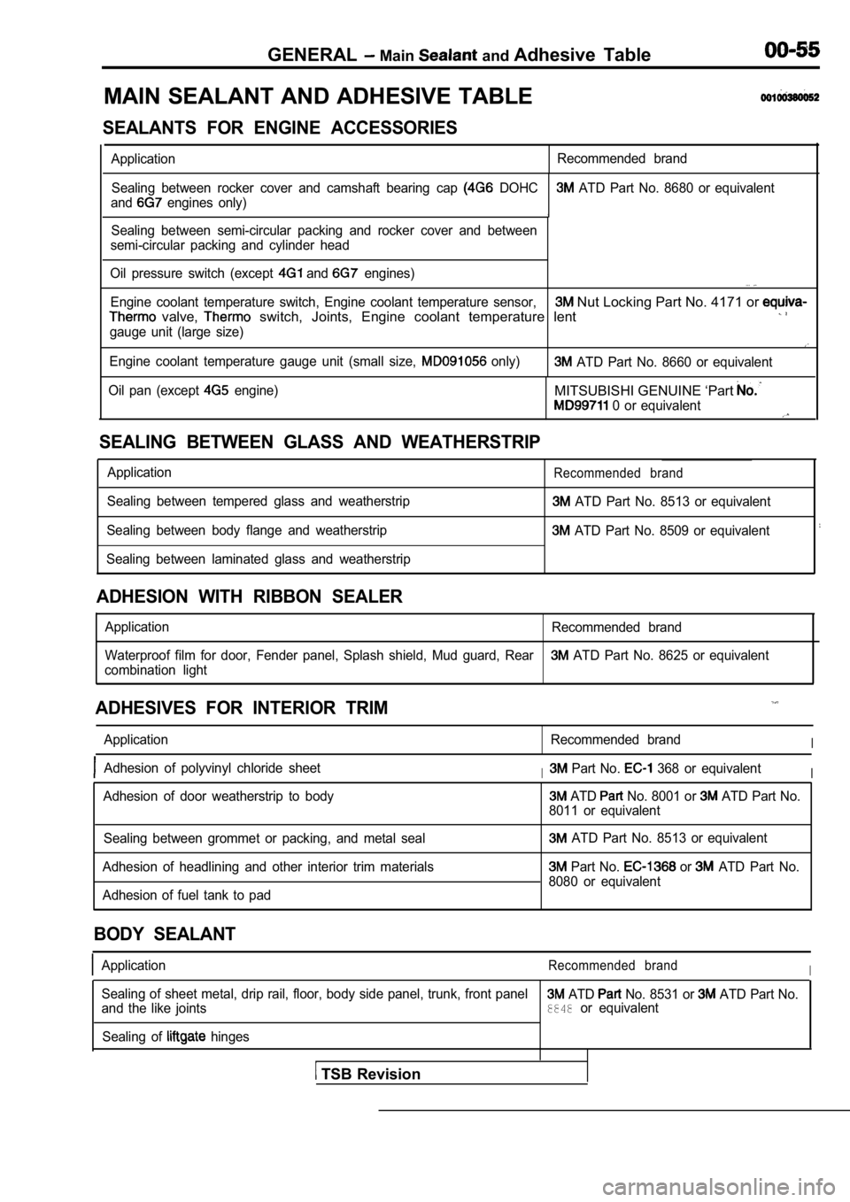
MAIN SEALANT AND ADHESIVE TABLE
SEALANTS FOR ENGINE ACCESSORIES
Application Recommended brand
Sealing between rocker cover and camshaft bearing c ap
DOHC ATD Part No. 8680 or equivalent
and
engines only)
1Sealing between semi-circular packing and rocker co ver and between
semi-circular packing and cylinder head
Oil pressure switch (except
and engines). . .
Engine coolant temperature switch, Engine coolant t emperature sensor, Nut Locking Part No. 4171 or
valve, switch, Joints, Engine coolant temperature lent
gauge unit (large size)
Engine coolant temperature gauge unit (small size, only) ATD Part No. 8660 or equivalent
Oil pan (except
engine)MITSUBISHI GENUINE ‘Part
0 or equivalent
SEALING BETWEEN GLASS AND WEATHERSTRIP
Application
Sealing between tempered glass and weatherstrip
Sealing between body flange and weatherstrip
Sealing between laminated glass and weatherstripRecommended brand
ATD Part No. 8513 or equivalent
ATD Part No. 8509 or equivalent
ADHESION WITH RIBBON SEALER
Application Recommended brand
Waterproof film for door, Fender panel, Splash shie ld, Mud guard, Rear
ATD Part No. 8625 or equivalent
combination light
ADHESIVES FOR INTERIOR TRIM
Application Recommended brandI
Adhesion of polyvinyl chloride sheetI Part No. 368 or equivalentI
Adhesion of door weatherstrip to body ATD No. 8001 or ATD Part No.
8011 or equivalent
Sealing between grommet or packing, and metal seal
Adhesion of headlining and other interior trim mate rials
Adhesion of fuel tank to pad
ATD Part No. 8513 or equivalent
Part No. or ATD Part No.
8080 or equivalent
BODY SEALANT
ApplicationRecommended brandI
Sealing of sheet metal, drip rail, floor, body side panel, trunk, front panel ATD No. 8531 or ATD Part No.
and the like joints8848or equivalent
Sealing of
hinges
TSB Revision
Page 69 of 2103
ENGINE On-vehicle
A/C COMPRESSOR DRIVE BELT TENSION ADJUSTMENT
1. Loosen tension pulley fixing bolt A.
2. Adjust belt tension with adjusting bolt B.
Standard value:
Items
Tension
(Ibs.)
Deflection
When a new belt isWhen a used belt is
installedinstalled
382-411255-333
6.5-7.5
3. Tighten fixing nut A.
Tightening torque: 23-26 Nm
4.Check the belt deflection and readjust if neces-
sary.
Caution
This check should be carried out after turning the
crankshaft one full rotation or more in the forward
direction (to the right).
IGNITION TIMING CHECK
1.Before inspection and adjustment set vehicle in the follow-
ing condition.
lEngine coolant temperature:
lLights, electric cooling fan and all accessories: OFF
lTransaxle: Neutral (P range on vehicles with
2. Turn the ignition switch to OFF and connect the scan
tool to the data link connector.
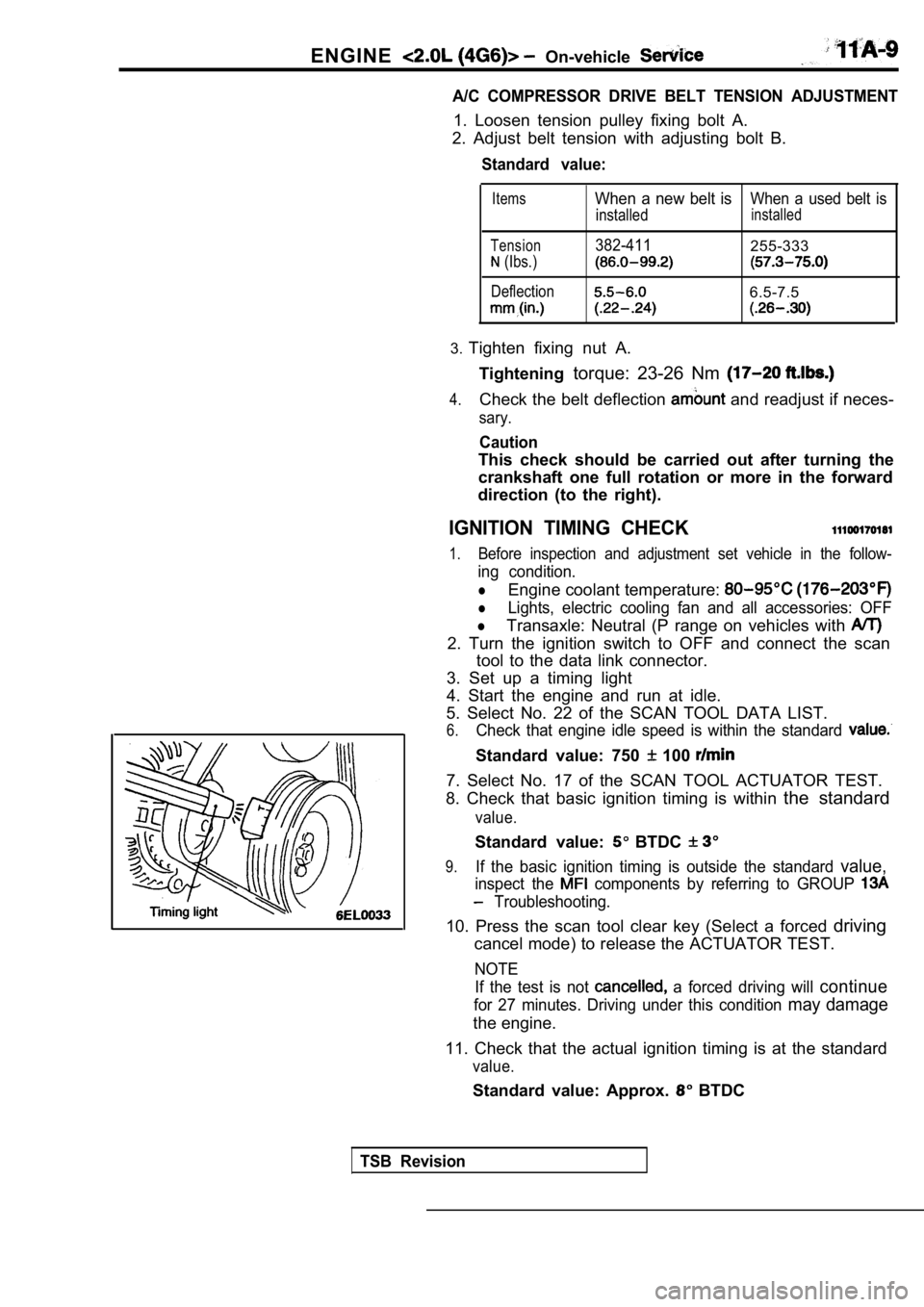
3. Set up a timing light
4. Start the engine and run at idle.
5. Select No. 22 of the SCAN TOOL DATA LIST.
6.Check that engine idle speed is within the standard
Standard value: 750 100
7. Select No. 17 of the SCAN TOOL ACTUATOR TEST.
8. Check that basic ignition timing is within the standard
value.
Standard value: BTDC
9.If the basic ignition timing is outside the standar d value,
inspect the components by referring to GROUP
Troubleshooting.
10. Press the scan tool clear key (Select a forced driving
cancel mode) to release the ACTUATOR TEST.
NOTE
If the test is not
a forced driving will continue
for 27 minutes. Driving under this condition may damage
the engine.
11. Check that the actual ignition timing is at the standard
value.
Standard value: Approx. BTDC
TSB Revision
Page 70 of 2103
ENGINE On-vehicle Service
NOTE
1.Ignition timing is variable within about even under
operating.
2. And it is automatically further advanced by abou t
from BTDC at higher altitudes.
CURB IDLE SPEED CHECK
1. Before inspection and adjustment, set vehicles in the
following condition.
lEngine coolant temperature:
lLights, electric cooling fan and all accessories: OFF
lTransaxle: Neutral (P range on vehicles with
2. Turn the ignition switch to OFF and connect the scan
tool to the data link connector.
3. Select No. 17 of the SCAN TOOL ACTUATOR TEST.
4. Check the basic ignition timing.
Standard
BTDC
5. Run the engine at idle for 2 minutes.
6. Select No. 22 of the SCAN TOOL DATA LIST.
7. Check the curb idle speed.
Standard value: 750
100
NOTE
The idle speed is controlled automatically by the i dle air
control system.
8. If the idle speed is outside the standard value, inspect
the components by referring to GROUP Trou-
bleshooting.
IDLE MIXTURE CHECK .
1.Before inspection, set in following
lEngine coolant temperature:
lLights, electric cooling fan all
lTransaxle: Neutral (P range on
2. Turn the ignition switch to OFF and, connect the scan
tool to the data link ,
3. Select No. 17 of the SCAN TOOL
4.Check that the basic ignition
value.
Standard value: BTDC
5. Run the engine 2,500 for 2 minutes.
6. Set the CO, HC tester.
7. Check the CO contents and the HC contents, at id le.
Standard value: CO contents: 0.5% or less
HC contents: 100 rpm or less
Revision