1990 MITSUBISHI SPYDER light
[x] Cancel search: lightPage 305 of 2103
E N G I N E Timing Belt
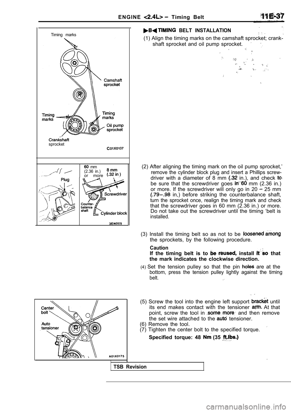
Timing marks
sprocket
mm
(2.36 in.)
or more .
BELT INSTALLATION
(1) Align the timing marks on the camshaft sprocket ; crank-
shaft sprocket and oil pump sprocket.
,
. . .
(2) After aligning the timing mark on the oil pump sprocket,’
remove the cylinder block plug and insert a Phillips screw-
driver with a diameter of 8 mm in.), and check
be sure that the screwdriver goes mm (2.36 in.)
or more. If the screwdriver will only go in 20
25 mm
in,) before striking the counterbalance shaft,
turn the sprocket once, realign the timing mark and check
that the screwdriver goes in 60 mm (2.36 in.) or mo re.
Do not take out the screwdriver until the timing ‘b elt is
installed.
(3) Install the timing belt so as not to be
the sprockets, by the following procedure.
Caution
If the timing belt is to install that
the mark indicates the clockwise direction.
(4) Set the tension pulley so that the pin
are at the
bottom, press the tension pulley lightly against th e timing
belt.
TSB Revision
(5) Screw the tool into the engine left support until
its end makes contact with the tensioner
At that
point, screw the tool in
and then remove
the set wire attached to the
tensioner.
(6) Remove the tool.
(7) Tighten the center bolt to the specified torque .
Specified torque: 48 (35
Page 340 of 2103
ENGINE OVERHAUL Rocker Arms and Camshaft
R E M O V A L S E R V I C E
ARMS AND ARM
REMOVAL.
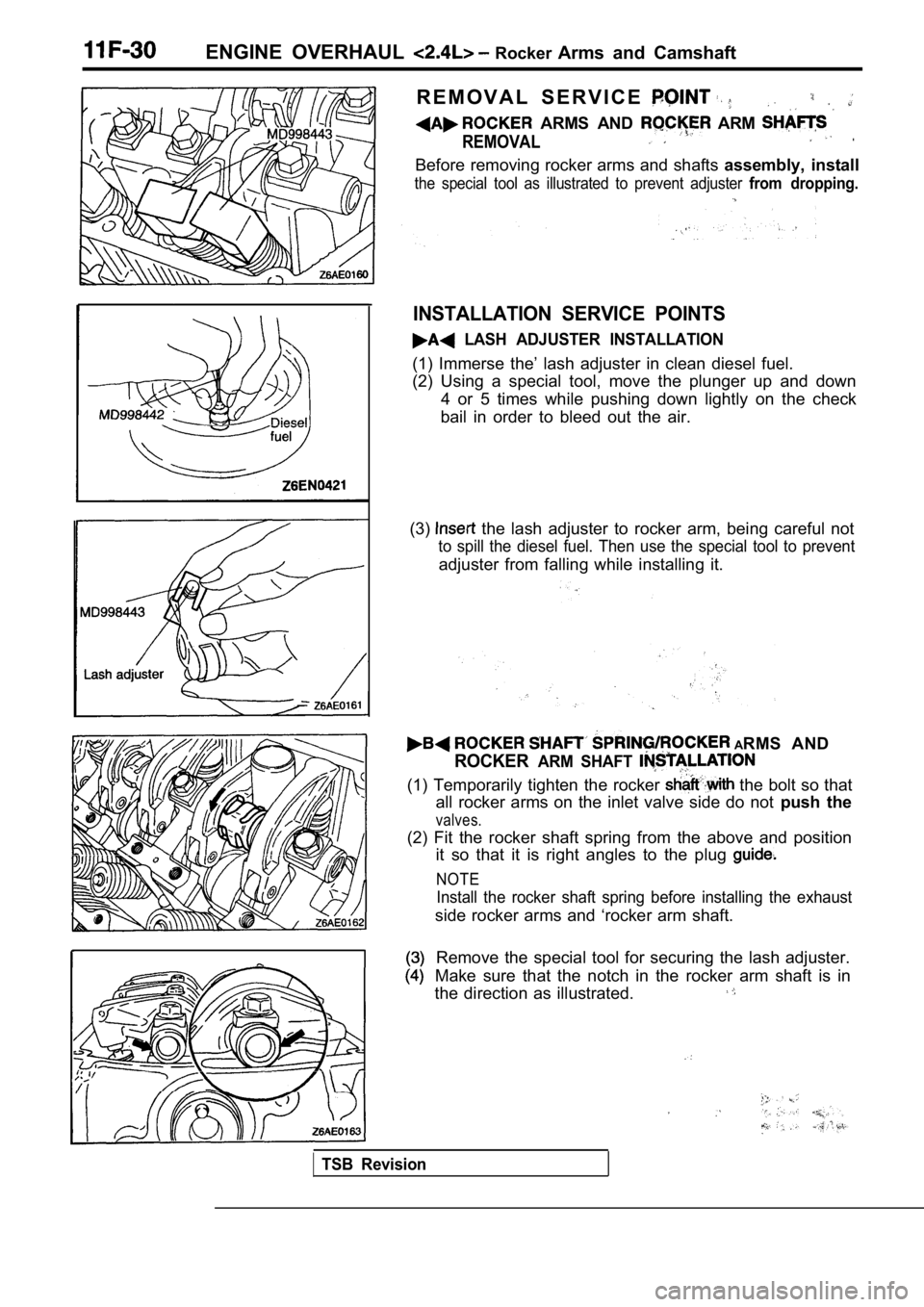
Before removing rocker arms and shafts assembly, install
the special tool as illustrated to prevent adjuster from dropping.
INSTALLATION SERVICE POINTS
LASH ADJUSTER INSTALLATION
(1) Immerse the’ lash adjuster in clean diesel fuel .
(2) Using a special tool, move the plunger up and d own
4 or 5 times while pushing down lightly on the chec k
bail in order to bleed out the air.
(3)
the lash adjuster to rocker arm, being careful not
to spill the diesel fuel. Then use the special tool to prevent
adjuster from falling while installing it.
ARMS AND
ROCKERARM SHAFT
(1) Temporarily tighten the rocker the bolt so that
all rocker arms on the inlet valve side do not push the
valves.
(2) Fit the rocker shaft spring from the above and position
it so that it is right angles to the plug
NOTE
Install the rocker shaft spring before installing t he exhaust
side rocker arms and ‘rocker arm shaft.
Remove the special tool for securing the lash adjus ter.
Make sure that the notch in the rocker arm shaft is in
the direction as illustrated.
TSB Revision
Page 342 of 2103
ENGINE OVERHAUL Rocker Arms Camshaft
I
INSPECTION
CAMSHAFT.
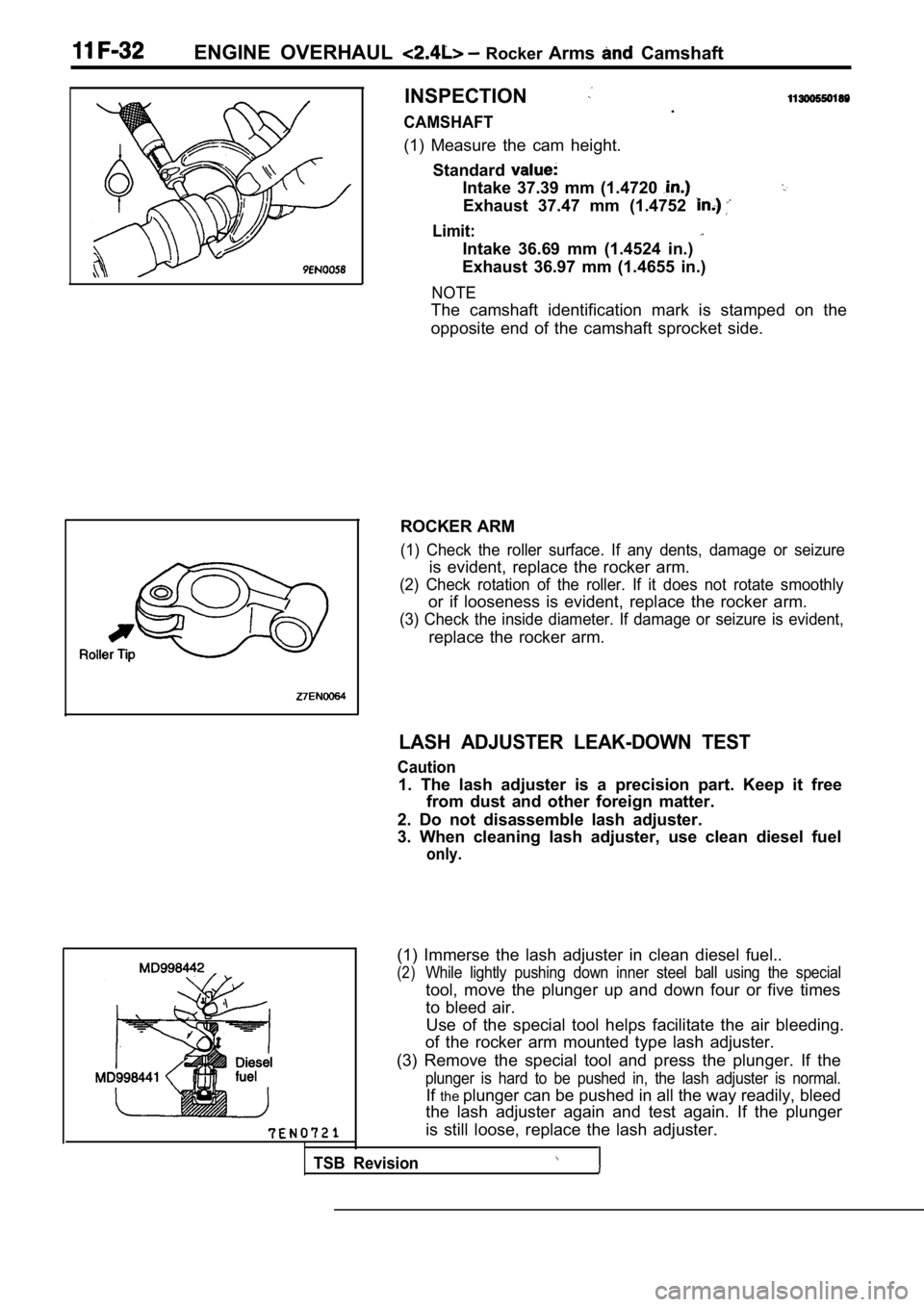
(1) Measure the cam height. Standard
Intake 37.39 mm (1.4720
Exhaust 37.47 mm (1.4752
Limit:
Intake 36.69 mm (1.4524 in.)
Exhaust 36.97 mm (1.4655 in.)
NOTE
The camshaft identification mark is stamped on the
opposite end of the camshaft sprocket side.
ROCKER ARM
(1) Check the roller surface. If any dents, damage or seizure
is evident, replace the rocker arm.
(2) Check rotation of the roller. If it does not rotate smoothly
or if looseness is evident, replace the rocker arm.
(3) Check the inside diameter. If damage or seizure is evident,
replace the rocker arm.
LASH ADJUSTER LEAK-DOWN TEST
Caution
1. The lash adjuster is a precision part. Keep it f ree
from dust and other foreign matter.
2. Do not disassemble lash adjuster.
3. When cleaning lash adjuster, use clean diesel fu el
only.
Use of the special tool helps facilitate the air bleeding.
of the rocker arm mounted type lash adjuster.
(3) Remove the special tool and press the plunger. If the
plunger is hard to be pushed in, the lash adjuster is normal.
Ifthe plunger can be pushed in all the way readily, bleed
the lash adjuster again and test again. If the plun ger
is still loose, replace the lash adjuster.
TSB Revision
(1) Immerse the lash adjuster in clean diesel fuel. .
(2)While lightly pushing down inner steel ball using t he special
tool, move the plunger up and down four or five tim es
to bleed air.
Page 385 of 2103
ENGINE (NON-TURBO)>
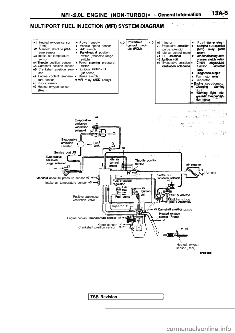
MULTIPORT FUEL INJECTION SYSTEM
Heated oxygen sensor Power supply(Front)l Vehicle speed sensor
Manifold absolute l switch
sure sensor l position Intake air temperature
switch (transaxle rangesensor switch) position sensor Power pressure Camshaft position sensor Crankshaft position sen- l ignitionsor sense) Engine coolant tempera- l Brake switch
ture sensor relay r e l a y ) Knock sensor Heated oxygen sensor(Rear)
Injector l
F u e l Evaporative l fuel purge solenoid Idle air control motor EET
“Evaporative emission l
.l Fan motor l Generator speedometer
light
.
Fuel
canister
absolute pressure sensor
Intake air temperature sensor
Positive crankcase
ventilation valve
I n j e c t o r
transducer
sensor
Engine coolant
Knock sensor
Crankshaft position sensor
Air inlet
Heated oxygen
sensor (Rear)
Revision
Page 391 of 2103
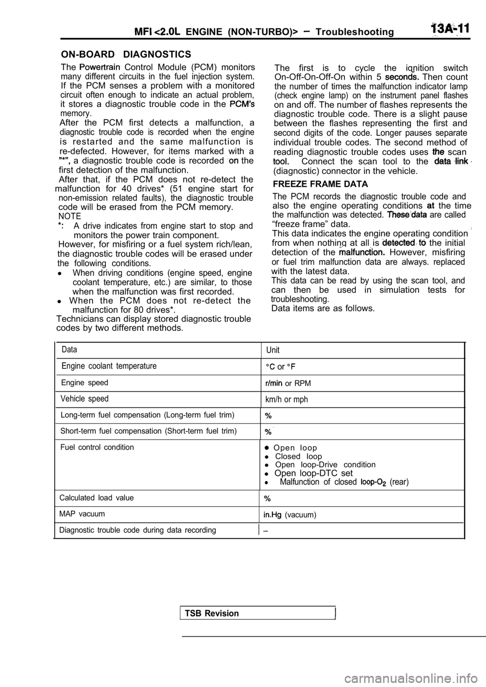
ON-BOARD DIAGNOSTICS
The
Control Module (PCM) monitors
many different circuits in the fuel injection syste m.
If the PCM senses a problem with a monitored
circuit often enough to indicate an actual problem,
it stores a diagnostic trouble code in the
memory.
After the PCM first detects a malfunction, a
diagnostic trouble code is recorded when the engine
i s r e s t a r t e d a n d t h e s a m e m a l f u n c t i o n i s
re-defected. However, for items marked with a
a diagnostic trouble code is recorded the
first detection of the malfunction.
After that, if the PCM does not re-detect the
malfunction for 40 drives* (51 engine start for
non-emission related faults), the diagnostic troubl e
code will be erased from the PCM memory.
NOTE
A drive indicates from engine start to stop and
monitors the power train component.
However, for misfiring or a fuel system rich/lean,
the diagnostic trouble codes will be erased under
the following conditions.
lWhen driving conditions (engine speed, engine
coolant temperature, etc.) are similar, to those
when the malfunction was first recorded.
l When the PCM does not re-detect the
malfunction for 80 drives*.
Technicians can display stored diagnostic trouble
codes by two different methods.
ENGINE (NON-TURBO)> Troubleshooting
The first is to cycle the ignition switch
On-Off-On-Off-On within 5
Then count
the number of times the malfunction indicator lamp
(check engine lamp) on the instrument panel flashes
on and off. The number of flashes represents the
diagnostic trouble code. There is a slight pause
between the flashes representing the first and
second digits of the code. Longer pauses separate
individual trouble codes. The second method of
reading diagnostic trouble codes uses
scan
Connect the scan tool to the
(diagnostic) connector in the vehicle.
FREEZE FRAME DATA
The PCM records the diagnostic trouble code and
also the engine operating conditions the time
the malfunction was detected. are called
“freeze frame” data.
This data indicates the engine operating condition
from when nothing at all is the initial
detection of the
However, misfiring
or fuel trim malfunction data are always. replaced
with the latest data.
This data can be read by using the scan tool, and
can then be used in simulation tests for
troubleshooting.
Data items are as follows.
DataUnit
Engine coolant temperature
Engine speed
Vehicle speed
or
or RPM
km/h or mph
Long-term fuel compensation (Long-term fuel trim)
Short-term fuel compensation (Short-term fuel trim)
Fuel control condition O p e n l o o p
l Closed loop
l Open loop-Drive condition
l Open loop-DTC set
lMalfunction of closed (rear)
Calculated load value
MAP vacuum
(vacuum)
Diagnostic trouble code during data recording
TSB Revision
Page 393 of 2103
ENGINE (NON-TURBO)> Troubleshooting 3
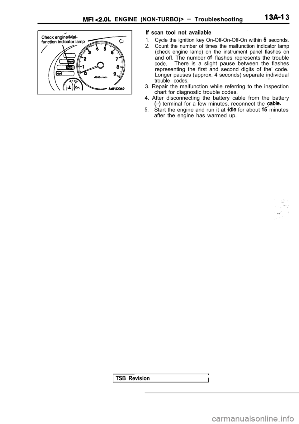
If scan tool not available
1.Cycle the ignition key On-Off-On-Off-On within seconds.
2.Count the number of times the malfunction indicator lamp
(check engine lamp) on the instrument panel flashes on
and off. The number flashes represents the trouble
code.There is a slight pause between the flashes
representing the first and second digits of the’ co de.
Longer pauses (approx. 4 seconds) separate individu al
,
trouble codes.
3. Repair the malfunction while referring to the in spection
chart for diagnostic trouble codes.
4. After disconnecting the battery cable from the b attery
terminal for a few minutes, reconnect the
5.Start the engine and run it at for about minutes
after the engine has warmed up.
TSB RevisionI
Page 405 of 2103
![MITSUBISHI SPYDER 1990 Service Repair Manual ENGINE (NON-TURBO)>
C h a r g i n g T o o
47
[Comment]
Background
The PCM tries to maintain charging system voltage of between and 15 volts.
l This code indicates:
The batte MITSUBISHI SPYDER 1990 Service Repair Manual ENGINE (NON-TURBO)>
C h a r g i n g T o o
47
[Comment]
Background
The PCM tries to maintain charging system voltage of between and 15 volts.
l This code indicates:
The batte](/manual-img/19/57345/w960_57345-404.png)
ENGINE (NON-TURBO)>
C h a r g i n g T o o
47
[Comment]
Background
The PCM tries to maintain charging system voltage of between and 15 volts.
l This code indicates:
The battery voltage input is below the target charg ing voltage during engine
andNo significant change in voltage has been detected during active testing of the generator
output circuit.
Range of Check
lEngine speed: or more for approx. one minutelBattery positive voltage is at least 1 lower than the target charging voltage for approx.60 seconds.Set ConditionlBattery positive voltage does not change even if th e generator field current is cut off.
lDefects in generator or adjustmentl High resistance generatorl High between battery and
generator ground
l PCM
Check that the generator drive belt is properly in stalled. Repair
NG Measure the voltage between the generator terminal and the battery positive terminal. Engine: 1600 Headlight: High beam ON)
OK: Less than
Check the harness wire and terminal generator terminal and battery necessary.
NGMeasure the voltage between the generator body and battery Check the generator grounded line: neoative terminal. Engine: 1600 Headlight: High beam ON)
OK: Less than 0.5
OK
Measure at the generator lDisconnect the connector, and measure at the harnes s side.
SCAN TOOL Actuator test 10
relay (ASD relay) isturnedonandoff everyapprox. l Voltage between 1 and ground
[Measure when the relay (ASD relay) is turned on.]
OK: Battery positive voltage
NG Check the wire between generator relay
(ASD relay) connector. Repair, if necessary.
OK
Check the harness wire NG Repair connector.I
OK NG
SCAN TOOL SENSOR READ TEST (Data list) Check the harness wire between the PCM and the bat tery 10 Battery voltage as the ignition switch. Repair, if necessary.OK: indicated on the scan tool and actual positive
Check trouble symptom.
TSB RevisionI
Page 460 of 2103
![MITSUBISHI SPYDER 1990 Service Repair Manual ENGINE (NON-TURBO)>
Scan tool 160
Code General scan tool EVAP Leak Monitor
No.Detected
31
[Comment]
Background
l The PCM monitors that the fuel tank, purge lines, e tc. are MITSUBISHI SPYDER 1990 Service Repair Manual ENGINE (NON-TURBO)>
Scan tool 160
Code General scan tool EVAP Leak Monitor
No.Detected
31
[Comment]
Background
l The PCM monitors that the fuel tank, purge lines, e tc. are](/manual-img/19/57345/w960_57345-459.png)
ENGINE (NON-TURBO)>
Scan tool 160
Code General scan tool EVAP Leak Monitor
No.Detected
31
[Comment]
Background
l The PCM monitors that the fuel tank, purge lines, e tc. are well.
l
ventilation solenoid with the canister ventilation valve (incorporated in the lIf the fuel tank and purge lines are sealed the pressure will rise well by the solenoid specific timeslAfter the pressure rises well, the diaphragm inside the solenoid will not work any more.lIf the purge air leaks slightly, the solenoid will be activated more than specific times.
Range of Check, Set Condition
l The solenoid has been activated more than specific times.
‘ P r o b a b l e
I,
l Fuel tank cap screwed on l tank and purge lines, l Evaporative emission failed
l
l PCM failed’
NGCheck the evaporative Replace
(Refer to GROUP Emission Control System.)
OK
Check the evaporative emission purge solenoid.NG Replace
(Refer to GROUP 17 Emission Control System.)
OK
Check the fuel tank and purge line for leakage.
Scan tool 161
Code General scan tool EVAP Leak Monitor Large Leak
No. Detected
TSB Revision
[Comment]
l The PCM monitors that the fuel tank, purge lines, e tc. are well.
l
ventilation with the canister ventilation valve (incorporated in the solenoid) lIf the fuel tank and purge lines are sealed correct ly, the pressure will well by the solenoid specific times.lAfter the pressure rises well, the diaphragm inside the solenoid will not work any more.lIf the purge air leaks excessively, the solenoid should be activated much more than specific
times.
of Check. Set Condition
l been activated much more than specific times.
Probable cause
l Fuel tank filler cap screwed on lFuel tank and purge seated
l Evaporative solenoid
failed
l
l PCM ,
Check the evaporative emission ventilation solenoid .
(Refer to GROUP 17 Emission Control System.) Replace
NGCheck the evaporative emission purge solenoid. Replace
(Refer to GROUP 17 Emission Control System.)
OK
Check the fuel tank and line for I