1990 MITSUBISHI SPYDER air conditioning
[x] Cancel search: air conditioningPage 77 of 2103
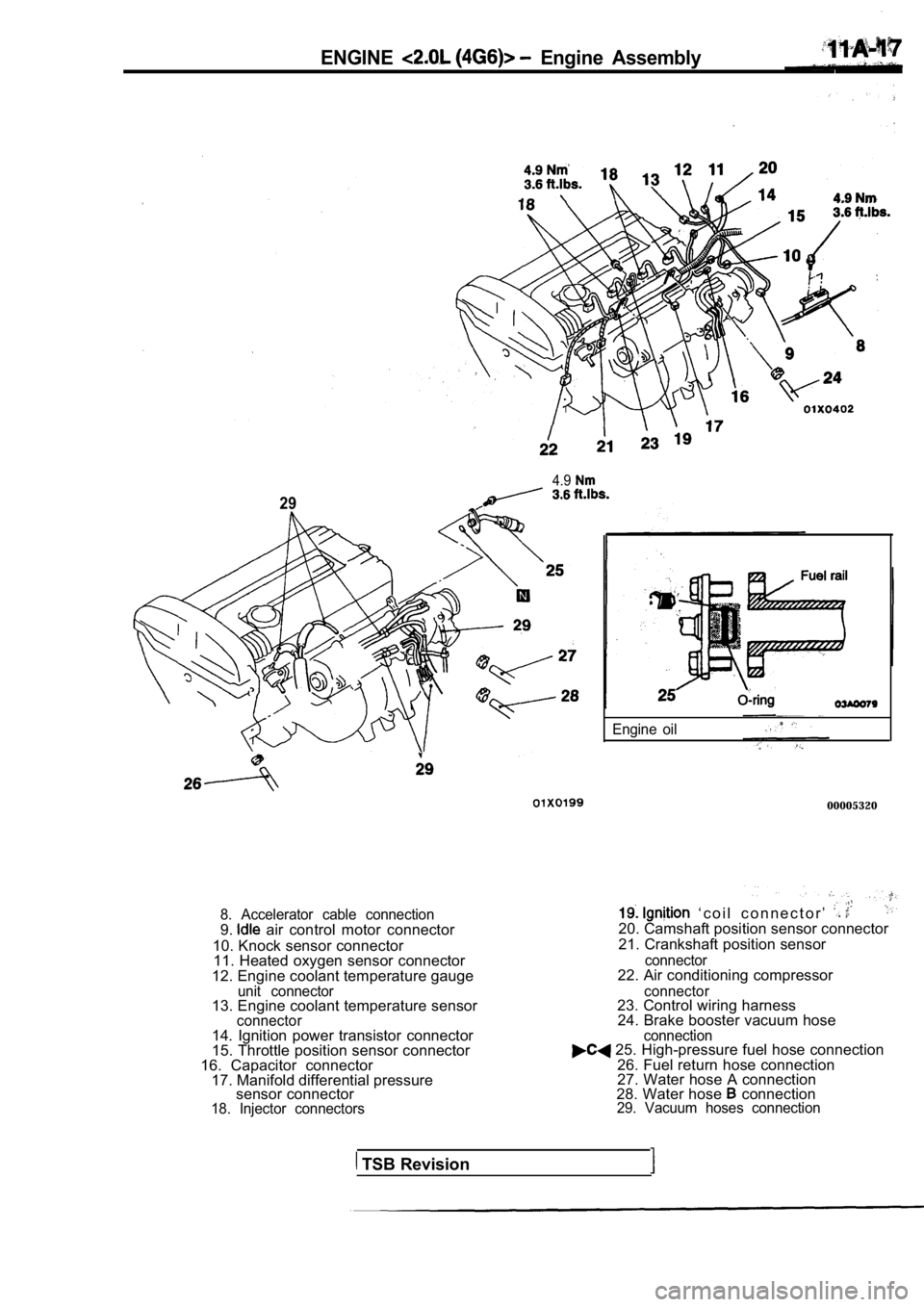
ENGINE Engine Assembly
4.9
29
8. Accelerator cable connection9. air control motor connector
10. Knock sensor connector 11. Heated oxygen sensor connector
12. Engine coolant temperature gauge
unit connector13. Engine coolant temperature sensorconnector
Engine oil
00005320
‘ c o i l c o n n e c t o r ’ 20. Camshaft position sensor connector
21. Crankshaft position sensor
connector22. Air conditioning compressor
connector23. Control wiring harness 24. Brake booster vacuum hose .
14. Ignition power transistor connector
15. Throttle position sensor connector
16. Capacitor connector 17. Manifold differential pressure sensor connector
18. Injector connectors connection
25. High-pressure fuel hose connection
26. Fuel return hose connection
27. Water hose A connection
28. Water hose
connection29. Vacuum hoses connection
TSB Revision
Page 91 of 2103
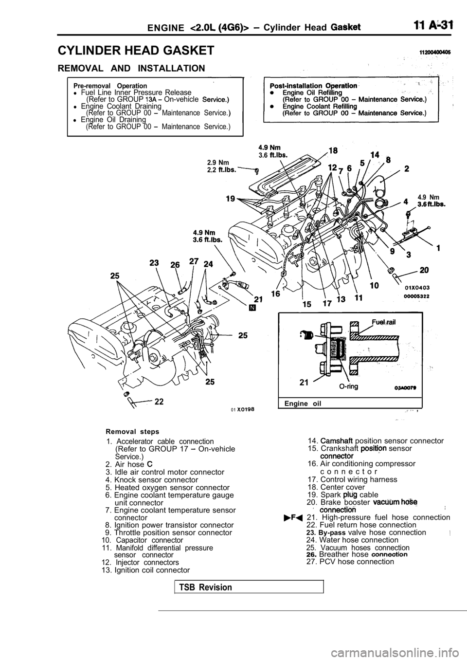
ENGINE Cylinder Head
CYLINDER HEAD GASKET
REMOVAL AND INSTALLATION
Pre-removal Operationl Fuel Line Inner Pressure Release(Refer to GROUP On-vehiclel Engine Coolant Draining(Refer to GROUP 00 Maintenance Service.)l Engine Oil Draining(Refer to GROUP 00 Maintenance Service.)
3.62.9 Nm
2.2
4.9 Nm
220 1
Removal steps
1. Accelerator cable connection(Refer to GROUP 17 On-vehicleService.)2. Air hose 3. Idle air control motor connector
4. Knock sensor connector
5. Heated oxygen sensor connector
6. Engine coolant temperature gauge
unit connector
7. Engine coolant temperature sensor
connector8. Ignition power transistor connector
9. Throttle position sensor connector
10. Capacitor connector
11. Manifold differential pressure sensor connector
12. Injector connectors
13. Ignition coil connector Engine oil
,
21
14. position sensor connector
15. Crankshaft sensor
16. Air conditioning compressor
c o n n e c t o r
17. Control wiring harness
18. Center cover
19. Spark
cable
20. Brake booster
21. High-pressure fuel hose connection 22. Fuel return hose connection
23. By-pass valve hose connection
24. Water hose connection25. Vacuum hoses connection26.Breather hose 27. PCV hose connection
TSB Revision
Page 284 of 2103
.
4 . 9 N m
\ / X L - -3.6
. .
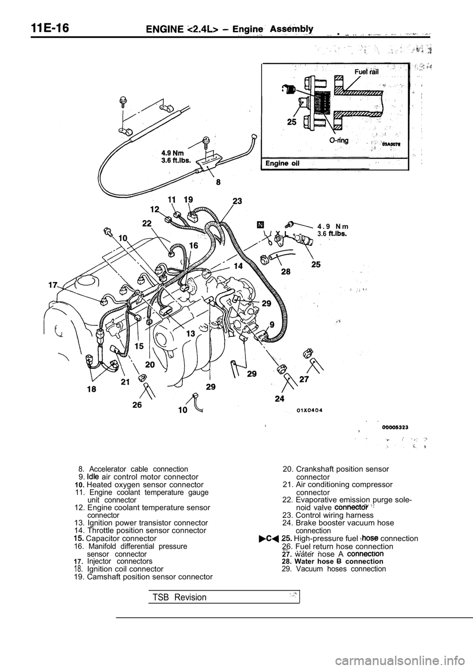
8. Accelerator cable connection9. air control motor connector
10. Heated oxygen sensor connector
11. Engine coolant temperature gauge
unit connector
12. Engine coolant temperature sensorconnector13. Ignition power transistor connector
14. Throttle position sensor connector
Capacitor connector16. Manifold differential pressure
20. Crankshaft position sensor
connector21. Air conditioning compressor
connector22. Evaporative emission purge sole-
noid valve
23. Control wiring harness
24. Brake booster vacuum hose
connection High-pressure fuel connection
26. Fuel return hose connection --
. .. .
17.18.
sensor connector
Injector connectors
Ignition coil connector
19. Camshaft position sensor connector 27.
water nose A 28. Water hose connection29. Vacuum hoses connection
TSB Revision
Page 383 of 2103
ENGINE (NON-TURBO)> General
FUEL INJECTION
ENGINE (NON-TURBO)>
GENERAL INFORMATION
The Fuel Injection System consists
of sensors which detect the engine conditions,
the POWERTRAIN CONTROL MODULE(PCM) which controls the system based on
signals from these sensors, and actuators
which operate under the control of the PCM.
FUEL INJECTION CONTROL
The injector drive times and injector timing are
controlled so that the optimum air/fuel mixture
is supplied to the engine to correspond to the
continually-changing engine operation condi-
tions.
A single injector is mounted at the intake port
of each cylinder. Fuel is sent under pressure
from the fuel tank by the fuel pump, with the
pressure regulated by the fuel pressureregulator. The regulated fuel is distributed
to each of the injectors. Fuel injection is normally carried out once for
each cylinder for every two rotations of the
crankshaft. The firing order is
This
IDLE AIR CONTROL The idle speed’ is kept at the optimum speed
by controlling the amount of air that bypasses
the throttle valve in accordance with changes in idling conditions and engine load during
idling.
The PCM drives the idle air control (IAC) motor
to keep the engine running at the idle
target speed in accordance with the engine
IGNITION TIMING CONTROL
The ignition power transistor is built into the
PCM. It turns the ignition primary circuit on
and off to respectively supply and cut off primary
current flow to the ignition coil. The PCM carries
activities such fuel
injection control, idle air control and ignition
timing control.
In addition, the
diagnostict e s twhich simplify
troubleshooting when a problem develops.
is called The PCM
air/fuel mixture by carrying out “open-loop”
control when the engine is cold or operating
under high load conditions in to maintain
engine performance.
In addition, when the engine warm or
operating under normal
the PCM
controls the air/fuel mixture by using the heated
oxygen sensor signal to carry out “closed-loop”
control in order to obtain the theoretical air/fuel
mixture ratio that provides the maximum
cleaning
from the three way
catalyst.
coolant temperature and air conditioning load.
In addition, when the air conditioning switch
is turned off and on while the engine is idling,
the
motor operates to adjust the throttle
valve bypass air amount in accordance with
the engine load conditions in order to avoid
fluctuations in the engine speed.
This controls the ignition timing in order to
provide the optimum ignition timing with respect
to the engine operating conditions. The ignition
timing is determined by the PCM from the
engine speed, intake air volume, engine coolant
temperature and atmospheric pressure.
TSB Revision
Page 518 of 2103
ENGINE
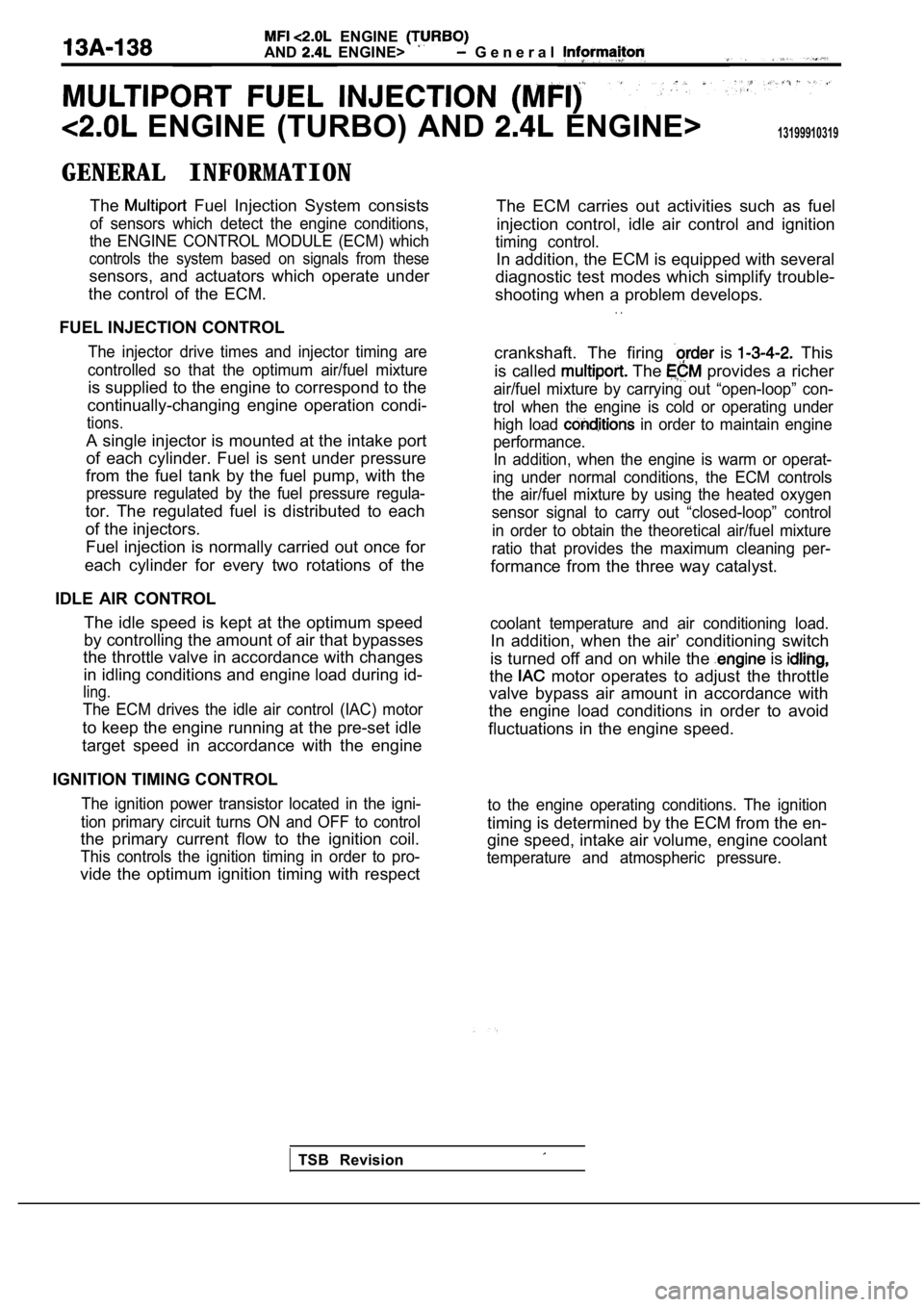
AND ENGINE> G e n e r a l
ENGINE (TURBO) AND ENGINE>13199910319
GENERAL INFORMATIONThe
Fuel Injection System consists
of sensors which detect the engine conditions,
the ENGINE CONTROL MODULE (ECM) which
controls the system based on signals from these
sensors, and actuators which operate under
the control of the ECM.
FUEL INJECTION CONTROL
The injector drive times and injector timing are
controlled so that the optimum air/fuel mixture
is supplied to the engine to correspond to the
continually-changing engine operation condi-
tions.
A single injector is mounted at the intake port
of each cylinder. Fuel is sent under pressure
from the fuel tank by the fuel pump, with the
pressure regulated by the fuel pressure regula-
tor. The regulated fuel is distributed to each
of the injectors.
Fuel injection is normally carried out once for
each cylinder for every two rotations of the
IDLE AIR CONTROL The idle speed is kept at the optimum speed
by controlling the amount of air that bypasses
the throttle valve in accordance with changes
in idling conditions and engine load during id-
ling.
The ECM drives the idle air control (IAC) motor
to keep the engine running at the pre-set idle
target speed in accordance with the engine
IGNITION TIMING CONTROL
The ignition power transistor located in the igni-
tion primary circuit turns ON and OFF to control
the primary current flow to the ignition coil.
This controls the ignition timing in order to pro-
vide the optimum ignition timing with respect The ECM carries out activities such as fuel
injection control, idle air control and ignition
timing control.
In addition, the ECM is equipped with several
diagnostic test modes which simplify trouble-
shooting when a problem develops.
. .
crankshaft. The firing is This
is called
The provides a richer
air/fuel mixture by carrying out “open-loop” con-
trol when the engine is cold or operating under high load
in order to maintain engine
performance. In addition, when the engine is warm or operat-
ing under normal conditions, the ECM controls
the air/fuel mixture by using the heated oxygen
sensor signal to carry out “closed-loop” control
in order to obtain the theoretical air/fuel mixture
ratio that provides the maximum cleaning per-
formance from the three way catalyst.
coolant temperature and air conditioning load.
In addition, when the air’ conditioning switch
is turned off and on while the
is
the motor operates to adjust the throttle
valve bypass air amount in accordance with
the engine load conditions in order to avoid
fluctuations in the engine speed.
to the engine operating conditions. The ignition
timing is determined by the ECM from the en-
gine speed, intake air volume, engine coolant
temperature and atmospheric pressure.
TSB Revision
Page 652 of 2103
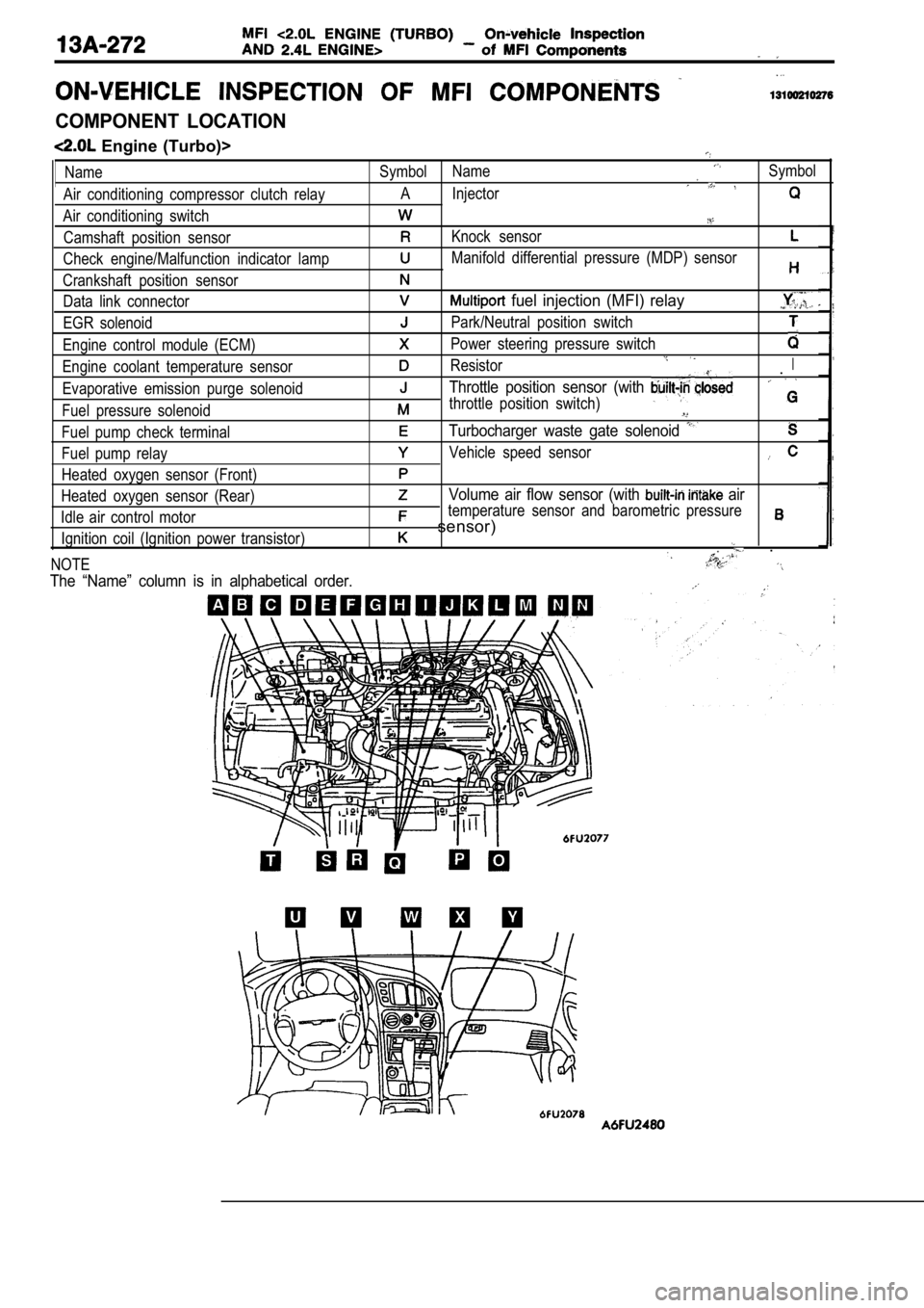
COMPONENT LOCATION
Engine (Turbo)>
Name
Air conditioning compressor clutch relay
Air conditioning switch Camshaft position sensor
Check engine/Malfunction indicator lamp
Crankshaft position sensor Data link connector
EGR solenoid
Engine control module (ECM)
Engine coolant temperature sensor
Evaporative emission purge solenoid
Fuel pressure solenoid
Fuel pump check terminal
Fuel pump relay
Heated oxygen sensor (Front)
Heated oxygen sensor (Rear)
Idle air control motor Ignition coil (Ignition power transistor)
NOTESymbol NameSymbol
A Injector
Knock sensor
Manifold differential pressure (MDP) sensor
fuel injection (MFI) relay
Park/Neutral position switch
Power steering pressure switch
ResistorI.
Throttle position sensor (with
throttle position switch)
Turbocharger waste gate solenoid
Vehicle speed sensor
Volume air flow sensor (with air
temperature sensor and barometric pressure
sensor)
.
The “Name” column is in alphabetical order.
Page 656 of 2103
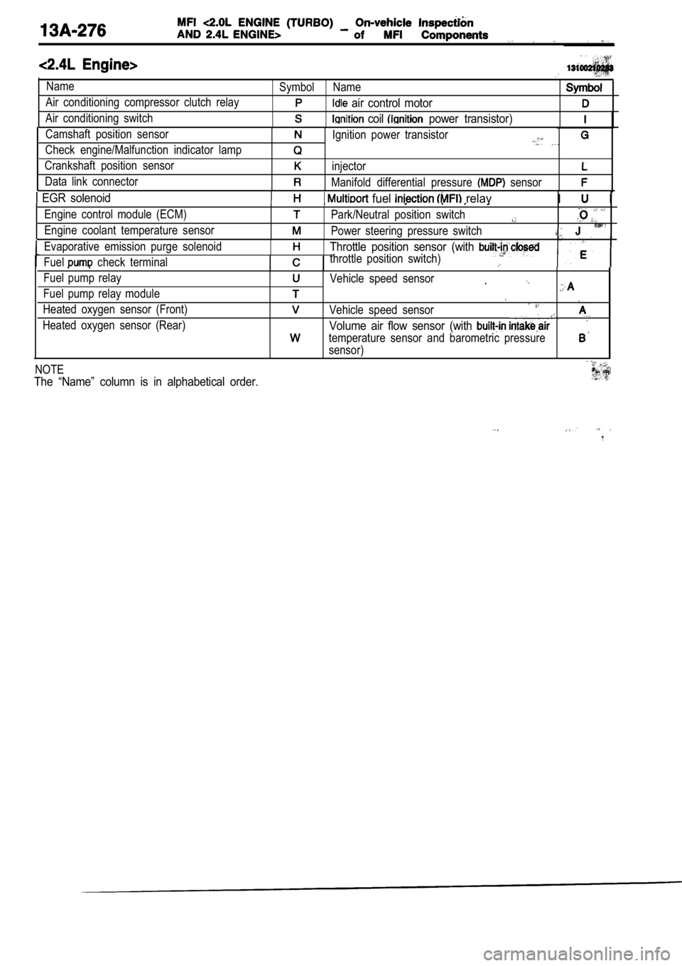
Name
Air conditioning compressor clutch relay
Air conditioning switchSymbol Name
air control motor
coil power transistor)
Camshaft position sensor
Check engine/Malfunction indicator lamp
Crankshaft position sensor
Data link connectorIgnition power transistor
injector
Manifold differential pressure sensor
EGR solenoid fuel relavI I
Engine control module (ECM)
Engine coolant temperature sensorPark/Neutral position switch
Power steering pressure switch
Evaporative emission purge solenoid
Fuel
check terminal
Throttle position sensor (with
throttle position switch)
Fuel pump relay
Fuel pump relay module
Heated oxygen sensor (Front)
Heated oxygen sensor (Rear)Vehicle speed sensor.
Vehicle speed sensor
Volume air flow sensor (with
temperature sensor and barometric pressure
sensor)
NOTE
The “Name” column is in alphabetical order.
Page 696 of 2103
14-6ENGINE COOLING
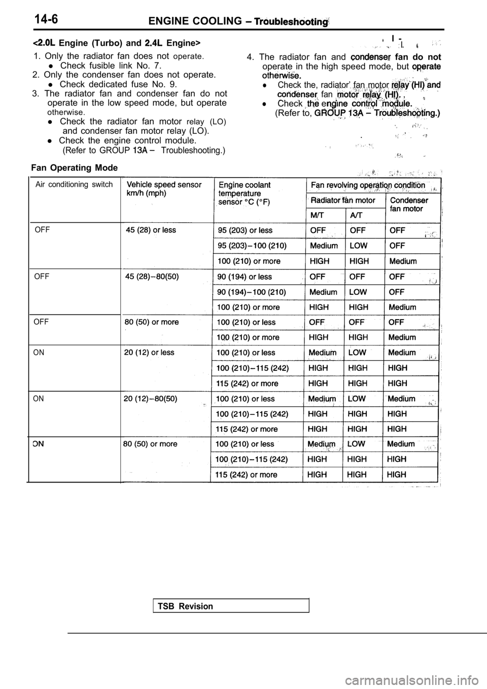
Engine (Turbo) and Engine>
1. Only the radiator fan does not operate.
l Check fusible link No. 7.
2. Only the condenser fan does not operate.
l Check dedicated fuse No. 9.
3. The radiator fan and condenser fan do not operate in the low speed mode, but operate
otherwise.
l Check the radiator fan motor relay (LO)
and condenser fan motor relay (LO).
l Check the engine control module.
(Refer to GROUP Troubleshooting.)
I -* I.
4. The radiator fan and fan do not
Fan Operating Mode operate in the high speed mode, but
lCheck the, radiator’ fan motor
fan ,
lCheck en
(Refer to,
.
Air conditioning switch
OFF
OFF
OFF
ON
ON
TSB Revision