1990 MITSUBISHI SPYDER heater
[x] Cancel search: heaterPage 37 of 2103
GENERAL Recommended Lubricants and Lubricant Table
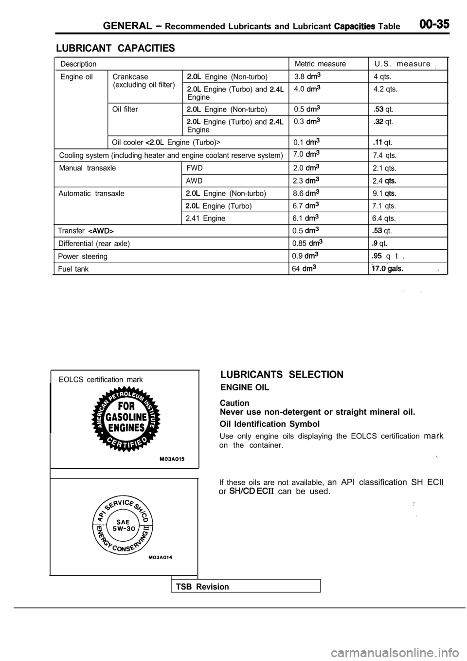
LUBRICANT CAPACITIES
DescriptionMetric measureU . S . m e a s u r e
Engine oil Crankcase Engine (Non-turbo)3.8
(excluding oil filter) 4 qts. Engine (Turbo) and 4.0
Engine4.2 qts.
Oil filter
Engine (Non-turbo) 0.5 qt.
Engine (Turbo) and 0.3
Engine
qt.
Oil cooler
Engine (Turbo)> 0.1 qt.
Cooling system (including heater and engine coolant reserve system)7.07.4 qts.
Manual transaxleFWD2.02.1 qts.
AWD2.32.4
Automatic transaxle Engine (Non-turbo)8.69.1
Engine (Turbo)
6.77.1 qts.
2.41 Engine 6.16.4 qts.
Transfer
0.5 qt.
Differential (rear axle) 0.85
qt.
Power steering
0.9 q t .
Fuel tank 64
EOLCS certification markLUBRICANTS SELECTION
ENGINE OIL
Caution
Never use non-detergent or straight mineral oil.
Oil Identification Symbol
Use only engine oils displaying the EOLCS certifica tion mark
on the container.
If these oils are not available, an API classification SH ECII
or
can be used.
TSB Revision
Page 50 of 2103
GENERAL Maintenance Service
,
Revision
Drain Plug
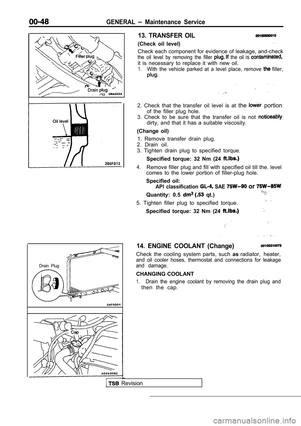
13. TRANSFER OIL
(Check oil level)
Check each component for evidence of leakage, and-check
the oil level by removing the filler the oil is
it is necessary to replace it with new oil.
1.With the vehicle parked at a level place, remove filler,
2. Check that the transfer oil level is at the portion
of the filler plug hole.
3. Check to be sure that the transfer oil is not
dirty, and that it has a suitable viscosity.
(Change oil) 1. Remove transfer drain plug.
2. Drain oil.
3. Tighten drain plug to specified torque.
Specified torque: 32 Nm (24
4.Remove filler plug and fill with specified oil till the. level
comes to the lower portion of filler-plug hole.
Specified oil:
API classification SAE or
Quantity: 0.5 qt.)
5. Tighten filler plug to specified torque.
Specified torque: 32 Nm (24
14. ENGINE COOLANT (Change)
Check the cooling system parts, such asradiator, heater,
and oil cooler hoses, thermostat and connections fo r leakage
and damage.
CHANGING COOLANT
1.Drain the engine coolant by removing the drain plug and
then the cap.
Page 185 of 2103
ENGINE
Fuelrail
Engine oil
2.5 Nm
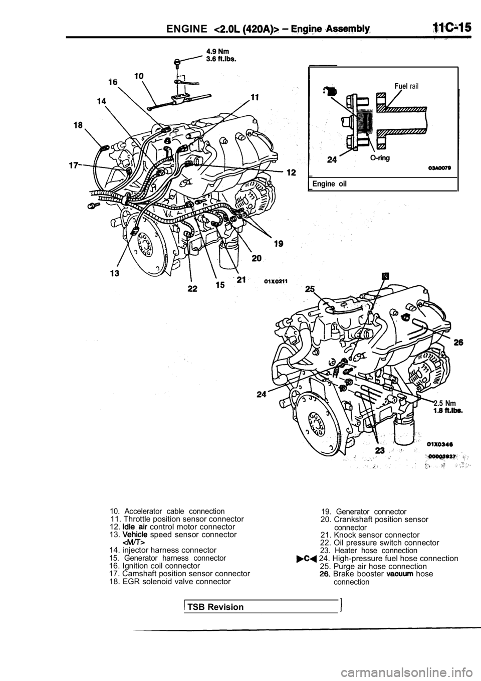
10. Accelerator cable connection11. Throttle position sensor connector
12. control motor connector
13. speed sensor connector
14. injector harness connector
15. Generator harness connector16. Ignition coil connector
17. Camshaft position sensor connector 18. EGR solenoid valve connector
19. Generator connector20. Crankshaft position sensor
connector21. Knock sensor connector
22. Oil pressure switch connector
23. Heater hose connection 24. High-pressure fuel hose connection
25. Purge air hose connection
Brake booster hose
connection
TSB Revision
Page 200 of 2103
ENGINE Cylinder Head
4.9 Nm
10
Engine oil
TSB Revision
2
15
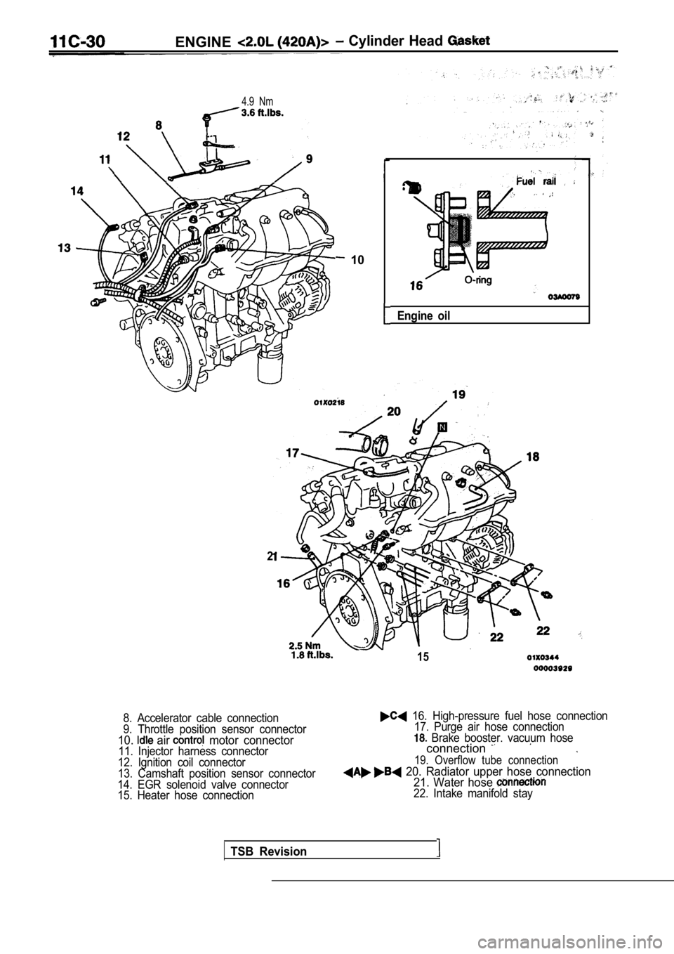
8. Accelerator cable connection
9. Throttle position sensor connector
10. air motor connector11. Injector harness connector
12. Ignition coil connector
13. Camshaft position sensor connector
14. EGR solenoid valve connector
15. Heater hose connection
16. High-pressure fuel hose connection 17. Purge air hose connection
Brake booster. vacuum hoseconnection
19. Overflow tube connection
20. Radiator upper hose connection 21. Water hose
22. Intake manifold stay
Page 389 of 2103
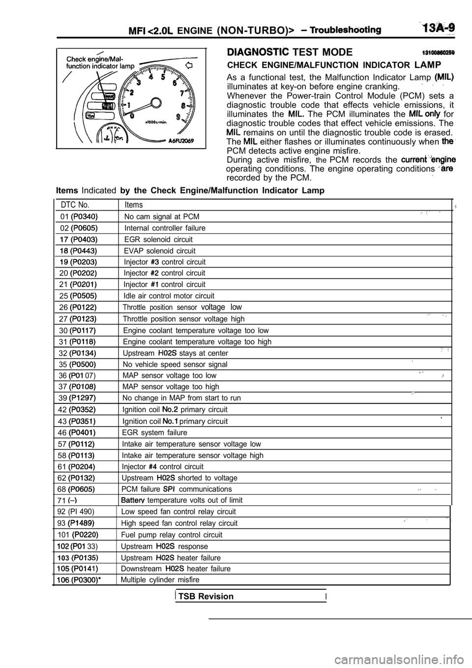
ENGINE (NON-TURBO)>
TEST MODE
CHECK ENGINE/MALFUNCTION INDICATOR LAMP
As a functional test, the Malfunction Indicator Lam p
illuminates at key-on before engine cranking.
Whenever the Power-train Control Module (PCM) sets a
diagnostic trouble code that effects vehicle emissi ons, it
illuminates the
The PCM illuminates the for
diagnostic trouble codes that effect vehicle emissi ons. The
remains on until the diagnostic trouble code is erased.
The
either flashes or illuminates continuously when
PCM detects active engine misfire.
During active misfire, thePCM records the
operating conditions. The engine operating conditio ns
recorded by the PCM.
ItemsIndicated by the Check Engine/Malfunction Indicator Lamp
DTC No. Items
01No cam signal at PCM
02Internal controller failure
EGR solenoid circuit
EVAP solenoid circuit
Injector control circuit
20Injector control circuit
21Injector control circuit
25Idle air control motor circuit
26Throttle position sensor voltage low
27Throttle position sensor voltage high
30Engine coolant temperature voltage too low
31Engine coolant temperature voltage too high
32Upstream stays at center
35
No vehicle speed sensor signal
36
07) MAP sensor voltage too low
37MAP sensor voltage too high
39No change in MAP from start to run
42Ignition coil primary circuit
43Ignition coil primary circuit
46
EGR system failure
57Intake air temperature sensor voltage low
58Intake air temperature sensor voltage high
61Injector control circuit
62Upstream shorted to voltage
68PCM failure communications
71 temperature volts out of limit
, .
,
92 (PI 490)
93
101
33)
103
Low speed fan control relay circuit
High speed fan control relay circuit
Fuel pump relay control circuit
Upstream
response
Upstream
heater failure
Downstream
heater failure
Multiple cylinder misfire
TSB RevisionI
Page 400 of 2103
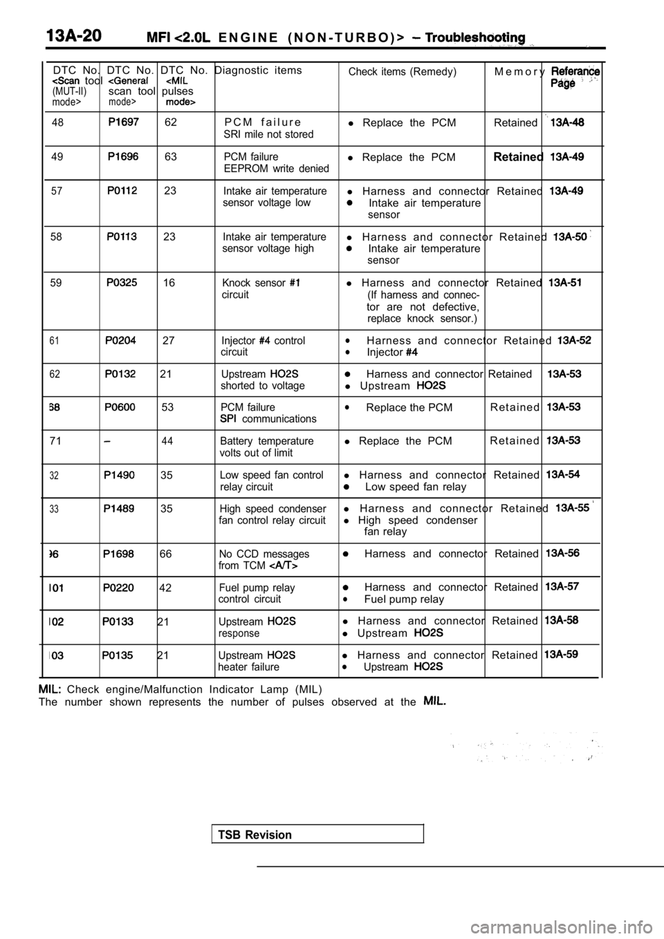
E N G I N E ( N O N - T U R B O ) >
DTC No. DTC No. DTC No. Diagnostic items tool (MUT-II)scan tool pulsesmode>mode>
48 62 P C M f a i l u r e
SRI mile not storedCheck items (Remedy)
l
Replace the PCM M e m o r yRetained
49 63PCM failurel
Replace the PCM Retained
EEPROM write denied
57 23Intake air temperaturel Harness and connector Retained
sensor voltage lowIntake air temperature
sensor
58
23Intake air temperaturel H a r n e s s a n d c o n n e c t o r R e t a i n e d
sensor voltage highIntake air temperature
sensor
59
16Knock sensor
circuit
l Harness and connector Retained
(If harness and connec-
tor are not defective,
replace knock sensor.)
61 27
62 21
53
Injector control
circuit
Upstream
shorted to voltage
PCM failure
communications
lH a r n e s s a n d c o n n e c t o r R e t a i n e d lInjector
Harness and connector Retained
l Upstream
lReplace the PCM R e t a i n e d
7144Battery temperature
volts out of limitl Replace the PCM R e t a i n e d
32 35
33 35
Low speed fan controll
Harness and connector Retained
relay circuitLow speed fan relay
High speed condenserl H a r n e s s a n d c o n n e c t o r R e t a i n e d
fan control relay circuitl High speed condenser
fan relay
66No CCD messages
from TCM Harness and connector Retained
42
21
21
Fuel pump relay
control circuit
Upstream
response
Upstream
heater failure
Harness and connector Retained
lFuel pump relay
l Harness and connector Retained
l Upstream
l Harness and connector Retained lUpstream
Check engine/Malfunction Indicator Lamp (MIL)
The number shown represents the number of pulses ob served at the
TSB Revision
Page 401 of 2103
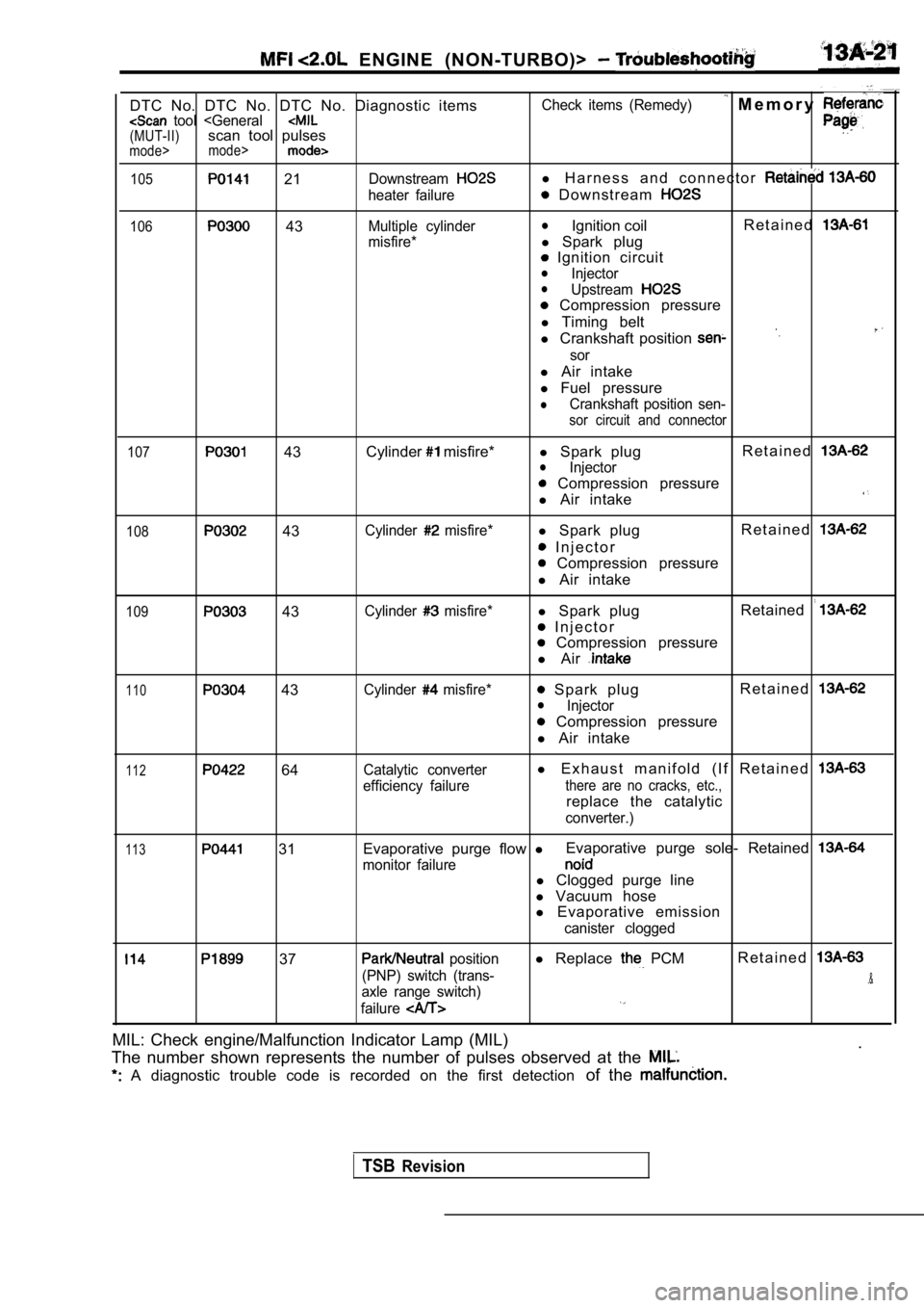
ENGINE (NON-TURBO)>
DTC No. DTC No. DTC No. Diagnostic items tool
105 21Downstream
heater failure
106 43Multiple cylinder
misfire* Check items (Remedy)
M e m o r y
l
H a r n e s s a n d c o n n e c t o r
D o w n s t r e a m
lIgnition coil R e t a i n e d
l
Spark plug
Ignition circuitlInjectorlUpstream
Compression pressure
l Timing belt
l Crankshaft position
sor
l Air intake
l Fuel pressure
lCrankshaft position sen-
sor circuit and connector
107
43 Cylinder misfire*
l Spark plug R e t a i n e dlInjector
Compression pressure
l Air intake
108 43Cylinder misfire*l Spark plug R e t a i n e d
I n j e c t o r
Compression pressure
l Air intake
109 43Cylinder misfire*l Spark plug Retained
I n j e c t o r
Compression pressure
l Air
110 43Cylinder misfire* Spark plug R e t a i n e dlInjector
Compression pressure
l Air intake
112 64Catalytic converter
efficiency failurel E x h a u s t m a n i f o l d ( I f R e t a i n e d
there are no cracks, etc.,
replace the catalytic
converter.)
113 31 Evaporative purge flow
lEvaporative purge sole- Retained
monitor failurel
Clogged purge line
l Vacuum hose
l Evaporative emission
canister clogged
37 position
(PNP) switch (trans-
axle range switch)
failurel Replace PCMR e t a i n e d
.&
MIL: Check engine/Malfunction Indicator Lamp (MIL)
.
The number shown represents the number of pulses ob served at the
A diagnostic trouble code is recorded on the first detection of the
TSBRevision
Page 433 of 2103
![MITSUBISHI SPYDER 1990 Service Repair Manual ENGINE (NON-TURBO)>
NG Replace
Scan tool 62
Code General scan tool Upstream Shorted to Volt;
No.
21
[Comment]l Heated oxygen sensor failedBackgroundl W i r i n glUpstream heated MITSUBISHI SPYDER 1990 Service Repair Manual ENGINE (NON-TURBO)>
NG Replace
Scan tool 62
Code General scan tool Upstream Shorted to Volt;
No.
21
[Comment]l Heated oxygen sensor failedBackgroundl W i r i n glUpstream heated](/manual-img/19/57345/w960_57345-432.png)
ENGINE (NON-TURBO)>
NG Replace
Scan tool 62
Code General scan tool Upstream Shorted to Volt;
No.
21
[Comment]l Heated oxygen sensor failedBackgroundl W i r i n glUpstream heated oxygen sensor requires a heater cir cuit for proper operation.
l PCM,
l The heater circuit is supplied with battery voltage through the
relay relay):lA failure in the sensors heater circuit prevents it from providing accurate data to the PCM.l the PCM monitors more than 1.2 volts, the sensor h as shorted to heater circuit voltage.Range of Checkl Two or more minutes after the engine startsl Engine coolant temperature: or moreSet Conditionl Heated oxygen sensor output voltage is more than 1. 2 for 3 seconds.
OK
OKNG Repair
Check trouble symptom.
NGNGCheck the harness wire between the PCM and the heat ed oxygen Repairsensor (front).
OK
Replace the PCM.
Scan tool 68
Code General scan tool PCM Failure
No. Communications
53
[Comment]Set Condition
l There is no communication between in the control module.
Probable cause
l PCM failed
the PCM.
Probable cause
[Comment] BackgroundlBattery temperature input is used to adjust the gen erator charging rate based upon the
ambient temperature around the battery.
Range of Check
l
switch: ON
Set Condition
lThe sensor voltage is not within the acceptable ran ge of 0.3 to 4.9 volts for 3 seconds
or more. l
Battery temperature sensor failed
l PCM failed
Replace the PCM.
TSB Revision