1990 MITSUBISHI SPYDER battery
[x] Cancel search: batteryPage 7 of 2103

GENERAL How to Use This Manual
1 S T E E R I N G
Power Steering Gear B
O X
POWER STEERING GEAR BOX
6
gear
.
TIE-ROD END
.Operating procedures, etc. on removal, assembly
1. sun tie the cord of the special tool described.
2.Loosen the nut but do not
FOG LIGHT RELAY CHECK
I indicates that there is134 ,continuity’ between the o - - - anals.
supplied indicates terminals‘ to
which battery
S T E E R I N G Power Steering Box
Page 14 of 2103

GENERAL How to Use Troubleshooting/Inspection
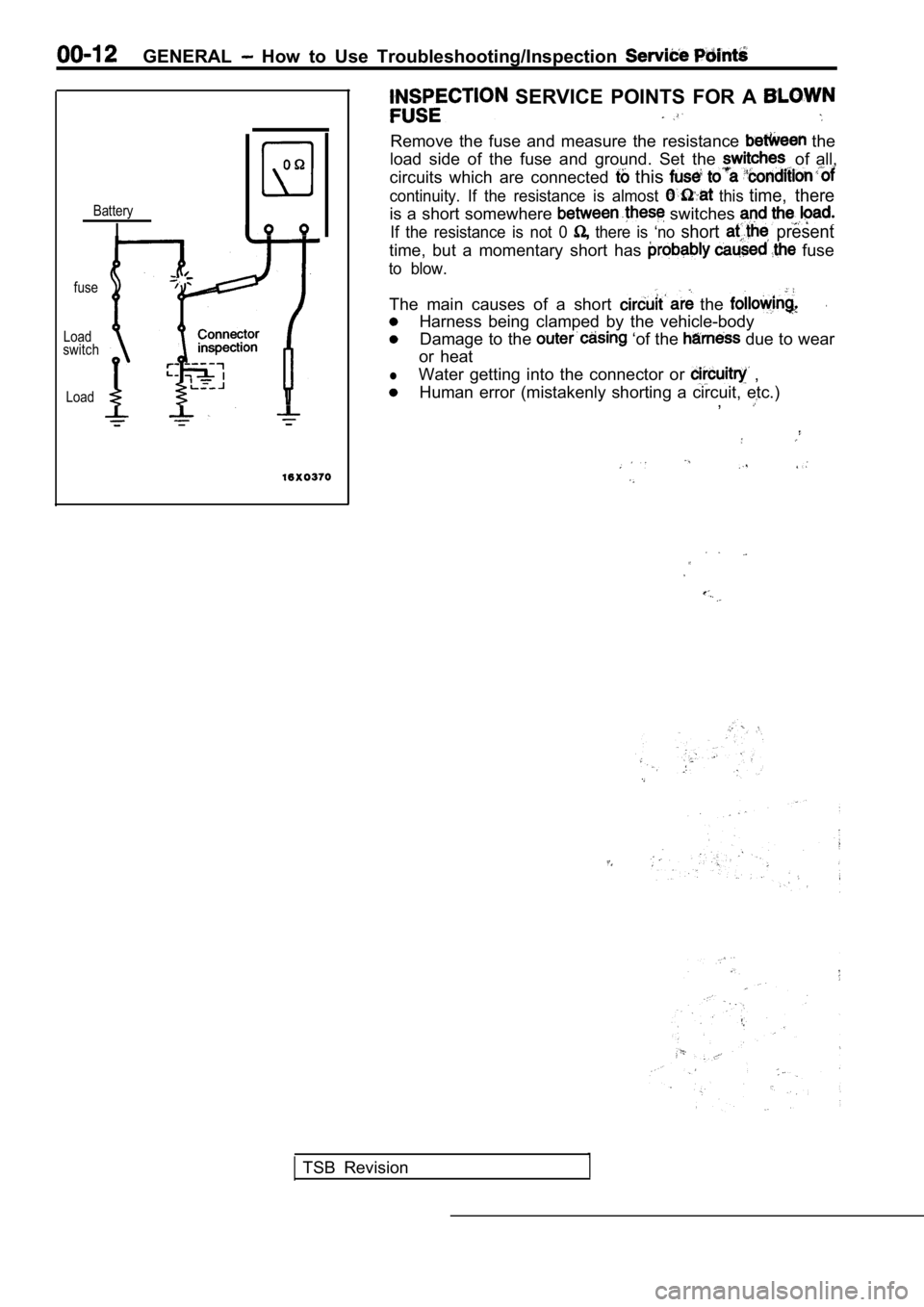
SERVICE POINTS FOR A
Remove the fuse and measure the resistance the
load side of the fuse and ground. Set the of all,
circuits which are connected
this
continuity. If the resistance is almost this time, thereBatteryis a short somewhere switches
IIf the resistance is not 0 there is ‘no short present
time, but a momentary short has fuse
to blow.
fuse
The main causes of a short the .
Harness being clamped by the vehicle-bodyLoadswitchDamage to the ‘of the due to wear
or heat
lWater getting into the connector or ,
LoadHuman error (mistakenly shorting a circuit, etc.) ,
TSB Revision
Page 22 of 2103

GENERAL before Service
PRECAUTIONS BEFORE SERVICE.
SUPPLEMENTAL RESTRAINT SYSTEM
1. to follow when servicing SRS
(1) Be sure to read GROUP Supplemental Restraint System
For safe operations, please follow the directions a nd heed all
(2) Always use the designated special tools and tes t equipment.
(3) Wait at least 60 seconds after disconnecting the battery cable before” further work;
The SRS system is designed to retain enough voltage to deploy the air bag even after the battery
has been disconnected. Serious injury may result from unintended air bag deployment if work
is done on the SRS system immediately after the bat tery cable is disconnected.
(4) Never attempt to disassemble or repair the SRS components (SRS-ECU air bag module and
clock spring). If faulty, replace it.
(5) Warning labels must be heeded when servicing or handling SRS components. Warning labels
are located in the following locations.
Sun visor
l Glove box
. S R S - E C U
l Steering wheel
l Air bag module
l Clock spring
l Steering gear and linkage clamp
(6) Store components removed from the SRS
a clean and dry place.
The air bag module should be stored on a flat surfa ce and placed so that the pad surface is’
facing upward.
Do not place anything on top of it.
(7) Be sure to deploy the air bag before disposing of the air bag’module or disposing of a vehicle
equipped with an air bag. (Refer to GROUP
Air Bag Module Disposal Procedures.)
(8) Whenever you finish servicing the
check the SRS warning light operation to make sure
that the system functions properly.
2.Observe the following when carrying out operations on places where SRS components are installed,’
.,
including operations not directly related to the SR S air bag.
(1) When removing or installing parts do not allow any impact or shock to the SRS components.
(2) SRS components should not be subjected to heat over so remove the SRS compo-
nents before drying or baking the vehicle after painting.
After re-installing them, check the SRS warning lig ht operation to make sure that the system
functions properly.
SERVICING THE ELECTRICAL SYSTEM
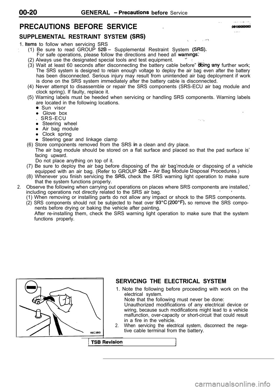
1. Note the following before proceeding with work o n the
electrical system.
Note that the following must never be done:
Unauthorized modifications of any electrical device or
wiring, because such modifications might lead to a vehicle
malfunction, over-capacity or short-circuit that co uld result
in a fire in the vehicle.
2.When servicing the electrical system, disconnect th e nega-
tive cable terminal from the battery.
Page 53 of 2103

GENERAL Maintenance
21 SYSTEM component
damage, to wiring,
harness, etc.)
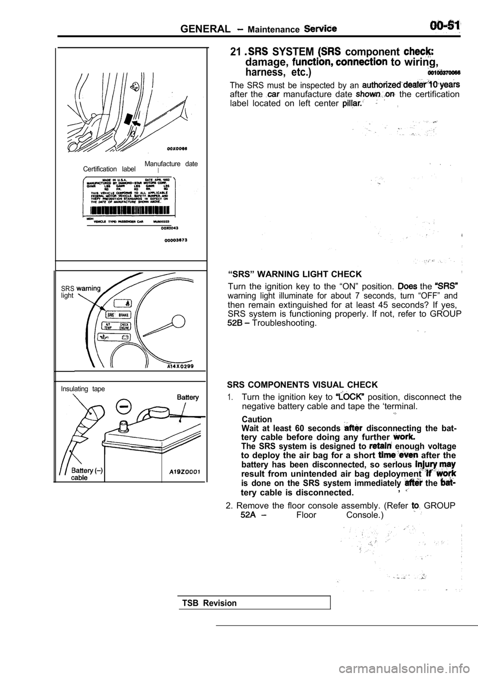
Certification labelManufacture dateI
SRSlight
Insulating tape
The SRS must be inspected by an
after the manufacture date the certification
label located on left center
,
“SRS” WARNING LIGHT CHECK,
Turn the ignition key to the “ON” position. the
warning light illuminate for about 7 seconds, turn “OFF” and
then remain extinguished for at least 45 seconds? I f yes,
SRS system is functioning properly. If not, refer t o GROUP
Troubleshooting.
SRS COMPONENTS VISUAL CHECK
1.Turn the ignition key to position, disconnect the
negative battery cable and tape the ‘terminal.
Caution
Wait at least 60 seconds
disconnecting the bat-
tery cable before doing any further
The SRS system is designed to enough voltage
to deploy the air bag for a short after the
battery has been disconnected, so serlous
result from unintended air bag deployment
is done on the SRS system immediately the
tery cable is disconnected. ,
2. Remove the floor console assembly. (Refer GROUP
Floor Console.)
TSB Revision
Page 71 of 2103

ENGINE On-vehicle
8. If the standard value is exceeded, check the following
items:
l Diagnostic output
l Closed-loop control (When the closed-loop control
is carried out normally, the output signal of the h eated
oxygen sensor repeats between and
,000 at idle.)
l Fuel pressure
I n j e c t o r
lIgnition coil, spark plug cable, spark plug
lEGR system and the EGR valve leak
l Evaporative emission control system
Compression pressure
NOTE
Replace the catalyst whenever the
HC contents do not remain inside the standard value .
(even though the result of the inspection is
all items.).
C O M P R E S S I O N
CHECK
1.Before inspection, check that the engine-oil, start er
battery are normal. Also, set the to the
condition:
lEngine coolant temperature:
lLights, electric cooling fan and all accessories: O FF
lTransaxle: Neutral (P range on vehicles with
2. Disconnect the spark plug cables.
3. Remove all of the spark plugs.
4.
5.
Disconnect the crankshaft position sensor connector .
NOTE
Doing this will prevent the engine control unit fro m carrying
out ignition and fuel injection.
Cover the spark plug hole with a shop towel etc., a nd
after the engine has been cranked, check that no fo reign
material is adhering to the shop towel.
TSB Revision
Page 72 of 2103

ENGINE On-vehicle
Caution
1.Keep away from the spark plug hole when crank-
ing.
2. If compression is measured with water, oil, fuel,
etc., that has come from cracks inside the cylinder ,
these materials will become heated and will gush
out from the spark plug hole, which is dangerous.
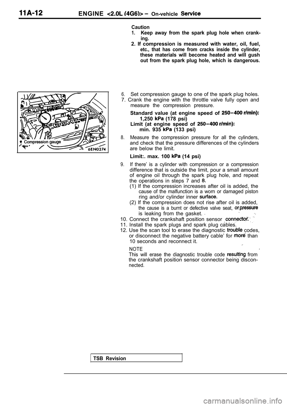
6.Set compression gauge to one of the spark plug hole s.
7. Crank the engine with the throttle valve fully o pen and
measure the compression pressure.
Standard value (at engine speed of
1,250 (178 psi)
Limit (at engine speed of
min. 935 (133 psi)
8.Measure the compression pressure for all the cylind ers,
and check that the pressure differences of the cylinders
are below the limit.
Limit:. max. 100
(14 psi)
9.If there’ is a cylinder with compression or a compr ession
difference that is outside the limit, pour a small amount
of engine oil through the spark plug hole, and repe at
the operations in steps 7 and
(1) If the compression increases after oil is added , the
cause of the malfunction is a worn or damaged pisto n
ring and/or cylinder inner
(2) If the compression does not rise after oil is added,
the cause is a burnt or defective valve seat,
is leaking from the gasket.
10. Connect the crankshaft position sensor
11. Install the spark plugs and spark plug cables.
12. Use the scan tool to erase the diagnostic
codes,
or disconnect the negative battery cable’ for
than
10 seconds and reconnect it.
NOTE
This will erase the diagnostic trouble code from
the crankshaft position sensor connector being disc on-
nected.
TSB Revision
Page 181 of 2103

ENGINE On-vehicle Service
IDLE MIXTURE CHECK
11100210081
1.Before inspection, set vehicles in the following co ndition:
lEngine coolant temperature:
l Lights, electric cooling fan and all accessories: O FF
lTransaxle: Neutral (P range on vehicles with
2.After turning the ignition switch to OFF, connect t he scan
tool to the data link connector.
3.Start the engine and run it at 2,500 for 2 minutes.
4. Set the CO, HC tester.
5. Check the CO contents and the HC contents at idl e.
Standard value:
CO contents: 0.5% or less
HC contents: 100 ppm or less
6. If the idle speed is outside the standard value, check
the following items: l Diagnostic output
l Closed-loop control (When the closed-loop control
is carried out normally, the output signal of the h eated
oxygen sensor repeats between and
,000 at idle.)
l Fuel pressure
I n j e c t o r
lIgnition coil, spark plug cable, spark plug
lEGR system and the EGR valve leak
l Evaporative emission control system
Compression pressure
NOTE
Replace the three-way catalyst whenever the CO and
HC contents do not remain inside the standard value .
(even though the result of the inspection is normal on
all items.)
COMPRESSION PRESSURE CHECK
1.Before inspection, check that the engine oil, start er and
battery are normal. Also, set the vehicle to the fo llowing
condition:
lEngine coolant temperature:
lLights, electric cooling fan and all accessories: O FF
lTransaxle: Neutral (P range on vehicle with
2. Disconnect the spark plug cables.
3. Remove all spark plugs.
4.Disconnect the relay (ASD relay) connector to prevent
a spark.
4 4
Revision
Page 279 of 2103

On-vehicle
Run the engine.
8. Set CO, HC tester.
7. Check the CO contents and the HC contents at idle.
Standard value:
CO contents: 0.5% or less
HC contents: 100 ppm or less
8. the standard value is exceeded, check the following
items:
l Diagnostic output
l Closed-loop control (When the closed-loop control
is carried out normally, the output signal of the heated
oxygen sensor and
at idle.)
l
Injector
lIgnition coil, spark plug
l system the
l Evaporative emission
Compression ,
NOTE,
Replace the three-way CO and
HC contents do not
the value.
(even though the
of the” on
all items.)
PRESSURE CHECK
1.Before inspection, check that the engine oil, start er and
battery are normal. Also, set the vehicle to the fo llowing
condition:
lEngine coolant temperature:
lLights, electric cooling fan and all accessories: O FF
lTransaxle: Neutral (P range on vehicles with
2. Disconnect the spark plug cables.
3. Remove all of the spark plugs.
4. Disconnect the crankshaft position sensor
NOTE
Doing this will prevent the engine control unit fro m carrying
out ignition and fuel injection.
TSB Revision