1990 MITSUBISHI SPYDER relay
[x] Cancel search: relayPage 7 of 2103

GENERAL How to Use This Manual
1 S T E E R I N G
Power Steering Gear B
O X
POWER STEERING GEAR BOX
6
gear
.
TIE-ROD END
.Operating procedures, etc. on removal, assembly
1. sun tie the cord of the special tool described.
2.Loosen the nut but do not
FOG LIGHT RELAY CHECK
I indicates that there is134 ,continuity’ between the o - - - anals.
supplied indicates terminals‘ to
which battery
S T E E R I N G Power Steering Box
Page 181 of 2103

ENGINE On-vehicle Service
IDLE MIXTURE CHECK
11100210081
1.Before inspection, set vehicles in the following co ndition:
lEngine coolant temperature:
l Lights, electric cooling fan and all accessories: O FF
lTransaxle: Neutral (P range on vehicles with
2.After turning the ignition switch to OFF, connect t he scan
tool to the data link connector.
3.Start the engine and run it at 2,500 for 2 minutes.
4. Set the CO, HC tester.
5. Check the CO contents and the HC contents at idl e.
Standard value:
CO contents: 0.5% or less
HC contents: 100 ppm or less
6. If the idle speed is outside the standard value, check
the following items: l Diagnostic output
l Closed-loop control (When the closed-loop control
is carried out normally, the output signal of the h eated
oxygen sensor repeats between and
,000 at idle.)
l Fuel pressure
I n j e c t o r
lIgnition coil, spark plug cable, spark plug
lEGR system and the EGR valve leak
l Evaporative emission control system
Compression pressure
NOTE
Replace the three-way catalyst whenever the CO and
HC contents do not remain inside the standard value .
(even though the result of the inspection is normal on
all items.)
COMPRESSION PRESSURE CHECK
1.Before inspection, check that the engine oil, start er and
battery are normal. Also, set the vehicle to the fo llowing
condition:
lEngine coolant temperature:
lLights, electric cooling fan and all accessories: O FF
lTransaxle: Neutral (P range on vehicle with
2. Disconnect the spark plug cables.
3. Remove all spark plugs.
4.Disconnect the relay (ASD relay) connector to prevent
a spark.
4 4
Revision
Page 182 of 2103
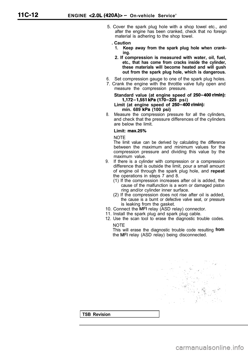
E N G I N E On-vehicle Service’
5. Cover the spark plug hole with a shop towel etc. , and
after the engine has been cranked, check that no foreign
material is adhering to the shop towel.
. Caution
1.Keep away from the spark plug hole when crank-
ing.
2. If compression is measured with water, oil, fuel ,
etc., that has come from cracks inside the cylinder ,
these materials will become heated and will gush
out from the spark plug hole, which is dangerous.
6.Set compression gauge to one of the spark plug hole s.
7. Crank the engine with the throttle valve fully o pen and
measure the compression pressure.
Standard value (at engine speed of
p s i )
Limit (at engine speed of
min. 689 (100 psi)
8.Measure the compression pressure for all the cylind ers,
and check that the pressure differences of the cylinders
are below the limit.
Limit:
NOTE
The limit value can be derived by calculating the d ifference
between the maximum and minimum values for the
compression pressure and dividing this value by the
maximum value.
9.If there is a cylinder with compression or a compre ssion
difference that is outside the limit, pour a small amount
of engine oil through the spark plug hole, and repeat
the operations in steps 7 and 8. (1) If the compression increases after oil is added , the
cause of the malfunction is a worn or damaged pisto n
ring and/or cylinder inner surface.
(2) If the compression does not rise after oil is a dded,
the cause is a burnt or defective valve seat, or pr essure
is leaking from the gasket.
10. Connect the
relay (ASD relay) connector.
11. Install the spark plug and spark plug cable.
12. Use the scan tool to erase the diagnostic troub le codes.
NOTE
This will erase the diagnostic trouble code resulti ng
the relay (ASD relay) being disconnected.
TSB Revision
Page 381 of 2103
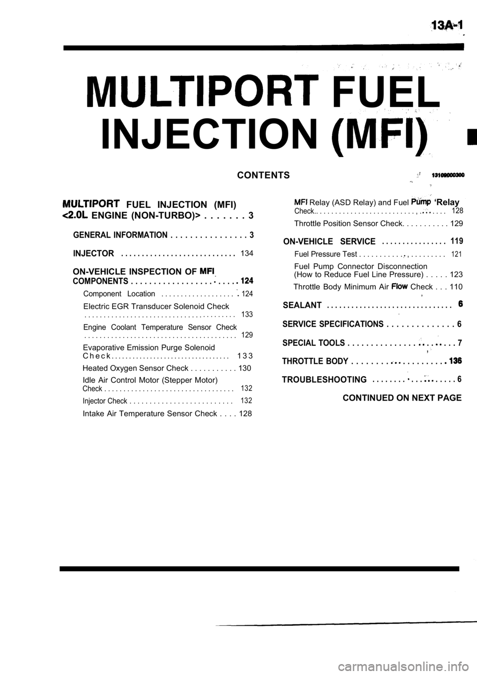
FUEL
INJECTION
CONTENTS
FUEL INJECTION (MFI)
ENGINE (NON-TURBO)> . . . . . . . 3
Relay (ASD Relay) and Fuel ‘Relay
Check.. . . . . . . . . . . . . . . . . . . . . . . . . . , . . . . .128
Throttle Position Sensor Check. . . . . . . . . . .
129
GENERAL INFORMATION . . . . . . . . . . . . . . . . 3ON-VEHICLE SERVICE. . . . . . . . . . . . . . . .119
INJECTOR. . . . . . . . . . . . . . . . . . . . . . . . . . . .134Fuel Pressure Test . . . . . . . . . . . , . . . . . . . . .121
ON-VEHICLE INSPECTION OF
COMPONENTS . . . . . . . . . . . . . . . . . . . . . .
Component Location. . . . . . . . . . . . . . . . . . . 124
Electric EGR Transducer Solenoid Check
. . . . . . . . . . . . . . . . . . . . . . . . . . . . . . .. . . . . . . . .133
Engine Coolant Temperature Sensor Check
. . . . . . . . . . . . . . . . . . . . . . . . . . . . . . . . . . . . . . . .129
Evaporative Emission Purge Solenoid
C h e c k . . . . . . . . . . . . . . . . . . . . . . . . . . . . . . . . . . 1 3 3
Heated Oxygen Sensor Check . . . . . . . . . . . 13 0
Idle Air Control Motor (Stepper Motor)
Check . . . . . . . . . . . . . . . . . . . . . . . . . . . . . . . . . .132
Injector Check . . . . . . . . . . . . . . . . . . . . . . . . . .132
Intake Air Temperature Sensor Check . . . . 128 Fuel Pump Connector Disconnection
(How to Reduce Fuel Line Pressure) . . . . . 123
Throttle Body Minimum Air
Check . . . 110 ,
SEALANT. . . . . . . . . . . . . . . . . . . . . . . . . . . . . . .
SERVICE SPECIFICATIONS . . . . . . . . . . . . . . 6
SPECIAL TOOLS . . . . . . . . . . . . . . .
. . . . . 7,
THROTTLE BODY . . . . . . . . . . . . . . . . .
TROUBLESHOOTING. . . . . . . . . . . . . . . . 6
CONTINUED ON NEXT PAGE
Page 382 of 2103
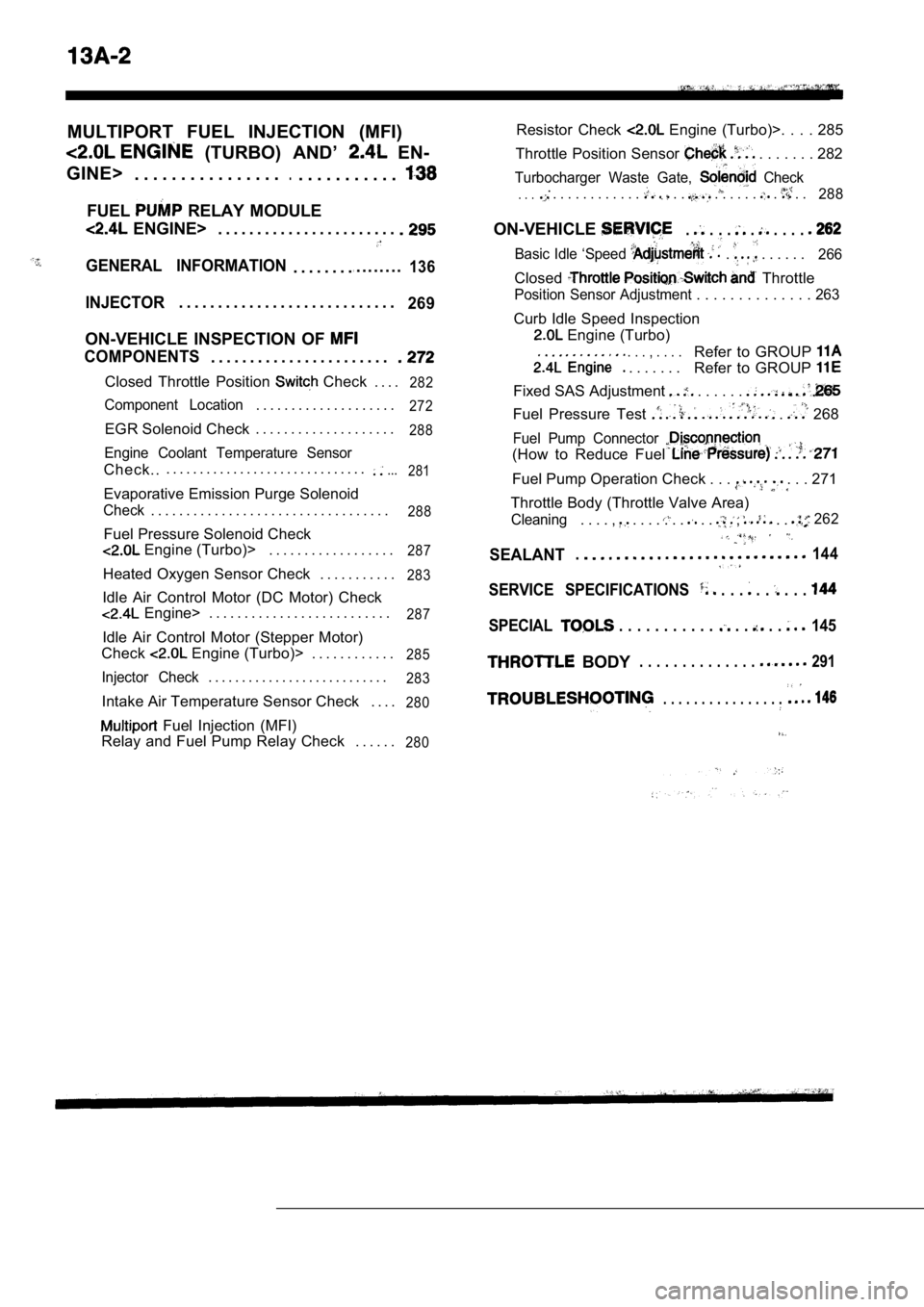
MULTIPORT FUEL INJECTION (MFI)
(TURBO) AND’ EN-
GINE> . . . . . . . . . . . . . . . .
.. . . . . . . . . . .
FUEL RELAY MODULE
ENGINE> . . . . . . . . . . . . . . . . . . . . . . .
GENERAL INFORMATION. . . . . . . ... . . . . . . .136
INJECTOR. . . . . . . . . . . . . . . . . . . . . . . . . . . .269
ON-VEHICLE INSPECTION OF
COMPONENTS. . . . . . . . . . . . . . . . . . . . . . .
Closed Throttle Position Check . . . .282
Component Location. . . . . . . . . . . . . . . . . . . .272
EGR Solenoid Check . . . . . . . . . . . . . . . . . . . .288
Engine Coolant Temperature Sensor
Check... . . . . . . . . . . . . . . . . . . . . . . . . . . . . ....
281
Evaporative Emission Purge Solenoid
Check. . . . . . . . . . . . . . . . . . . . . . . . . . . . . . . . . .288
Fuel Pressure Solenoid Check
Engine (Turbo)> . . . . . . . . . . . . . . . . . .287
Heated Oxygen Sensor Check . . . . . . . . . . .283
Idle Air Control Motor (DC Motor) Check
Engine> . . . . . . . . . . . . . . . . . . . . . . . . . .287
Idle Air Control Motor (Stepper Motor)
Check
Engine (Turbo)> . . . . . . . . . . . .285
Injector Check. . . . . . . . . . . . . . . . . . . . . . . . . . .283
Intake Air Temperature Sensor Check . . . .280
Fuel Injection (MFI)
Relay and Fuel Pump Relay Check . . . . . .
280
Resistor Check Engine (Turbo)>. . . . 285
Throttle Position Sensor
. . . . . . . 282
Turbocharger Waste Gate, Check.. . . . . . . . . . . . . . . . . . . . . . . . . .288
ON-VEHICLE. . . . . . . . .
Basic Idle ‘Speed . . . . . . . 266
Closed Throttle
Position Sensor Adjustment . . . . . . . . . . . . . . 263
Curb Idle Speed Inspection
Engine (Turbo)
. . . , . . . .
. . . . . . .
Refer to GROUP
Refer to GROUP
Fixed SAS Adjustment . . . . . .
Fuel Pressure Test . 268
Fuel Pump Connector
(How to Reduce Fuel
Fuel Pump Operation Check . . . . . . 271
Throttle Body (Throttle Valve Area)
Cleaning. . . . , . . . . . . . . . , . . 262
SEALANT.144
SERVICE SPECIFICATIONS . . . . . . . .
SPECIAL . . . . . . . . . . . . . . . 145
BODY. . . . . . . . . . . . . . 291
. . . . . . . . . . . . . . . .
Page 384 of 2103
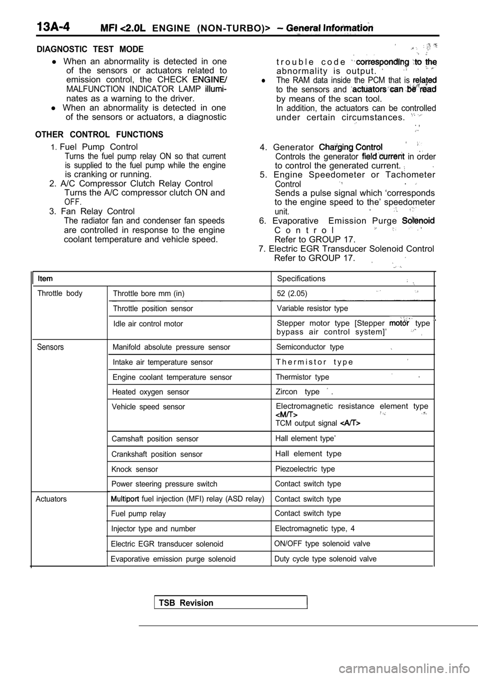
ENGINE (NON-TURBO)>
DIAGNOSTIC TEST MODE
l When an abnormality is detected in one
of the sensors or actuators related to
emission control, the CHECK
MALFUNCTION INDICATOR LAMP
nates as a warning to the driver.
l When an abnormality is detected in one
of the sensors or actuators, a diagnostic
OTHER CONTROL FUNCTIONS
t r o u b l e c o d e
a b n o r m a l i t y i s o u t p u t .
lThe RAM data inside the PCM that is
to the sensors and
by means of the scan tool.
In addition, the actuators can be controlled
under certain circumstances. . ,
1. Fuel Pump Control
Turns the fuel pump relay ON so that current
is supplied to the fuel pump while the engine
is cranking or running.
2. A/C Compressor Clutch Relay Control Turns the A/C compressor clutch ON and
OFF.
3. Fan Relay Control
The radiator fan and condenser fan speeds
are controlled in response to the engine
coolant temperature and vehicle speed. 4. Generator
Controls the generator in order
to control the generated current.
5. Engine Speedometer or Tachometer
Control.
Sends a pulse signal which ‘corresponds
to the engine speed to the’ speedometer
unit..
6. Evaporative Emission Purge
C o n t r o l
Refer to GROUP 17.
7. Electric EGR Transducer Solenoid Control Refer to GROUP 17.
Throttle body
Sensors
Actuators
Specifications
Throttle bore mm (in) 52 (2.05)
Throttle position sensor Variable resistor type
Idle air control motor
Stepper motor type [Stepper type
bypass air control system]’,
Manifold absolute pressure sensor Semiconductor type
Intake air temperature sensorT h e r m i s t o r t y p e
Engine coolant temperature sensorThermistor type .
Heated oxygen sensorZircon type .
Vehicle speed sensorElectromagnetic resistance element type
TCM output signal
Camshaft position sensor Hall element type’
Crankshaft position sensor
Hall element type
Knock sensor Piezoelectric type
Power steering pressure switch Contact switch type
fuel injection (MFI) relay (ASD relay)
Contact switch type
Fuel pump relay Contact switch type
Injector type and number Electromagnetic type, 4
Electric EGR transducer solenoid ON/OFF type solenoid valve
Evaporative emission purge solenoid Duty cycle type solenoid valve
TSB Revision
Page 385 of 2103
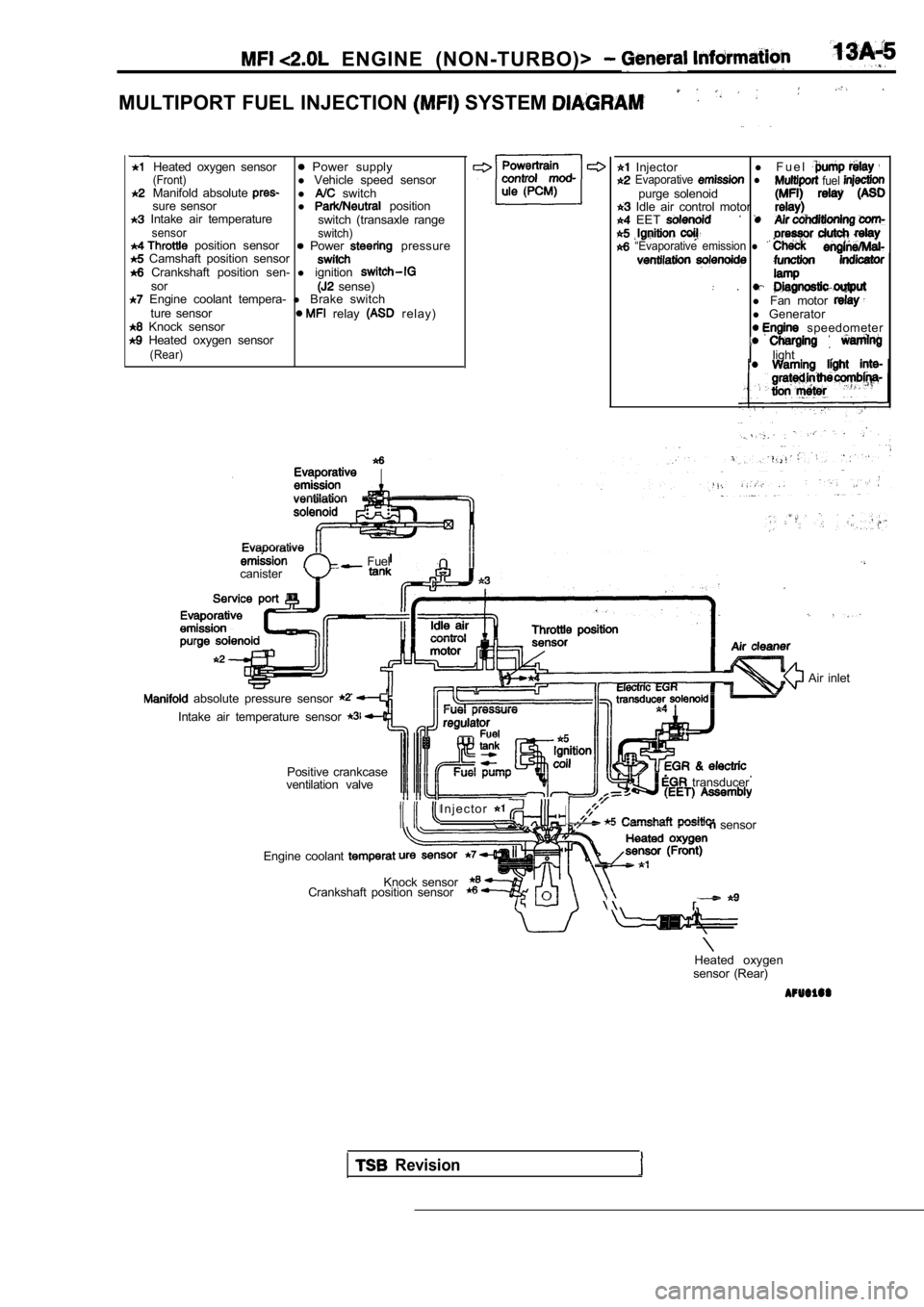
ENGINE (NON-TURBO)>
MULTIPORT FUEL INJECTION SYSTEM
Heated oxygen sensor Power supply(Front)l Vehicle speed sensor
Manifold absolute l switch
sure sensor l position Intake air temperature
switch (transaxle rangesensor switch) position sensor Power pressure Camshaft position sensor Crankshaft position sen- l ignitionsor sense) Engine coolant tempera- l Brake switch
ture sensor relay r e l a y ) Knock sensor Heated oxygen sensor(Rear)
Injector l
F u e l Evaporative l fuel purge solenoid Idle air control motor EET
“Evaporative emission l
.l Fan motor l Generator speedometer
light
.
Fuel
canister
absolute pressure sensor
Intake air temperature sensor
Positive crankcase
ventilation valve
I n j e c t o r
transducer
sensor
Engine coolant
Knock sensor
Crankshaft position sensor
Air inlet
Heated oxygen
sensor (Rear)
Revision
Page 389 of 2103
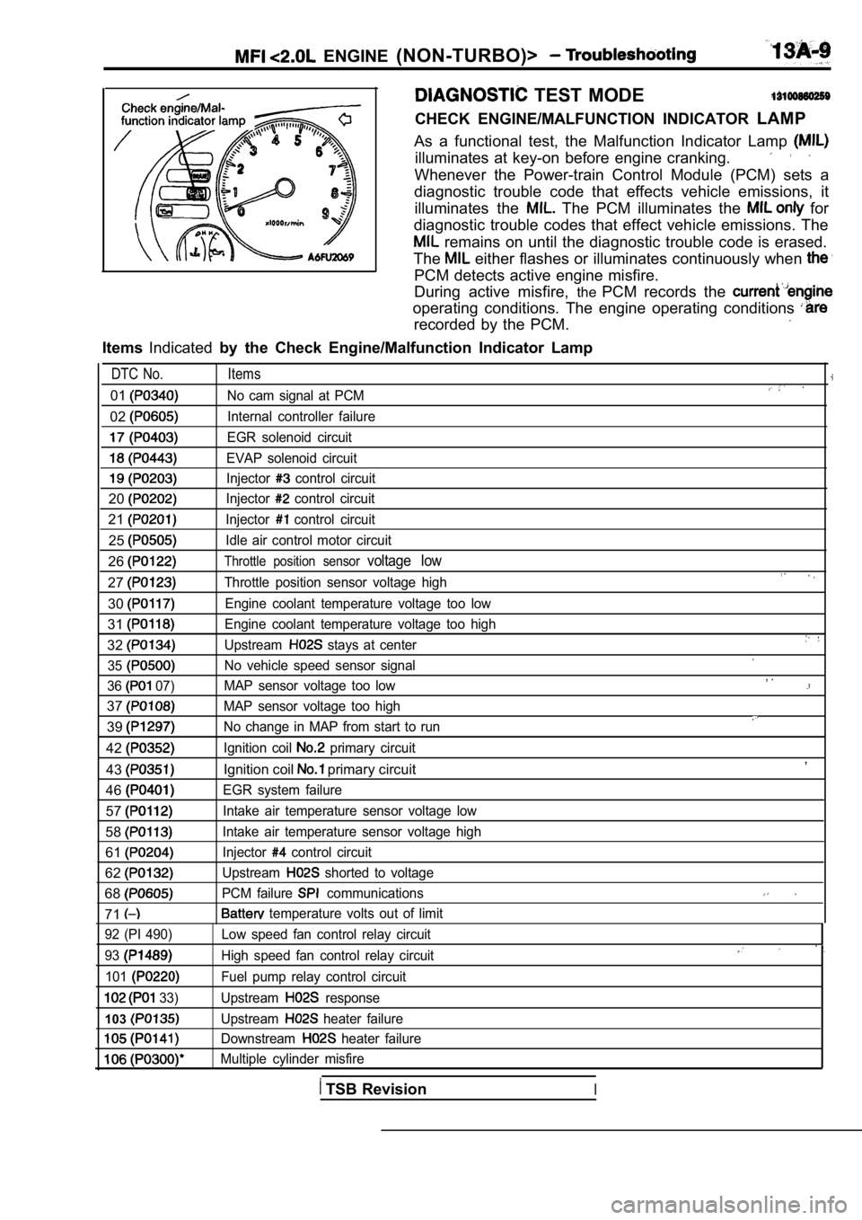
ENGINE (NON-TURBO)>
TEST MODE
CHECK ENGINE/MALFUNCTION INDICATOR LAMP
As a functional test, the Malfunction Indicator Lam p
illuminates at key-on before engine cranking.
Whenever the Power-train Control Module (PCM) sets a
diagnostic trouble code that effects vehicle emissi ons, it
illuminates the
The PCM illuminates the for
diagnostic trouble codes that effect vehicle emissi ons. The
remains on until the diagnostic trouble code is erased.
The
either flashes or illuminates continuously when
PCM detects active engine misfire.
During active misfire, thePCM records the
operating conditions. The engine operating conditio ns
recorded by the PCM.
ItemsIndicated by the Check Engine/Malfunction Indicator Lamp
DTC No. Items
01No cam signal at PCM
02Internal controller failure
EGR solenoid circuit
EVAP solenoid circuit
Injector control circuit
20Injector control circuit
21Injector control circuit
25Idle air control motor circuit
26Throttle position sensor voltage low
27Throttle position sensor voltage high
30Engine coolant temperature voltage too low
31Engine coolant temperature voltage too high
32Upstream stays at center
35
No vehicle speed sensor signal
36
07) MAP sensor voltage too low
37MAP sensor voltage too high
39No change in MAP from start to run
42Ignition coil primary circuit
43Ignition coil primary circuit
46
EGR system failure
57Intake air temperature sensor voltage low
58Intake air temperature sensor voltage high
61Injector control circuit
62Upstream shorted to voltage
68PCM failure communications
71 temperature volts out of limit
, .
,
92 (PI 490)
93
101
33)
103
Low speed fan control relay circuit
High speed fan control relay circuit
Fuel pump relay control circuit
Upstream
response
Upstream
heater failure
Downstream
heater failure
Multiple cylinder misfire
TSB RevisionI