1990 MITSUBISHI SPYDER coolant level
[x] Cancel search: coolant levelPage 38 of 2103
GENERAL Recommended Lubricants and Capacities
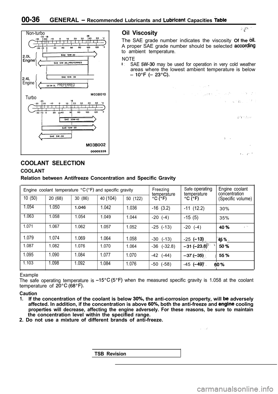
Non-turbo
I
EngineI PREFERRED
Turbo
Oil Viscosity
The SAE grade number indicates the viscosity Of the
A proper SAE grade number should be selected
to ambient temperature.
NOTE
l :SAE may be used for operation in very cold weather
areas where the lowest ambient temperature is below
COOLANT SELECTION
COOLANT
Relation between Antifreeze Concentration and Speci fic Gravity
Engine coolant temperature and specific gravity
10 (50)20 (68)30 (86)
40(104)50 (122)
1.054
1.0501.042
1.036
1.0631.058 1.0541.049
1.044
1.0711.0671.0621.0571.052 Freezing
Safe
operatingEngine coolant
temperature temperature concentration
(Specific volume)
-16 (3.2)
-11 (12.2)30%
-20 (-4)
-15 (5)35%
-25 (-13) -20 (-4)
1.079
1.074 1.0691.064
1.058-30 (-13)-25
1.0871.082 1.0761.070
1.064-36 (-32.8)
1.095 1.090 1.0841.077
1.070-42 (-44)
1.1031.0981.0921.0841.076-50 (-58)-45
Example
The safe operating temperature is when the measured specific gravity is 1.058 at the coolant
temperature of
Caution
1.If the concentration of the coolant is below the anti-corrosion property, will adversely
affected. In addition, if the concentration is abov e
both the anti-freeze and cooling
properties will decrease, affecting the engine adve rsely. For these reasons, be sure to maintain
the concentration level within the specified range.
2. Do not use a mixture of different brands of anti -freeze.
TSB Revision
Page 50 of 2103
GENERAL Maintenance Service
,
Revision
Drain Plug
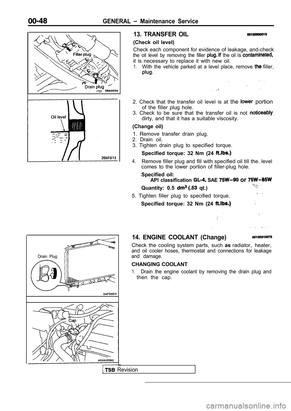
13. TRANSFER OIL
(Check oil level)
Check each component for evidence of leakage, and-check
the oil level by removing the filler the oil is
it is necessary to replace it with new oil.
1.With the vehicle parked at a level place, remove filler,
2. Check that the transfer oil level is at the portion
of the filler plug hole.
3. Check to be sure that the transfer oil is not
dirty, and that it has a suitable viscosity.
(Change oil) 1. Remove transfer drain plug.
2. Drain oil.
3. Tighten drain plug to specified torque.
Specified torque: 32 Nm (24
4.Remove filler plug and fill with specified oil till the. level
comes to the lower portion of filler-plug hole.
Specified oil:
API classification SAE or
Quantity: 0.5 qt.)
5. Tighten filler plug to specified torque.
Specified torque: 32 Nm (24
14. ENGINE COOLANT (Change)
Check the cooling system parts, such asradiator, heater,
and oil cooler hoses, thermostat and connections fo r leakage
and damage.
CHANGING COOLANT
1.Drain the engine coolant by removing the drain plug and
then the cap.
Page 51 of 2103
GENERAL Maintenance
a
Engine (Non-turbo)>
in plug
Engine>
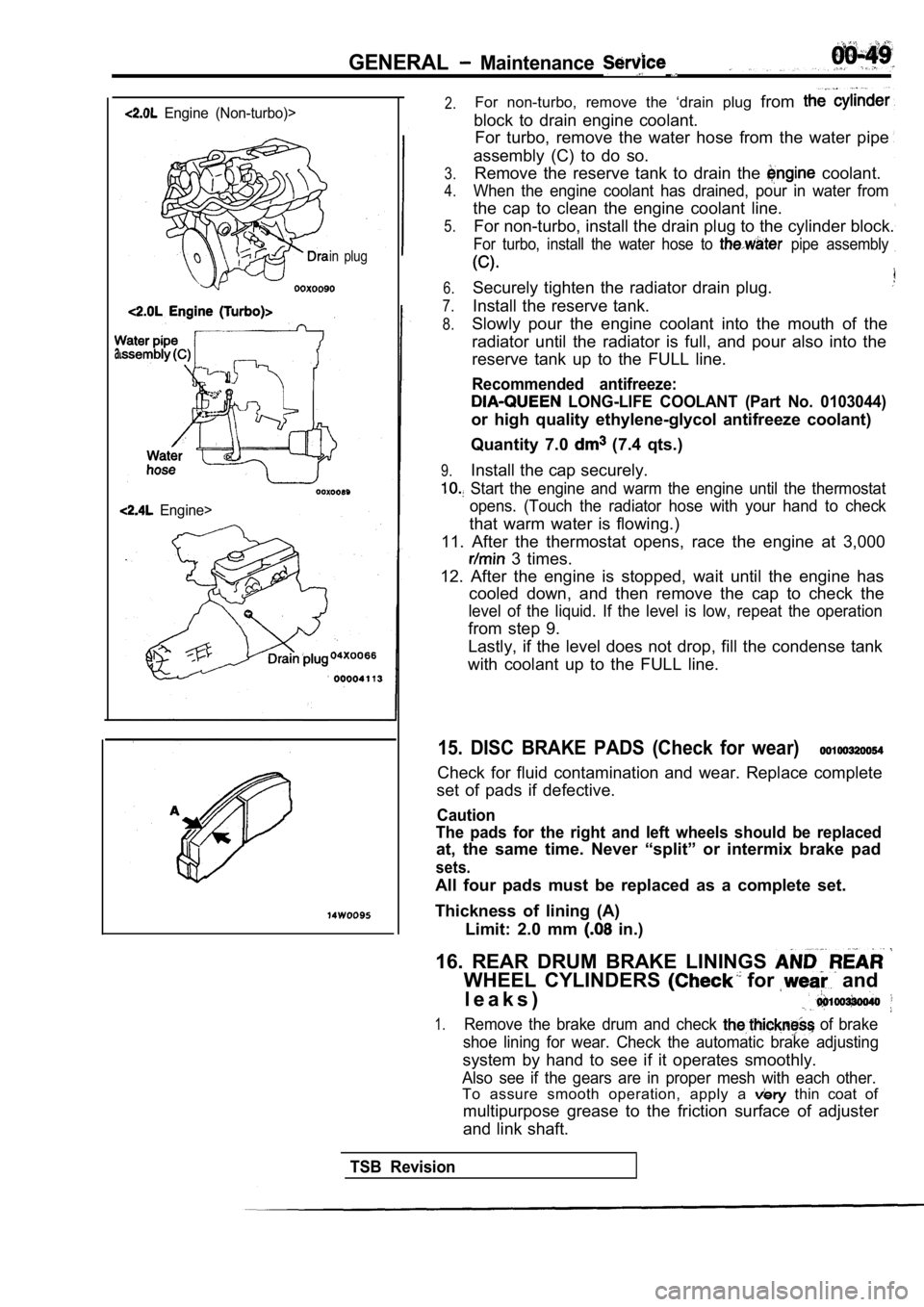
2.For non-turbo, remove the ‘drain plug from
block to drain engine coolant.
For turbo, remove the water hose from the water pip e
assembly (C) to do so.
3.
4.
5.Remove the reserve tank to drain the coolant.
When the engine coolant has drained, pour in water from
the cap to clean the engine coolant line.
For non-turbo, install the drain plug to the cylind er block.
For turbo, install the water hose to pipe assembly
6.
7.
8.
Securely tighten the radiator drain plug.
Install the reserve tank.
9.
Slowly pour the engine coolant into the mouth of th e
radiator until the radiator is full, and pour also into the
reserve tank up to the FULL line.
Recommended antifreeze:
LONG-LIFE COOLANT (Part No. 0103044)
or high quality ethylene-glycol antifreeze coolant)
Quantity 7.0
(7.4 qts.)
Install the cap securely.
Start the engine and warm the engine until the the rmostat
opens. (Touch the radiator hose with your hand to c heck
that warm water is flowing.)
11. After the thermostat opens, race the engine at 3,000
3 times.
12. After the engine is stopped, wait until the eng ine has
cooled down, and then remove the cap to check the
level of the liquid. If the level is low, repeat th e operation
from step 9.
Lastly, if the level does not drop, fill the conden se tank
with coolant up to the FULL line.
15. DISC BRAKE PADS (Check for wear)
Check for fluid contamination and wear. Replace com plete
set of pads if defective.
Caution
The pads for the right and left wheels should be re placed
at, the same time. Never “split” or intermix brake pad
sets.
All four pads must be replaced as a complete set.
Thickness of lining (A) Limit: 2.0 mm
in.)
16. REAR DRUM BRAKE LININGS
WHEEL CYLINDERS for and
l e a k s )
1.Remove the brake drum and check of brake
shoe lining for wear. Check the automatic brake adj usting
system by hand to see if it operates smoothly.
Also see if the gears are in proper mesh with each other.
To assure smooth operation, apply a thin coat of
multipurpose grease to the friction surface of adju ster
and link shaft.
TSB Revision
Page 183 of 2103
ENGINE On-vehicle.’
M A N I F O L D V A C U U M
1.Before inspection, set vehicles. in the condition:
Engine coolant
lLights, electric cooling and
lTransaxle: Neutral (P
2. Connect the scan tool to the data link connector.
,
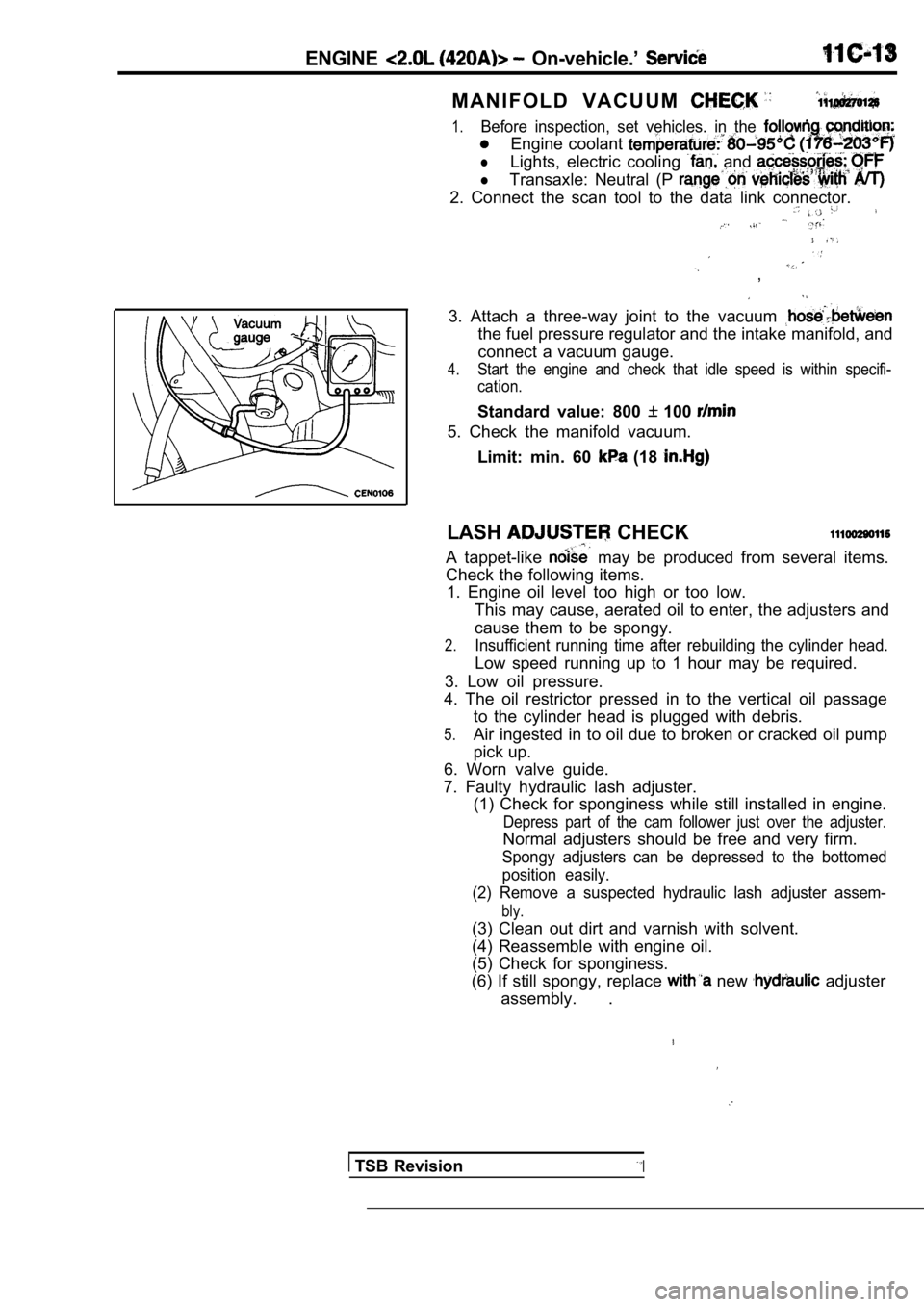
3. Attach a three-way joint to the vacuum
the fuel pressure regulator and the intake manifold, and
connect a vacuum gauge.
4.Start the engine and check that idle speed is withi n specifi-
cation.
Standard value: 800 100
5. Check the manifold vacuum.
Limit: min. 60
(18
LASH CHECK
A tappet-like may be produced from several items.
Check the following items. 1. Engine oil level too high or too low.
This may cause, aerated oil to enter, the adjusters and
cause them to be spongy.
2.Insufficient running time after rebuilding the cyli nder head.
Low speed running up to 1 hour may be required.
3. Low oil pressure.
4. The oil restrictor pressed in to the vertical oi l passage
to the cylinder head is plugged with debris.
5.Air ingested in to oil due to broken or cracked oil pump
pick up.
6. Worn valve guide.
7. Faulty hydraulic lash adjuster. (1) Check for sponginess while still installed in e ngine.
Depress part of the cam follower just over the adju ster.
Normal adjusters should be free and very firm.
Spongy adjusters can be depressed to the bottomed
position easily.
(2) Remove a suspected hydraulic lash adjuster asse m-
bly.
(3) Clean out dirt and varnish with solvent.
(4) Reassemble with engine oil.
(5) Check for sponginess.
(6) If still spongy, replace
new adjuster
assembly. .
TSB RevisionI
Page 227 of 2103
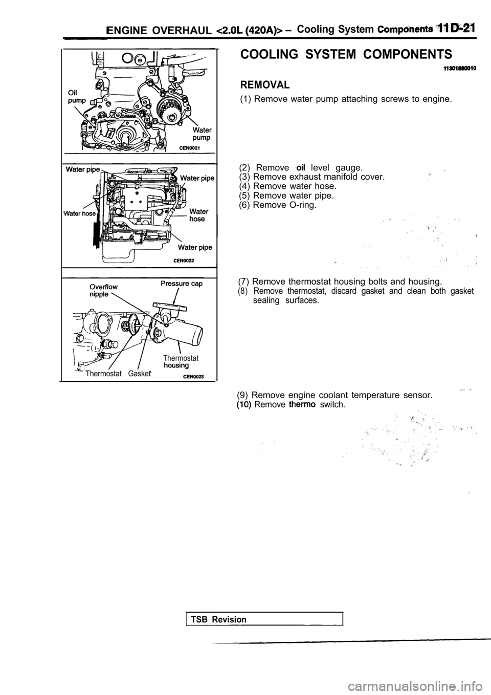
ENGINE OVERHAUL Cooling System
COOLING SYSTEM COMPONENTS
REMOVAL
(1) Remove water pump attaching screws to engine.
Thermostat
Thermostat Gasket
(2) Remove level gauge.
(3) Remove exhaust manifold cover.
(4) Remove water hose.
(5) Remove water pipe.
(6) Remove O-ring.
(7) Remove thermostat housing bolts and housing.
(8)Remove thermostat, discard gasket and clean both ga sket
sealing surfaces.
(9) Remove engine coolant temperature sensor.
Remove switch.
TSB Revision
Page 228 of 2103
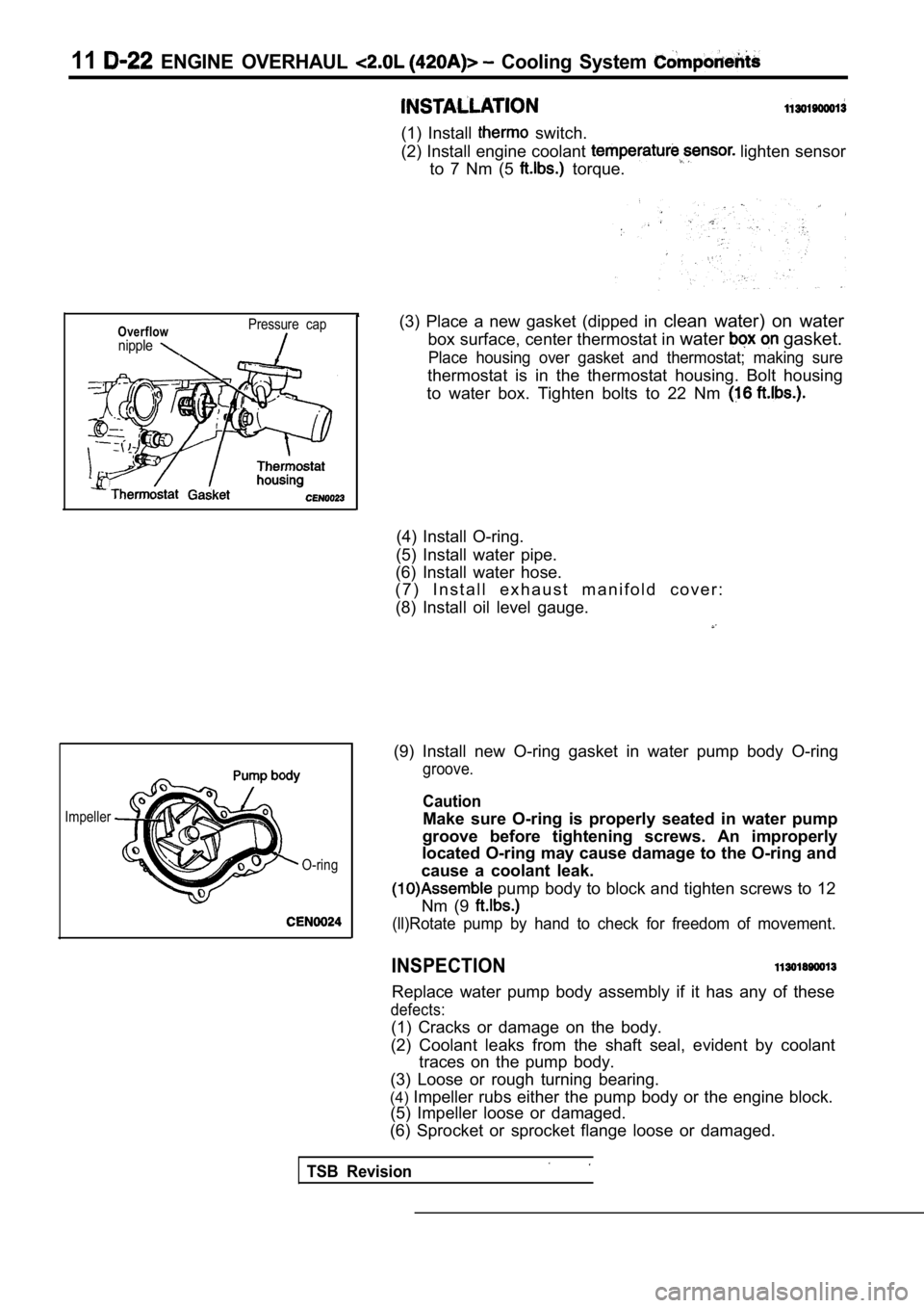
11 ENGINE OVERHAUL Cooling System
(1) Install switch.
(2) Install engine coolant
lighten sensor
to 7 Nm (5
torque.
Overflownipple
Pressure cap
Impeller
TSB Revision
O-ring
(3) Place a new gasket (dipped in clean water) on water
box surface, center thermostat in water
gasket.
Place housing over gasket and thermostat; making su re
thermostat is in the thermostat housing. Bolt housing
to water box. Tighten bolts to 22 Nm
(4) Install O-ring.
(5) Install water pipe.
(6) Install water hose.
( 7 ) I n s t a l l e x h a u s t m a n i f o l d c o v e r :
(8) Install oil level gauge.
(9) Install new O-ring gasket in water pump body O- ring
groove.
Caution
Make sure O-ring is properly seated in water pump
groove before tightening screws. An improperly
located O-ring may cause damage to the O-ring and
cause a coolant leak.
pump body to block and tighten screws to 12
Nm (9
(ll)Rotate pump by hand to check for freedom of mov ement.
INSPECTION
Replace water pump body assembly if it has any of these
defects:
(1) Cracks or damage on the body.
(2) Coolant leaks from the shaft seal, evident by c oolant
traces on the pump body.
(3) Loose or rough turning bearing.
(4) Impeller rubs either the pump body or the engine bl ock.
(5) Impeller loose or damaged.
(6) Sprocket or sprocket flange loose or damaged.
Page 459 of 2103
![MITSUBISHI SPYDER 1990 Service Repair Manual ,
-- Scan tool 156,I
C o d e G e n e r a l s c a n t o o l D o w n s t r e a m to
No. G r o u n d
21
[Comment]l Downstream heated oxygen Backgroundl harness and connectors lWhen MITSUBISHI SPYDER 1990 Service Repair Manual ,
-- Scan tool 156,I
C o d e G e n e r a l s c a n t o o l D o w n s t r e a m to
No. G r o u n d
21
[Comment]l Downstream heated oxygen Backgroundl harness and connectors lWhen](/manual-img/19/57345/w960_57345-458.png)
,
-- Scan tool 156,I
C o d e G e n e r a l s c a n t o o l D o w n s t r e a m to
No. G r o u n d
21
[Comment]l Downstream heated oxygen Backgroundl harness and connectors lWhen the heated oxygen sensor temperature is low, t he sensor has the same electrical
l PCM failed characteristics as an insulator.lThe heated oxygen sensor output signal line is That is is approx. when the heated oxygen sensor temperature is low.If the heated oxygen sensor output signal line is g rounded, will become lRange of checkl Engine coolant temperature when the engine starts: or lessl Within three seconds after the engine starts
Set Conditions
The heated oxygen sensor output signal line is
or less.
NGCheck the harness I .oxygen sensor connector.. , ,
OK
Replace the PCM.
11
[Comment]Background , connectedlAfter the engine has been started, the PCM maintain s an expected camshaft port l position
Scan tool 157,General scan toolIntermittent Loss of CMP CKP Probable cause
value. connectedlAt every crankshaft leading edge, this value is updated to reflect the expected
.Camshaft position sensor change in the cam level.
l lAt every crankshaft trailing edge, this value is compared to the true port level. sensor improperly lIf there is a disagreement between two values, then the diagnostic code isset.l sensor
Range of Check
l Engine: running
Set Condition
l Cam and crank signals have been out of sync, than times.
N GCheck the following connectors:. A-l 06
OK
__Check no cam sync. signal at PCM. (Refer to INSPECTION PROCEDURE FOR DIAGNOSTIC TROUBLE
CODE.
Check no crank reference signal at PCM. (Refer to INSPECTION PROCEDURE FOR DIAGNOSTIC TROUBLE
TSB Revision
Page 528 of 2103
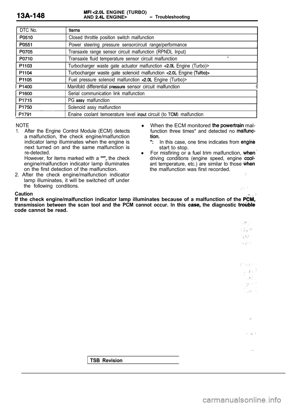
ENGINE (TURBO)
AND
ENGINE> Troubleshooting
DTC No.
Closed throttle position switch malfunction
Power steering pressure sensorcircuit range/perfor mance
Transaxle range sensor circuit malfunction (RPNDL Input)
Transaxle fluid temperature sensor circuit malfunct ion
Turbocharger waste gate actuator malfunction Engine (Turbo)>
Turbocharger waste gate solenoid malfunction Engine
Fuel pressure solenoid malfunction Engine (Turbo)>
Manifold differential sensor circuit malfunction
Serial communication link malfunction
PG
malfunction
Solenoid assy malfunction
Enaine coolant temoerature level
circuit (to malfunction
NOTElWhen the ECM monitored mal-
1.After the Engine Control Module (ECM) detects function three times* and detected no
a malfunction, the check engine/malfunction
indicator lamp illuminates when the engine isIn this case, one time indicates from
next turned on and the same malfunction is
start to stop.
re-detected.lFor misfiring or a fuel trim malfunction,
However, for items marked with a the checkdriving conditions (engine speed, engine
engine/malfunction indicator lamp illuminatesant temperature, etc.) are similar to those
on the first detection of the malfunction. the malfunction was first recorded.
2. After the check engine/malfunction indicator
lamp illuminates, it will be switched off under
the following conditions.
Caution,
If the check engine/malfunction indicator lamp illu minates because of a malfunction of the
transmission between the scan tool and the PCM cann ot occur. In this the diagnostic
code cannot be read.
TSB Revision