Page 108 of 2103
![MITSUBISHI SPYDER 1990 Service Repair Manual ENGINE OVERHAUL
Items Standard value
Piston ring end gap mm (in.)
Piston pin O.D. mm (in.)
0 . 8
Oil 9 . 8
21
Piston pin press-in load (Ibs.)
[Room temperature]
Crankshaft pin MITSUBISHI SPYDER 1990 Service Repair Manual ENGINE OVERHAUL
Items Standard value
Piston ring end gap mm (in.)
Piston pin O.D. mm (in.)
0 . 8
Oil 9 . 8
21
Piston pin press-in load (Ibs.)
[Room temperature]
Crankshaft pin](/manual-img/19/57345/w960_57345-107.png)
ENGINE OVERHAUL
Items Standard value
Piston ring end gap mm (in.)
Piston pin O.D. mm (in.)
0 . 8
Oil 9 . 8
21
Piston pin press-in load (Ibs.)
[Room temperature]
Crankshaft pin oil clearance mm (in.) 17,500
Connecting rod big end side clearance mm (in.)
Crankshaft, flywheel and drive plate
Bearing cap bolt shank length mm (in.)
0 . 4
Crankshaft end play mm (in.)
Crankshaft journal O.D. mm (in.) 0 . 2 5
57 (2.24)
pin O.D. mm (in.) 42 (1.77)
Crankshaft journal oil clearance mm (in.)
to cylinder clearance mm (in.)
0 . 1
block flatness of gasket surface mm (in.) 0.05 0.1
block grinding limit of gasket surface mm (in.)l 0.2‘Total resurfacing depth of both cylinder head and cylinder block
block overall height mm (in.)283.9-284.1
(11.177-11.185)
block I.D. mm (in.) 85.0 (3.35)
TSBRevision
REWORK DIMENSIONS
Items
Cylinder head and valve
Oversize rework dimensions of valve guide0.05 O.S.
hole (both intake and exhaust) mm (in.) 0.25 O.S.
0.50
Intake oversize rework 0.3
dimensions of valve seat hole mm (in.)
0.6 O.S.
Exhaust oversize rework dimensions of valve 0.3 O.S.
seat hole
mm (in.)0.6 O.S.
Crankshaft, flywheel and drive plate
Crankshaft out of roundness and taper of journal an d pin mm (in.)
Standard value
12.25-12.27 ,
,
Max. 0.01
NOTE
O.D.: Outer diameter
I.D.: Inner diameter
Oversize diameter
Page 168 of 2103

ENGINE OVERHAUL and Drive Plate
, Flywheel
Thrustdirection
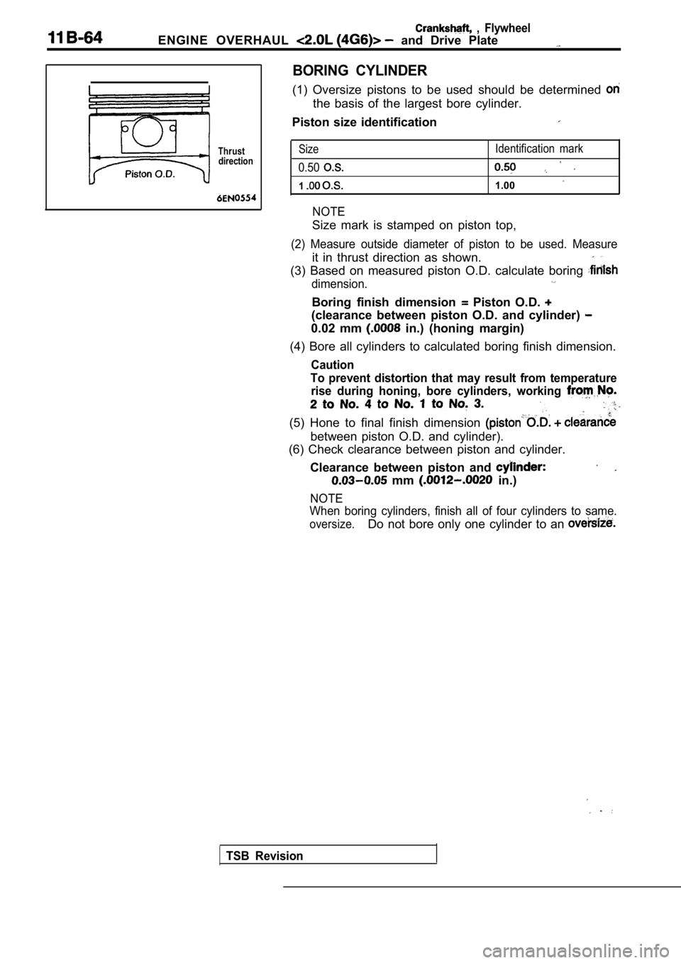
BORING CYLINDER
(1) Oversize pistons to be used should be determine d
the basis of the largest bore cylinder.
Piston size identification
Size
0.50
1
NOTE
Identification mark
1.00
Size mark is stamped on piston top,
(2) Measure outside diameter of piston to be used. Measure
it in thrust direction as shown.
(3) Based on measured piston O.D. calculate boring
dimension.
Boring finish dimension Piston O.D.
(clearance between piston O.D. and cylinder)
0.02 mm in.) (honing margin)
(4) Bore all cylinders to calculated boring finish dimension.
Caution
To prevent distortion that may result from temperat ure
rise during honing, bore cylinders, working
(5) Hone to final finish dimension
between piston O.D. and cylinder).
(6) Check clearance between piston and cylinder.
Clearance between piston and
mm in.)
NOTE
When boring cylinders, finish all of four cylinders to same.
oversize.Do not bore only one cylinder to an
TSB Revision
Page 371 of 2103

ENGINE OVERHAUL Crankshaft, Flywheel and, . .
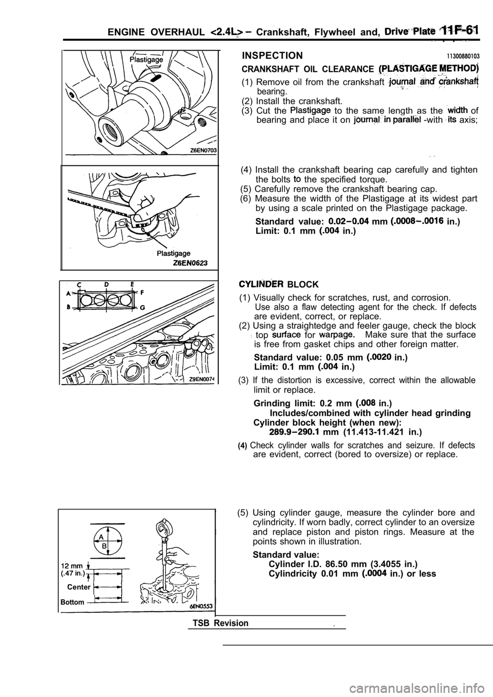
INSPECTION11300880103
CRANKSHAFT OIL CLEARANCE
(1) Remove oil from the crankshaft
bearing.
(2) Install the crankshaft.
(3) Cut the
to the same length as the of
bearing and place it on
-with axis;
(4) Install the crankshaft bearing cap carefully an d tighten
the bolts
the specified torque.
(5) Carefully remove the crankshaft bearing cap.
(6) Measure the width of the Plastigage at its wide st part
by using a scale printed on the Plastigage package.
Standard value:
mm in.)
Limit: 0.1 mm
in.)
BLOCK
(1) Visually check for scratches, rust, and corrosi on.
Use also a flaw detecting agent for the check. If d efects
are evident, correct, or replace.
(2) Using a straightedge and feeler gauge, check th e block
top for Make sure that the surface
is free from gasket chips and other foreign matter.
Standard value: 0.05 mm
in.)
Limit: 0.1 mm
in.)
(3) If the distortion is excessive, correct within the allowable
limit or replace.
Grinding limit: 0.2 mm
in.)
Includes/combined with cylinder head grinding
Cylinder block height (when new):
mm (11.413-11.421 in.)
(4)Check cylinder walls for scratches and seizure. If defects
are evident, correct (bored to oversize) or replace.
Center
Bottom
TSB Revision
(5) Using cylinder gauge, measure the cylinder bore and
cylindricity. If worn badly, correct cylinder to an oversize
and replace piston and piston rings. Measure at the
points shown in illustration.
Standard value: Cylinder I.D. 86.50 mm (3.4055 in.)
Cylindricity 0.01 mm
in.) or less
Page 372 of 2103
ENGINE OVERHAUL Crankshaft, Flywheel ‘and ‘Drive Plate
Thrustdirection
B O R I N G C Y L I N D E R
(1) Oversize pistons to be used should determined on
the basis of the largest bore
Piston size identification
Size mark
0.50
1
NOTE
Size mark is stamped on piston top.
(2)
outside diameter of piston to be used.
it in thrust direction as shown.
(3) Based on measured piston O.D. calculate boring
Boring finish dimension
between piston O.D.
0.02 mm in.) (honing margin)
(4) Bore all cylinders to calculated boring finish dimension.
Caution
To prevent distortion that may result from temperat ure
rise during honing, bore cylinders, working from
2to No. 4 to No. 1 to No. 3.
(5) Hone to final finish dimension
clearance
between piston O.D. and cylinder).
(6) Check clearance between- piston and cylinder.
Clearance between piston and cylinder:
mm in.)
NOTE
When boring cylinders, finish all of four cylinders to same
Do not bore only one cylinder to an
TSB Revision
Page 1586 of 2103

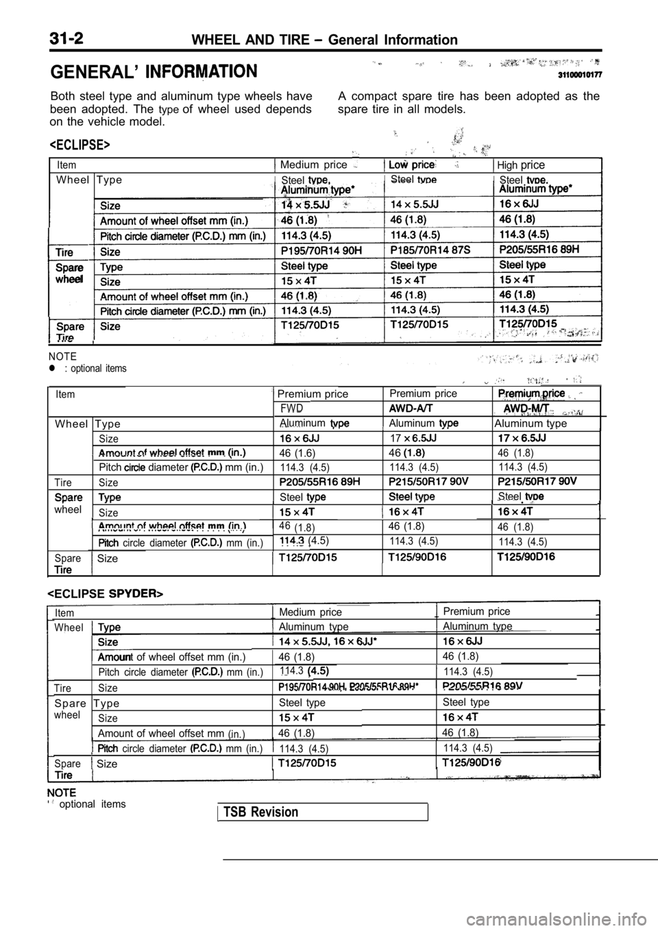
WHEEL AND TIRE General Information
GENERAL’
Both steel type and aluminum type wheels have
been adopted. The typeof wheel used depends
on the vehicle model.
Item
W h e e l T y p e A compact spare tire has been adopted as the
spare tire in all models.
Medium price
ISteel
High price
ISteelISteel
Tire
Spare
wheel
NOTE
l : optional items
Item
FWD
W h e e l T y p e
Size
Premium price
.
Aluminum
Premium price
AluminumAluminum type
17
mm 46 (1.6)4646 (1.8)
Pitch diameter mm (in.)114.3 (4.5) 114.3 (4.5)114.3 (4.5)
Tire Size
SteelSteel l .wheelSize
. . . . . . .
circle diameter mm (in.)
mm46 (1.8)46 (1.8)46 (1.8)
(4.5)114.3 (4.5) 114.3 (4.5)
Spare
Size
ItemMedium price Premium price
WheelAluminum type
Aluminum type
Size
Amount of wheel offset mm (in.)
Pitch circle diameter mm (in.)
46 (1.8)46 (1.8)
114.3 ,114.3 (4.5)
Tire Size
. . .
Steel type
46 (1.8)
S p a r e T y p eSteel type
wheel
Size
Amount of wheel offset mm(in.)46 (1.8)
circle diameter mm (in.) 114.3 (4.5) 114.3 (4.5)
Spare
Size
l .optional items TSB Revision