1990 MITSUBISHI SPYDER tow
[x] Cancel search: towPage 3 of 2103
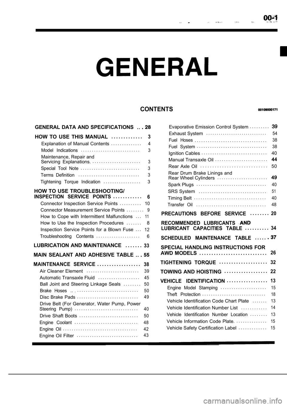
CONTENTS
GENERAL DATA AND SPECIFICATIONS. .
HOW TO USE THIS MANUAL. . . . . . . . . . . . .3
Explanation of Manual Contents. . . . . . . . . . . . . .4
Model Indications
. . . . . . . . . . . . . . . . . . . . . . . . . . .3
Maintenance, Repair and
Servicing Explanations. . . . . . . . . . . . . . . . . . . . . . .
3
Special Tool Note. . . . . . . . . . . . . . . . . . . . . . . . . . .3
Terms Definition. . . . . . . . . . . . . . . . . . . . . . . . . . . .3
Tightening Torque Indication. . . . . . . . . . . . . . . . .3
HOW TO USE TROUBLESHOOTING/
INSPECTION SERVICE POINTS. . . . . . . . . . . .6
Connector Inspection Service Points
. . . . . . . . . .10
Connector Measurement Service Points . . . . . . . .9
How to Cope with Intermittent Malfunctions . . .11
How to Use the Inspection Procedures
. . . . . . .
8
Inspection Service Points for a Blown Fuse . . .
12
Troubleshooting Contents. . . . . . . . . . . . . . . . . . . .6
LUBRICATION AND MAINTENANCE . . . . . . .33
MAIN SEALANT AND ADHESIVE TABLE
. .
MAINTENANCE SERVICE. . . . . . . . . . . . . . . . . .38
Air Cleaner Element. . . . . . . . . . . . . . . . . . . . . . . .39
Automatic Transaxle Fluid
. . . . . . . . . . . . . . . . . . .45
Ball Joint and Steering Linkage Seals
. . . . . . . .50
Brake Hoses.... . . . . . . . . . . . . . . . . . . . . . . . . . . .50
Disc Brake Pads. . . . . . . . . . . . . . . . . . . . . . . . . . . .49
Drive Belt (For Generator, Water Pump, Power
Steering Pump). . . . . . . . . . . . . . . . . . . . . . . . . . . . .40
Drive Shaft Boots
. . . . . . . . . . . . . . . . . . . . . . . . . . .50
Engine Coolant. . . . . . . . . . . . . . . . . . . . . . . . . . . . .48
Engine Oil. . . . . . . . . . . . . . . . . . . . . . . . . . . . . . . . . .42
Engine Oil Filter. . . . . . . . . . . . . . . . . . . . . . . . . . . .43
Evaporative Emission Control System . . . . . . . . .
Exhaust System. . . . . . . . . . . . . . . . . . . . . . . . . . . . .54
Fuel Hoses. . . . . . . . . . . . . . . . . . . . . . . . . . . . . . . . .38
Fuel System. . . . . . . . . . . . . . . . . . . . . . . . . . . . . . . .38
Ignition Cables. . . . . . . . . . . . . . . . . . . . . . . . . . . . . .
40
Manual Transaxle Oil . . . . . . . . . . . . . . . . . . . . . . . .
Rear Axle Oil. . . . . . . . . . . . . . . . . . . . . . . . . . . .
50
Rear Drum Brake Linings and
Rear Wheel Cylinders . . . . . . . . . . . . . . . . . . . . . . .
Spark Plugs. . . . . . . . . . . . . . . . . . . . . . . . . . . . . . . .40
SRS System . . . . . . . . . . . . . . . . . . . . . . . . . . . . . . .51
Timing Belt. . . . . . . . . . . . . . . . . . . . . . . . . . . . . . . . .40
Transfer Oil. . . . . . . . . . . . . . . . . . . . . . . . . . . . . . . .48
PRECAUTIONS BEFORE SERVICE. . . . . . . .20
RECOMMENDED LUBRICANTS
LUBRICANT CAPACITIES TABLE. . . . . . . . . .34
SCHEDULED MAINTENANCE TABLE. . . . .
SPECIAL HANDLING INSTRUCTIONS FOR
AWD MODELS . . . . . . . . . . . . . . . . . . . . . . . . . . . .
26
TIGHTENING TORQUE. . . . . . . . . . . . . . . . . . . .32
TOWING AND HOISTING . . . . . . . . . . . . . . . . . .22
VEHICLE IDENTIFICATION. . . . . . . . . . . . . . . . .13
Engine Model Stamping. . . . . . . . . . . . . . . . . . . . .15
Theft Protection. . . . . . . . . . . . . . . . . . . . . . . . . . . . .18
Vehicle Identification Code Chart Plate
. . . . . . .13
Vehicle Identification Number List. . . . . . . . . . . .14
Vehicle Identification Number Location. . . . . . . .13
Vehicle Information Code Plate.. . . . . . . . . . . . . .15
Vehicle Safety Certification Label
. . . . . . . . . . . . .15
Page 24 of 2103
GENERAL Towing and Hoisting
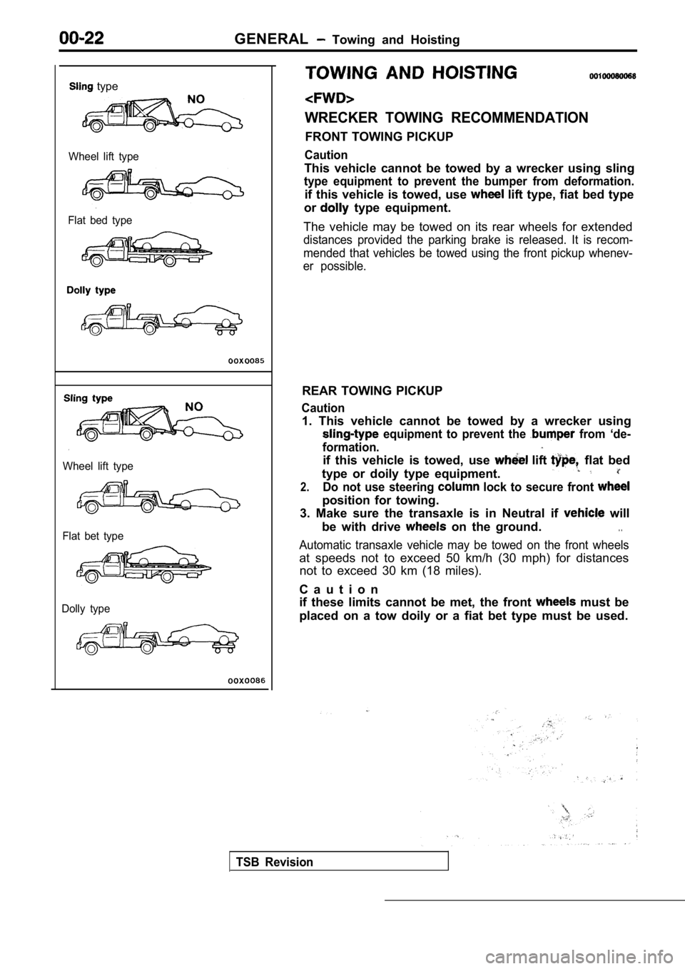
type
Wheel lift type
Flat bed type
Wheel lift type
Flat bet type
Dolly type
WRECKER TOWING RECOMMENDATION
FRONT TOWING PICKUP
Caution
This vehicle cannot be towed by a wrecker using sli ng
type equipment to prevent the bumper from deformati on.
if this vehicle is towed, use lift type, fiat bed type
or
type equipment.
The vehicle may be towed on its rear wheels for ext ended
distances provided the parking brake is released. It is recom-
mended that vehicles be towed using the front picku p whenev-
er possible.
REAR TOWING PICKUP
Caution
1. This vehicle cannot be towed by a wrecker using
equipment to prevent the from ‘de-
formation.
if this vehicle is towed, use lift flat bed
type or doily type equipment.
2.Do not use steering lock to secure front
position for towing.
3. Make sure the transaxle is in Neutral if
will
be with drive
on the ground.. .
Automatic transaxle vehicle may be towed on the fro nt wheels
at speeds not to exceed 50 km/h (30 mph) for distan ces
not to exceed 30 km (18 miles).
C a u t i o n
if these limits cannot be met, the front
must be
placed on a tow doily or a fiat bet type must be us ed.
TSB Revision
Page 25 of 2103
GENERAL Towing and Hoisting
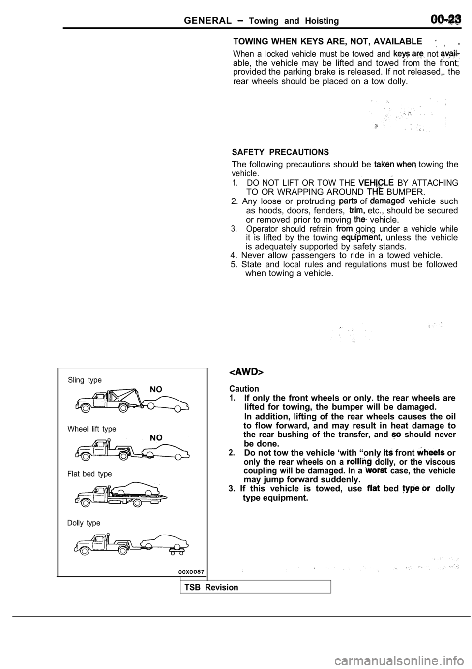
Sling type
Wheel lift type
Flat bed type
Dolly type
TOWING WHEN KEYS ARE, NOT, AVAILABLE .
When a locked vehicle must be towed and not
able, the vehicle may be lifted and towed from the front;
provided the parking brake is released. If not rele ased,. the
rear wheels should be placed on a tow dolly.
SAFETY PRECAUTIONS
The following precautions should be towing the
vehicle.
1.DO NOT LIFT OR TOW THE BY ATTACHING
TO OR WRAPPING AROUND BUMPER.
2. Any loose or protruding
of vehicle such
as hoods, doors, fenders,
etc., should be secured
or removed prior to moving
vehicle.
3.Operator should refrain going under a vehicle while
it is lifted by the towing unless the vehicle
is adequately supported by safety stands.
4. Never allow passengers to ride in a towed vehicl e.
5. State and local rules and regulations must be fo llowed
when towing a vehicle.
Caution
1.If only the front wheels or only. the rear wheels a re
lifted for towing, the bumper will be damaged.
In addition, lifting of the rear wheels causes the oil
to flow forward, and may result in heat damage to
the rear bushing of the transfer, and should never
be done.
2.Do not tow the vehicle ‘with “only front or
only the rear wheels on a dolly, or the viscous
coupling will be damaged. In a
case, the vehicle
may jump forward suddenly.
3. If this vehicle is towed, use
bed dolly
type equipment.
TSB Revision
Page 26 of 2103
GENERAL Towing and Hoisting. .
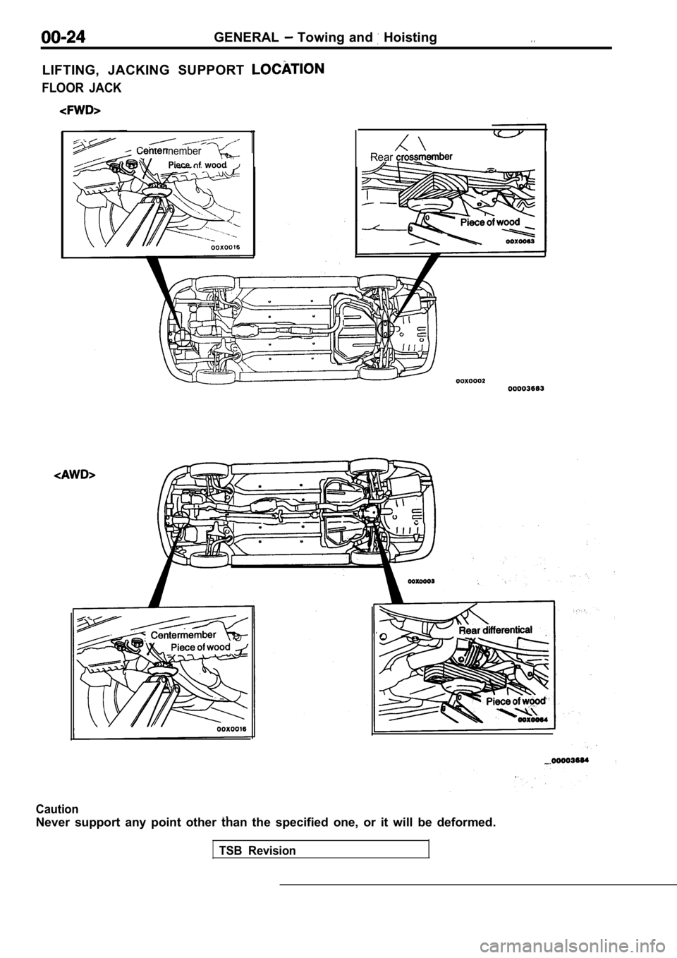
LIFTING, JACKING SUPPORT
FLOOR JACK
nember
Piece wood
1Rear
Caution
Never support any point other than the specified one, or it will be deformed.
TSB Revision
Page 40 of 2103
GENERAL Scheduled Maintenance Table/Maintenance Service
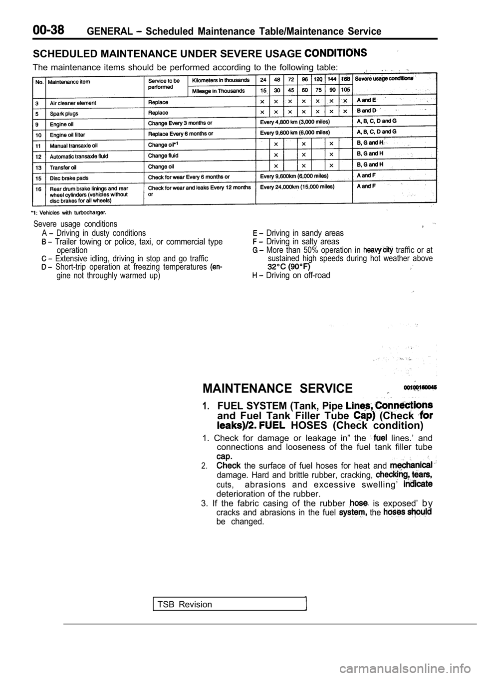
SCHEDULED MAINTENANCE UNDER SEVERE USAGE
The maintenance items should be performed according to the following table:
Severe usage conditions
A
Driving in dusty conditions
Trailer towing or police, taxi, or commercial type
operation
Extensive idling, driving in stop and go traffic
Short-trip operation at freezing temperatures
gine not throughly warmed up)
,
Driving in sandy areas
Driving in salty areas
More than 50% operation in traffic or at
sustained high speeds during hot weather above
Driving on off-road
MAINTENANCE SERVICE
1.FUEL SYSTEM (Tank, Pipe
and Fuel Tank Filler Tube (Check
HOSES (Check condition)
1. Check for damage or leakage in” the
lines.’ and
connections and looseness of the fuel tank filler t ube
2. the surface of fuel hoses for heat and
damage. Hard and brittle rubber, cracking,
cuts,abrasions and excessive swelling’
deterioration of the rubber.
3. If the fabric casing of the rubber
is exposed’ b y
cracks and abrasions in the fuel the
be changed.
TSB Revision
Page 47 of 2103
GENERAL Maintenance, Service
5. Tighten filler plug to specified torque.
Specified torque:
Engine (Non-turbo)>30 Nm (22
Engine (Turbo) and Engine>
32 Nm (24
12. AUTOMATIC TRANSAXLE FLUID
(Check ‘fluid level)
Engine (Non-turbo)>
1. Position the vehicle on a level surface.
2. Start engine and allow to idle in PARK for at le ast 60
seconds. The warmer the transaxle fluid, the more
accurate the reading.
3.While sitting in driver seat, apply brakes and plac e gear
selector in each position. Return gear selector to PARK.
4. Raise hood and remove transaxle fluid level indi cator
(dipstick) and wipe clean with a suitable shop towe l.
5.
dipstick and verify it is seated in fill tube.
Caution
Do not overfill automatic transaxle, leakage or dam age
can result.
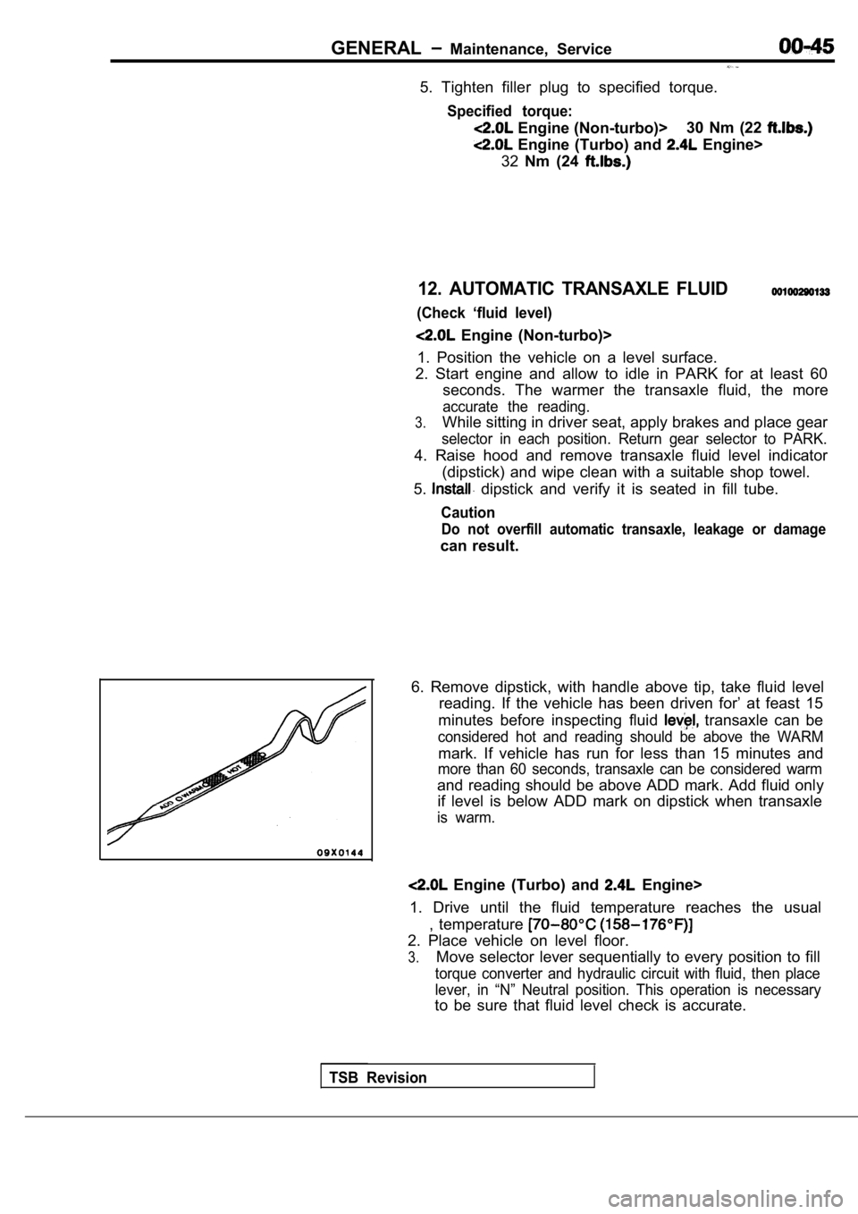
6. Remove dipstick, with handle above tip, take flu id level
reading. If the vehicle has been driven for’ at fea st 15
minutes before inspecting fluid
transaxle can be
considered hot and reading should be above the WARM
mark. If vehicle has run for less than 15 minutes a nd
more than 60 seconds, transaxle can be considered w arm
and reading should be above ADD mark. Add fluid onl y
if level is below ADD mark on dipstick when transax le
is warm.
Engine (Turbo) and Engine>
1. Drive until the fluid temperature reaches the us ual
, temperature
2. Place vehicle on level floor.
3.Move selector lever sequentially to every position to fill
torque converter and hydraulic circuit with fluid, then place
lever, in “N” Neutral position. This operation is n ecessary
to be sure that fluid level check is accurate.
TSB Revision
Page 71 of 2103

ENGINE On-vehicle
8. If the standard value is exceeded, check the following
items:
l Diagnostic output
l Closed-loop control (When the closed-loop control
is carried out normally, the output signal of the h eated
oxygen sensor repeats between and
,000 at idle.)
l Fuel pressure
I n j e c t o r
lIgnition coil, spark plug cable, spark plug
lEGR system and the EGR valve leak
l Evaporative emission control system
Compression pressure
NOTE
Replace the catalyst whenever the
HC contents do not remain inside the standard value .
(even though the result of the inspection is
all items.).
C O M P R E S S I O N
CHECK
1.Before inspection, check that the engine-oil, start er
battery are normal. Also, set the to the
condition:
lEngine coolant temperature:
lLights, electric cooling fan and all accessories: O FF
lTransaxle: Neutral (P range on vehicles with
2. Disconnect the spark plug cables.
3. Remove all of the spark plugs.
4.
5.
Disconnect the crankshaft position sensor connector .
NOTE
Doing this will prevent the engine control unit fro m carrying
out ignition and fuel injection.
Cover the spark plug hole with a shop towel etc., a nd
after the engine has been cranked, check that no fo reign
material is adhering to the shop towel.
TSB Revision
Page 80 of 2103
ENGINE Engine ,
Engine side
Arrow
topper
bracket
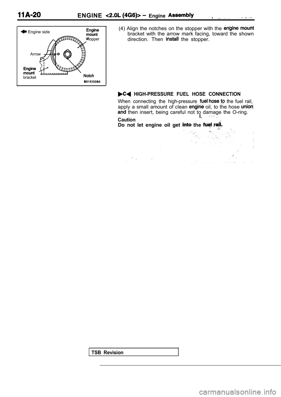
(4) Align the notches on the stopper with the
bracket with the arrow mark facing, toward the show n
direction. Then
the stopper.
HIGH-PRESSURE FUEL HOSE CONNECTION
When connecting the high-pressure the fuel rail,
apply a small amount of clean oil, to the hose
then insert, being careful not to damage the O-rin g.. .
CautionI.
Do not let engine oil get the .
TSB Revision