Page 349 of 2103

ENGINE OVERHAUL Cylinder Head and Valves
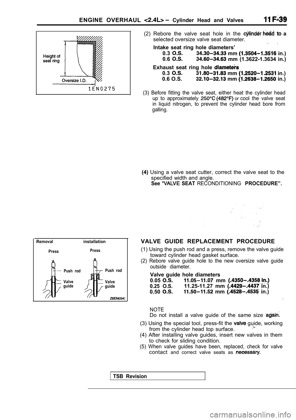
Removalinstallation
Press
A
Press
A
Push rod
Valve
guide Push rod
Valve
guide
(2) Rebore the valve seat hole in the a
selected oversize valve seat diameter.
Intake seat ring hole diameters’
0.3 mm in.)
0.6
mm (1.3622-1.3634 in.)
Exhaust seat ring hole
0.3 mm in.)
0.6 O.S.
mm in.)
(3) Before fitting the valve seat, either heat the cylinder head
up to approximately
or cool the valve seat
in liquid nitrogen, to prevent the cylinder head bo re from
galling.
(4)Using a valve seat cutter, correct the valve seat t o the
specified width and angle.
See SEAT RECONDITIONINGPROCEDURE”.
VALVE GUIDE REPLACEMENT PROCEDURE
(1) Using the push rod and a press, remove the valv e guide
toward cylinder head gasket surface.
(2) Rebore valve guide hole to the new oversize val ve guide
outside diameter.
Valve guide hole diameters
0.05
0.25 O.S.
mm
0.50
11.25-11.27 mm in.)
mm in.)
NOTE
Do not install a valve guide of the same size
(3) Using the special tool, press-fit the guide, working
from the cylinder head top surface.
(4) After installing valve guides, insert new valve s in them
to check for sliding condition.
(5) When valve guides have been, replaced, check fo r valve
contactand correct valve seats as
TSB Revision
Page 517 of 2103
ENGINE (NON-TURBO)> Throttle Body
DISASSEMBLY AND REASSEMBLY
2.2
2I
. .
1. .
steps
1. motor assembly2. Throttle body
DISASSEMBLY SERVICE POINT
MOTOR REMOVAL
Do not disassemble the motor.
2.Do not immerse solvent to clean the sensor and moto r.
Clean them with shop towel.
THROTTLE BODY REMOVAL
1. Do not remove the throttle valve.
2. Check if the vacuum port or passage is clogged. Use
compressed air to clean the vacuum passage.
TSB Revision
Page 650 of 2103
14. Stop the engine and
Normal if the reading does
it observe
repair according to “the table,
SymptomProbable
Fuel pressure drops gradually afterLeaky injector
engine is stopped inject&. . ,
Leaky fuel regulator valve seat
Fuel pressure drops Check is held. .mediately after engine is stopped open
15. Release residual pressure from the fuel pipe li ne.
(Refer
16. Remove the fuel pressure gauge and special tool from
the fuel rail.
Caution
Cover the hose connection with a shop towel to pre-
vent splash of fuel that could be caused by some residual pressure in the fuel pipe line.
17. Replace the O-ring at the end of the fuel high pressure
hose with a new one.
16. Fit the fuel high pressure the fuel rail and tighten
the bolts specified torque.
T i g h t e n i n g
‘Apply
drive drive the fuel pump.
(2) Check
fuel for leaks, repair as needed.
,
,
.
.
Page 673 of 2103
1.4
steps
1. Throttle position sensor (with in closed throttle position switch)2. Idle air control motor
3. Gasket
4. Throttle body
DISASSEMBLY SERVICE POINTS
POSITION SENSOR AND IDLE All?
CONTROL MOTOR REMOVAL
1. Do not disassemble the sensor and motor.
2.Do not immerse solvent to clean the sensor and moto r.
Clean then with shop towel.
REMOVAL
1. Do not remove the throttle valve.
2. Check if the vacuum port or passage is clogged. Use
compressed air to clean the vacuum passage.
REASSEMBLY SERVICE POINT
THROTTLE POSITION SENSOR INSTALLATION
Install the throttle position sensor to the thrott le body
as shown in the diagram.
Throttle position sensor
Page 689 of 2103
FUEL SUPPLY Fuel Filter.
REMOVAL SERVICE
P O I N T S
EYE BOLT REMOVAL
Hold the fuel filter with a spanner and remove the eye bolt.
Caution
As there will be some pressure remaining in the fue l
pipe line, coverit with a shop towel to prevent fuel from
spraying out.
FUEL MAIN PIPE DISCONNECTION
Hold the fuel filter with a spanner and loosen the flare nut.
Then disconnect the fuel main pipe.
TSB Revision
Page 723 of 2103
INTAKE AND EXHAUST Intake Manifold Engine ,
Fuel rail, fuel injectorand pressureregulator
O-ring
REMOVAL SERVICE POINTS
HIGH-PRESSURE FUEL HOSE DISCONNECTION
Relieve pressure in the fuel pipe line to prevent f uel outflow.
(Refer to GROUP On-vehicle Service.)
Caution
Cover fuel pipe line with shop towel after relievin g pres-
sure as certain pressure may still remain.
RAIL, FUEL INJECTOR AND PRESSURE
REGULATOR ASSEMBLY REMOVAL
Remove fuel rail with fuel injector and pressure re gulator
on.
Caution
Do not drop fuel injector when removing fuel rail.
INSTALLATION SERVICE POINTS
RAIL, FUEL INJECTOR AND PRESSURE
REGULATOR ASSEMBLY INSTALLATION
Apply a small amount of new engine oil to the O-rin g.
HIGH-PRESSURE FUEL HOSE CONNECTION
When connecting the high-pressure fuel hose to the fuel rail,
apply a small amount of new engine oil to the hose union,
and then insert, being careful not to damage the O- ring.
Caution
Do not let engine oil get into the fuel rail.
TSB Revision
Page 730 of 2103

INTAKE AND EXHAUST Intake Manifold
REMOVAL SERVICE POINTS
HIGH-PRESSURE FUEL HOSE DISCONNECTION
Relieve pressure in the fuel pipe line to prevent fuel outflow.
(Refer to GROUP On-vehicle Service.)
Caution
Cover fuel pipe line with shop towel after relievin g pres-
sure as certain pressure may
remain.
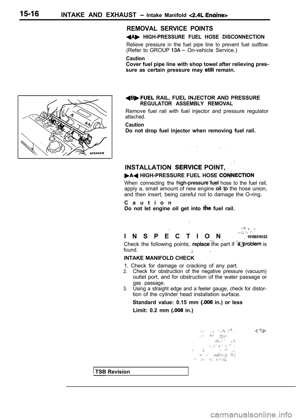
RAIL, FUEL INJECTOR AND PRESSURE
REGULATOR ASSEMBLY REMOVAL
Remove fuel rail with fuel injector and pressure re gulator
attached.
Caution
Do not drop fuel injector when removing fuel rail.
INSTALLATION POINT,
HIGH-PRESSURE FUEL HOSE
When connecting the hose to the fuel rail,
apply a, small amount of new engine the hose union,
and then insert, being careful not to damage the O- ring.
C a u t i o n Do not let engine oil get into
fuel rail.
.
I N S P E C T I O N 15100310123
Check the following points; the part if is
found. .
INTAKE MANIFOLD CHECK 1. Check for damage or cracking of any part.
2.Check for obstruction of the negative pressure (vac uum)
outlet port, and for obstruction of the water passage or
gas passage.
3.Using a straight edge and a feeler gauge, check for distor-
tion of the cylinder head installation surface.
Standard value: 0.15 mm
in.) or less
Limit: 0.2 mm
in.)
TSB Revision
Page 744 of 2103
ENGINE AND EMISSION CONTROL Engine Control
ADJUSTMENT
For models equipped with the auto-cruise
refer to
1. Turn and lights OFF.
Inspect and adjust”
no load.
2. Warm engine until stabilized at
3. Confirm idle at
4. Stop engine (ignition switch OFF).
5. Confirm there are no in
6. Check cable for correct slack:
7.If there is too much
the following procedures.
(1) Turn the ignition switch to ON position (without
starting the
in that condition
motor.’ , ,
4.93.6
TSB Revision
(2) Loosen the adjusting bolt release the cable.
(3) After moving the plate
before the throttle lever starts to
plate back towards the throttle
value amount to biing accelerator cable play
to standard value. .
Standard value: mm in.)
(4) Tighten the adjusting bolts to the specified to rque.
8. Adjust accelerator cable play and confirm thrott le lever
stopper touches the fixed SAS.