1990 MITSUBISHI SPYDER warning
[x] Cancel search: warningPage 2 of 2103
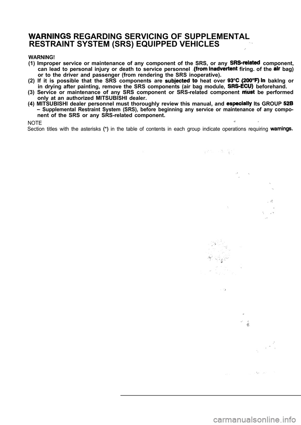
REGARDING SERVICING OF SUPPLEMENTAL
RESTRAINT SYSTEM (SRS) EQUIPPED VEHICLES
WARNING!
(1) Improper service or maintenance of any componen t of the SRS, or any component,
can lead to personal injury or death to service per sonnel
firing. of the bag)
or to the driver and passenger (from rendering the SRS inoperative).
(2) If it is possible that the SRS components are
heat over baklng or
in drying after painting, remove the SRS components (air bag module,
beforehand.
(3) Service or maintenance of any SRS component or SRS-related component
be performed
only at an authorized MITSUBISHI dealer.
(4) MITSUBISHI dealer personnel must thoroughly rev iew this manual, and
Its GROUP
Supplemental Restraint System (SRS), before beginning any service or maintenance of any compo-
nent of the SRS or any SRS-related component.
NOTE
Section titles with the asterisks in the table of contents in each group indicate operations requiring
Page 22 of 2103
GENERAL before Service
PRECAUTIONS BEFORE SERVICE.
SUPPLEMENTAL RESTRAINT SYSTEM
1. to follow when servicing SRS
(1) Be sure to read GROUP Supplemental Restraint System
For safe operations, please follow the directions a nd heed all
(2) Always use the designated special tools and tes t equipment.
(3) Wait at least 60 seconds after disconnecting the battery cable before” further work;
The SRS system is designed to retain enough voltage to deploy the air bag even after the battery
has been disconnected. Serious injury may result from unintended air bag deployment if work
is done on the SRS system immediately after the bat tery cable is disconnected.
(4) Never attempt to disassemble or repair the SRS components (SRS-ECU air bag module and
clock spring). If faulty, replace it.
(5) Warning labels must be heeded when servicing or handling SRS components. Warning labels
are located in the following locations.
Sun visor
l Glove box
. S R S - E C U
l Steering wheel
l Air bag module
l Clock spring
l Steering gear and linkage clamp
(6) Store components removed from the SRS
a clean and dry place.
The air bag module should be stored on a flat surfa ce and placed so that the pad surface is’
facing upward.
Do not place anything on top of it.
(7) Be sure to deploy the air bag before disposing of the air bag’module or disposing of a vehicle
equipped with an air bag. (Refer to GROUP
Air Bag Module Disposal Procedures.)
(8) Whenever you finish servicing the
check the SRS warning light operation to make sure
that the system functions properly.
2.Observe the following when carrying out operations on places where SRS components are installed,’
.,
including operations not directly related to the SR S air bag.
(1) When removing or installing parts do not allow any impact or shock to the SRS components.
(2) SRS components should not be subjected to heat over so remove the SRS compo-
nents before drying or baking the vehicle after painting.
After re-installing them, check the SRS warning lig ht operation to make sure that the system
functions properly.
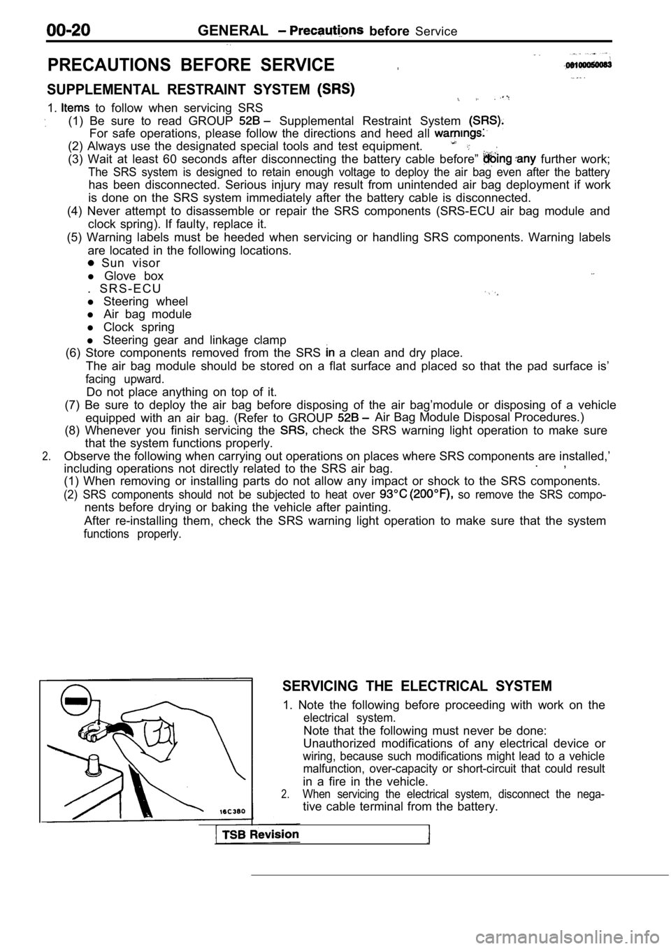
SERVICING THE ELECTRICAL SYSTEM
1. Note the following before proceeding with work o n the
electrical system.
Note that the following must never be done:
Unauthorized modifications of any electrical device or
wiring, because such modifications might lead to a vehicle
malfunction, over-capacity or short-circuit that co uld result
in a fire in the vehicle.
2.When servicing the electrical system, disconnect th e nega-
tive cable terminal from the battery.
Page 53 of 2103
GENERAL Maintenance
21 SYSTEM component
damage, to wiring,
harness, etc.)
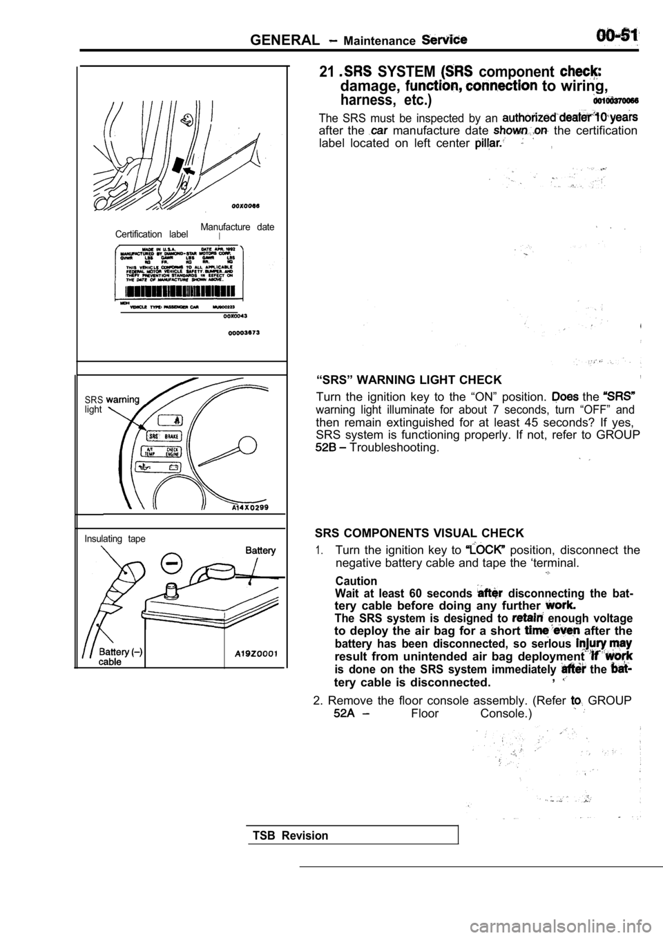
Certification labelManufacture dateI
SRSlight
Insulating tape
The SRS must be inspected by an
after the manufacture date the certification
label located on left center
,
“SRS” WARNING LIGHT CHECK,
Turn the ignition key to the “ON” position. the
warning light illuminate for about 7 seconds, turn “OFF” and
then remain extinguished for at least 45 seconds? I f yes,
SRS system is functioning properly. If not, refer t o GROUP
Troubleshooting.
SRS COMPONENTS VISUAL CHECK
1.Turn the ignition key to position, disconnect the
negative battery cable and tape the ‘terminal.
Caution
Wait at least 60 seconds
disconnecting the bat-
tery cable before doing any further
The SRS system is designed to enough voltage
to deploy the air bag for a short after the
battery has been disconnected, so serlous
result from unintended air bag deployment
is done on the SRS system immediately the
tery cable is disconnected. ,
2. Remove the floor console assembly. (Refer GROUP
Floor Console.)
TSB Revision
Page 374 of 2103
ENGINE LUBRICATION General Information/Lubricants
G E N E R A L I N F O R M A T I O N
The lubrication method is a fully force-fed, full-f low
filtration type.
ENGINE OILS
Health Warning
Prolonged and repeated contact with mineral oil
will result in the removal of natural fats from the
skin, leading to dryness, irritation and dermatitis .
In addition, used engine oil
potentially
Recommended Precautions
The most effective precaution is to adapt working
practices which prevent, as far as practicable, the
risk of skin contact with mineral oils, for example
by using enclosed systems for handling used engine
oil and by degreasing components, where
practicable, before handling them.
Other precautions:
lAvoid prolonged and repeated contact with oils,
particularly used engine oils.
l Wear protective clothing, including impervious
gloves where practicable.
l Avoid contaminating clothes, particularly
underpants, with oil.
l Do not put oily rags in packets, the use of
overalls without pockets will avoid this.
l Do not wear heavily soiled clothing and
oil-impregnated foot-wear. Overalls must be
cleaned regularly and kept separate from
personal clothing.
LUBRICANTS
harmful contaminants which may cause skin cancer.
Adequate means of skin protection and washing
facilities must
provided.
Where there is a risk of eye contact, eye protection should be worn, for example,
chemical goggles or face shields; in addition
an eye wash facility should be provided.
Obtain First Aid treatment immediately for open
cuts and wounds.
Wash regularly with soap and water to ensure
all oil is removed, especially before
cleansers and nail brushes will help). After
cleaning, the application of
containing lanolin to replace the natural
oil is advised.. .
Do not use gasoline, kerosine, diesel fuel,
oil, thinners or solvents for cleaning skin.
Use barrier creams, applying them before each
work period, to help the removal of oil from
the skin after work.
If skin disorders develop, obtain medical advice
without delay.
Items Engine oil (API classification) Quantity (qts.)
Oil filter Engine (Non-turbo)
Engine (Turbo) and
Engine
Oil cooler
Engine (Turbo)>
Total quantity
Engine (Non-turbo)
and
Engine SH or higher
0.5
0.3
0.1
4.3 (4.5)
IIIII
Engine (Turbo) 4.4 (4.6)I
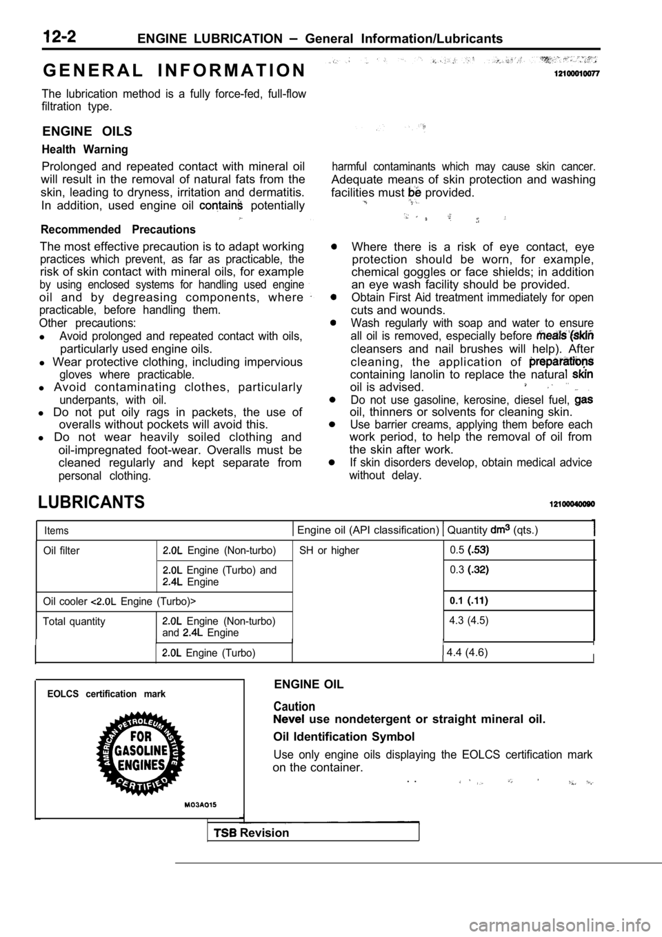
EOLCS certification markENGINE OIL
Caution
use nondetergent or straight mineral oil.
Oil Identification Symbol
Use only engine oils displaying the EOLCS certifica tion mark
on the container.
. .
Revision
Page 384 of 2103
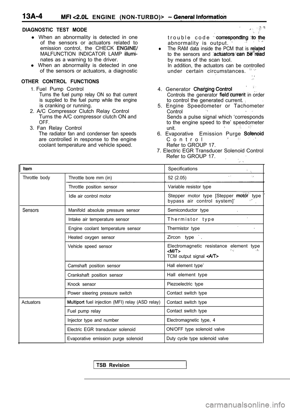
ENGINE (NON-TURBO)>
DIAGNOSTIC TEST MODE
l When an abnormality is detected in one
of the sensors or actuators related to
emission control, the CHECK
MALFUNCTION INDICATOR LAMP
nates as a warning to the driver.
l When an abnormality is detected in one
of the sensors or actuators, a diagnostic
OTHER CONTROL FUNCTIONS
t r o u b l e c o d e
a b n o r m a l i t y i s o u t p u t .
lThe RAM data inside the PCM that is
to the sensors and
by means of the scan tool.
In addition, the actuators can be controlled
under certain circumstances. . ,
1. Fuel Pump Control
Turns the fuel pump relay ON so that current
is supplied to the fuel pump while the engine
is cranking or running.
2. A/C Compressor Clutch Relay Control Turns the A/C compressor clutch ON and
OFF.
3. Fan Relay Control
The radiator fan and condenser fan speeds
are controlled in response to the engine
coolant temperature and vehicle speed. 4. Generator
Controls the generator in order
to control the generated current.
5. Engine Speedometer or Tachometer
Control.
Sends a pulse signal which ‘corresponds
to the engine speed to the’ speedometer
unit..
6. Evaporative Emission Purge
C o n t r o l
Refer to GROUP 17.
7. Electric EGR Transducer Solenoid Control Refer to GROUP 17.
Throttle body
Sensors
Actuators
Specifications
Throttle bore mm (in) 52 (2.05)
Throttle position sensor Variable resistor type
Idle air control motor
Stepper motor type [Stepper type
bypass air control system]’,
Manifold absolute pressure sensor Semiconductor type
Intake air temperature sensorT h e r m i s t o r t y p e
Engine coolant temperature sensorThermistor type .
Heated oxygen sensorZircon type .
Vehicle speed sensorElectromagnetic resistance element type
TCM output signal
Camshaft position sensor Hall element type’
Crankshaft position sensor
Hall element type
Knock sensor Piezoelectric type
Power steering pressure switch Contact switch type
fuel injection (MFI) relay (ASD relay)
Contact switch type
Fuel pump relay Contact switch type
Injector type and number Electromagnetic type, 4
Electric EGR transducer solenoid ON/OFF type solenoid valve
Evaporative emission purge solenoid Duty cycle type solenoid valve
TSB Revision
Page 499 of 2103
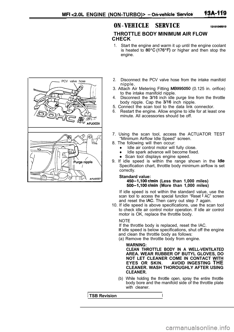
ENGINE (NON-TURBO)>
ON-VEHICLE SERVICE
THROTTLE BODY MINIMUM AIR FLOW
CHECK
1.Start the engine and warm it up until the engine co olant
is heated to
or higher and then stop the
engine.
PCV valve hose2.Disconnect the PCV valve hose from the intake manif old
n i p p l e .
3. Attach Air Metering Fitting
(0.125 in. orifice)
to the intake manifold nipple.
4.Disconnect the inch idle purge line from the throttle
body nipple. Cap the inch nipple.
5. Connect the scan tool to the data link connector .
6.Restart the engine. Allow engine to idle for at least one
minute. All accessories should be off.
7. Using the scan tool, access the ACTUATOR TEST “Minimum Airflow Idle Speed” screen.
8. The following will then occur:
lIdle air control motor will fully close.
lIdle spark advance will become fixed.
l Scan tool displays engine speed.
9. If idle speed is within the range shown in the
Specification chart, throttle body minimum airflow is set
correctly.
Standard value:
(Less than 1,000 miles)
(More than 1,000 miles)
If idle speed is not within the standard value, use the
scan tool to access the special function “Reset AC” screen
and reset the Then carry out step 7 again.
10. If idle speed is above specifications, use the scan tool
to check idle air control motor operation. If idle air control
motor is OK, replace the throttle body.
NOTE
If the throttle body is replaced, reset the IAC.
idle speed is below specifications, shut off the e ngine
and clean the throttle body as follows: (a) Remove the throttle body from engine.
WARNING:
CLEAN THROTTLE BODY IN A WELL-VENTILATED
AREA. WEAR RUBBER OF BUTYL GLOVES, DO
NOT LET CLEANER COME IN CONTACT WITH
EYES OR SKIN. AVOID INGESTING THE
CLEANER. WASH THOROUGHLY AFTER USING
CLEANER.
(b) While holding the throttle open, spray the entir e throttle
body bore and the manifold side of the throttle plate
with cleaner.
TSB RevisionI
Page 519 of 2103
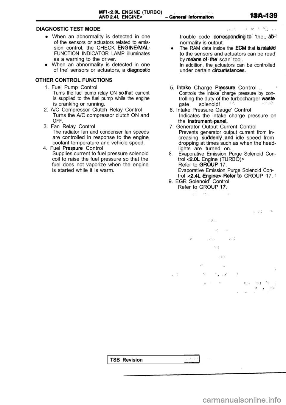
ENGINE (TURBO)
ENGINE>
DIAGNOSTIC TEST MODEl When an abnormality is detected in one
of the sensors or actuators related to emis-
sion control, the CHECK
FUNCTION INDICATOR LAMP illuminates
as a warning to the driver.
l When an abnormality is detected in one
of the’ sensors or actuators, a
OTHER CONTROL FUNCTIONS
1. Fuel Pump Control
Turns the fuel pump relay ON current
is supplied to the fuel pump while the engine
is cranking or running.
2. A/C Compressor Clutch Relay Control Turns the A/C compressor clutch ON and
OFF.
3. Fan Relay Control
The radiator fan and condenser fan speeds
are controlled in response to the engine
coolant temperature and vehicle speed.
4. Fuel
Control
Supplies current to fuel pressure solenoid
coil to raise the fuel pressure so that the
fuel does not vaporize when the engine
is started while it is warm.
trouble code ‘the,,
normality is output.
lThe RAM data inside the that
to the sensors and actuators can be read’
by
scan’ tool.
addition, the actuators can be controlled
under certain
5. Charge Control
Controls the intake charge pressure by con-
trolling the duty of the turbocharger
gate solenoid!
6. Intake Pressure Gauge’ Control Indicates the intake charge pressure on
the
7. Generator Output Current Control
Prevents generator output current from in-
creasing idle speed from
dropping at times such as when the head-
lights are turned on.
8.Evaporative Emission Purge Solenoid Con-
trol Engine (TURBO)>
Refer to
17.
Evaporative Emission Purge Solenoid Con-
trol GROUP 17.
9. EGR Solenoid’ Control
Refer to GROUP
,,
,
TSB Revision
Page 741 of 2103

CONTENTS
AUTO-CRUISE CONTROL SYSTEM
. . . . . . . . . . . . . . . . . . . . . . . . . . . . . . . . . . . . .7
AUTO-CRUISE CONTROL* . . . . . . . . . . . . . . 40
GENERAL INFORMATION . . . . . . . . . . . . . . . . 7
ON-VEHICLE SERVICE. . . . . . . . . . . . . . . . . 33
Auto-cruise Control Cable Check and
Adjustment . . . . . . . . . . . . . . . . . . . . . . . . . . . . . .
33
Auto-cruise Control Component Check . . . . . 37
Auto-cruise Control System Operation Check
. . . . . . . . . . . . . . . . . . . . . . . . . . . . . . . . . . . . . . . . .
35
SERVICE SPECIFICATIONS . . . . . . . . . . . . . 8
SPECIAL TOOLS . . . . . . . . . . . . . . . . . . . . . . . . 8
TROUBLESHOOTING
ENGINE (NON-TURBO)> . . . . . . . . . . . 9
TROUBLESHOOTING
(TURBO) AND ENGINE> . . . . .
EMISSION CONTROL’ SYSTEM
. . . . .
CATALYTIC . . . . . . . . . . . . . .
General Information . . . . . . . . . . . . . . . . . . 57
EVAPORATIVE EMISSION .
SYSTEM. . . . . . . . . . . . . . . .
Air Conditioning . . . . . . . . . . . . . . . . . . . 52
Component Location
. . . . . . . . . . . . . . . . . .
Engine Coolant Temperature Sensor
Intake Air Temperature Sensor . . . . . . . . . . . . 52
WARNINGS REGARDING SERVICING OF SUPPLEMENTAL RESTRA INT SYSTEM (SRS) EQUIPPED
WARNING!
(1) Improper serviceor maintenance of any component of the or any SRS-related can to injuryorcleathtoservicepersonnel (from inadvertentfiring the SRS inoperative).
(2) Service or maintenance of any SRS component or SRS-related component must be performed only
MITSUBISHI dealer.
(3) MITSUBISHI dealer personnel must thoroughly rev iew this manual, and especially its GROUP
Restraint System (SRS) and GROUP 00 Maintenance Service, before any service or maintenance of any
componentof the SRS or any SRS-related component.
NOTEJhe includes the following components: warning light, air bag module, clock components (that may have to be removed/installed in connection with or areIndicated in the table of contents by an asterisk