Page 1009 of 2103
CONTENTS
AUTOMATIC TRANSAXLE
ENGINE (NON-TURBO)> . . . . . 115
AUTOMATIC TRANSAXLE KEY INTERLOCK
AND SHIFT LOCK MECHANISMS* . . . . . . . . 192
GENERAL INFORMATION
. . . . . . . . . . . . . . . . 115
LUBRICANTS. . . . . . . . . . . . . . . . . . . . . . . . . . . .117
ON-VEHICLE SERVICE . . . . . . . . . . . . . . . . . . . 159
Automatic Transaxle Control Component
Oil Temperature Sensor Continuity Check . . . . 160
Pinion Factor Writing Procedure After
TCM Replacement or Tire Size Change
. . . 159
Selector Level Operation Check . . . . . . . . . . . . . . ,166
Shift Lock Mechanism Check. . . . . . . . . . . . . . .
1 8 6
TCM Resetting Procedure . . . . . . . . . . . . .
..159
Torque Converter Stall Testing. . . . . . . . . . . . . .166
Transaxle Fluid Level Check . . . . . . . . . . .. . .159
Transaxle Fluid Replacement. . . . . . . . . . . . . . .
Transaxle Range Sensor Continuity . . .
Check. . . . . . . . . . . . . . . . . . . . . . . . . . . . . . . . . . . .163SERVICE SPECIFICATIONS.. . . .. . .Automatic Transaxle Control Component Layout
. . . . . . . . . . . . . . . . . . . . . . . . . . . . . . . . . . . . . . . . . . .
161SPECIAL TOOLS. . . . . . . . . . . . . . . . . . . . . . . . .117Clutch Air Pressure Tests . . . . . . . . . . . . . . . . . . .168
Fluid Leakage-Torque Converter Housing Area
Check. . . . . . . . . . . . . . . . . . . . . . . . . . . . . . . . . . . .169
Hydraulic Pressure Tests. . . . . . . . . . . . . . . . . . .169
Hydraulic Circuit. . . . . . . . . . . . . . . . . . . . . . . . . . .173
TRANSAXLE ASSEMBLY. . . . . . . . . . . . . . . .
TRANSAXLE CONTROL*. . . . . . . . . . . . . . . . .187
Selector Lever Assembly. . . . . . . . . . . . . . . . . . .189
Key Interlock Mechanism Check . . . . . . . . . . .
. 186CONTINUED ON NEXT PAGE
WARNINGS REGARDING SERVICING OF SUPPLEMENTAL EQUIPPED VEHICLES
WARNING! (1) Improper service or maintenance of any componen t of the
or any component, can lead to personal
injuryordeath inadvertent the inoperative).
(2) Service or maintenance of any component or SRS-related component must be perform ed only at an authorized
MITSUBISHI dealer.
(3)MITSUBISHI dealer personnel must thoroughly review this manual, and especially its GROUP Supplemental Re-
straint System (SRS) and GROUP 00 -Maintenance Serv ice before beginning any service or maintenance of any com-
ponent of the
or any component.
NOTEThe SRS includes the following components: SRS-ECU, SRS warning light, air bag module, clockspring and inte rconnecting wiring.Other SRS-related components (that may have to be removed/installed in connection with SRS service or maintenance) are indi-cated in the table of contents by an asterisk
Page 1261 of 2103
AUTOMATIC
Rear
750274
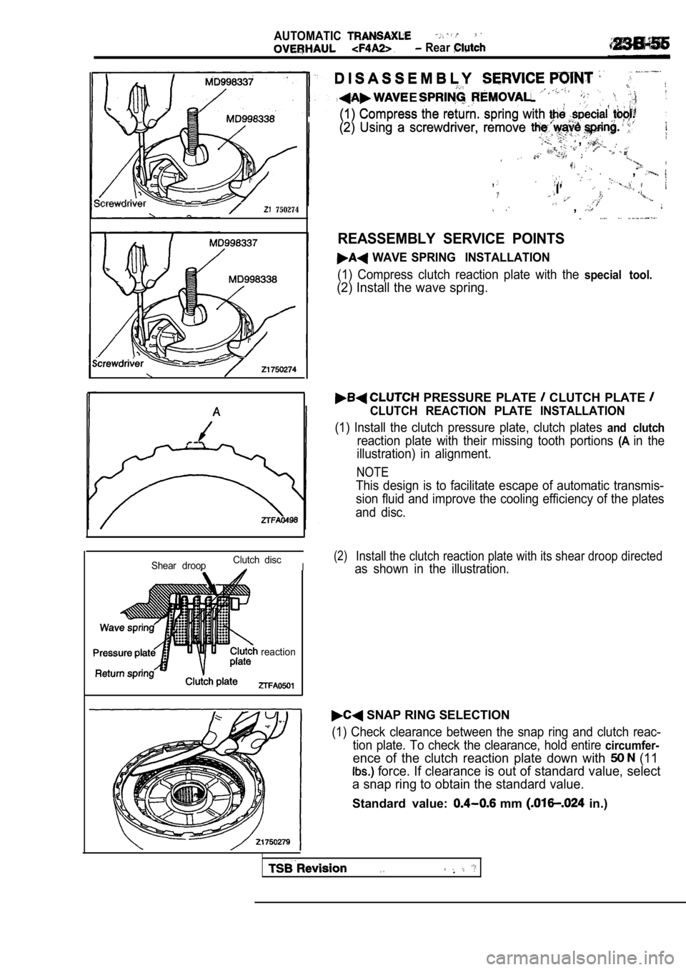
D I S A S S E M B L YD I S A S S E M B L Y
WAVE
(1) Compress the return. spring with (1) Compress the return. spring with
(2) Using a screwdriver, remove (2) Using a screwdriver, remove
,,
,,
,,,,
I’I’
,,
REASSEMBLY SERVICE POINTS
WAVE SPRING INSTALLATION
(1) Compress clutch reaction plate with the special tool.
(2) Install the wave spring.
Shear droopClutch disc,I
reaction
PRESSURE PLATE CLUTCH PLATE
CLUTCH REACTION PLATE INSTALLATION
(1) Install the clutch pressure plate, clutch plate
s and clutch
reaction plate with their missing tooth portions (Ain the
illustration) in alignment.
NOTE
This design is to facilitate escape of automatic tr ansmis-
sion fluid and improve the cooling efficiency of th e plates
and disc.
(2)Install the clutch reaction plate with its shear dr oop directed
as shown in the illustration.
SNAP RING SELECTION
(1) Check clearance between the snap ring and clutc h reac-
tion plate. To check the clearance, hold entire
circumfer-
ence of the clutch reaction plate down with (11
force. If clearance is out of standard value, sele ct
a snap ring to obtain the standard value.
Standard value: mm in.)
Page 1365 of 2103
A U T O M A T I C
Rear
,
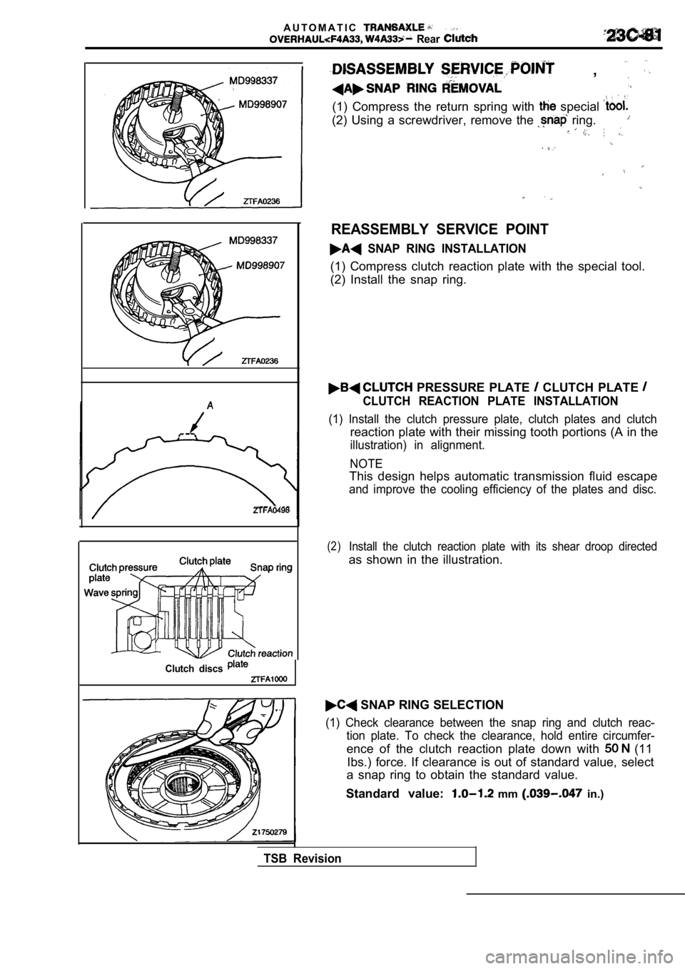
(1) Compress the return spring with special
(2) Using a screwdriver, remove the ring.
Clutch discs
REASSEMBLY SERVICE POINT
SNAP RING INSTALLATION
(1) Compress clutch reaction plate with the special tool.
(2) Install the snap ring.
PRESSURE PLATE CLUTCH PLATE
CLUTCH REACTION PLATE INSTALLATION
(1) Install the clutch pressure plate, clutch plate s and clutch
reaction plate with their missing tooth portions (A in the
illustration) in alignment.
NOTE
This design helps automatic transmission fluid esca pe
and improve the cooling efficiency of the plates and disc.
(2)Install the clutch reaction plate with its shear droop directed
as shown in the illustration.
SNAP RING SELECTION
(1) Check clearance between the snap ring and clutc h reac-
tion plate. To check the clearance, hold entire cir cumfer-
ence of the clutch reaction plate down with (11
Ibs.) force. If clearance is out of standard value, select
a snap ring to obtain the standard value.
Standard value:
mm in.)
TSB Revision
Page 1585 of 2103
CONTENTS
GENERAL INFORMATION. . . . . . . . . . . . . . . . . .2
ON-VEHICLE SERVICE. . . . . . . . . . . . . . . . . . . . .5
Tire Inflation Pressure Check. . . . . . . . . . . . . . . . .
Tire Wear Check. . . . . . . . . . . . . . . . . . . . . . . . . . . .‘5
Wheel Check . . . . . . . .. . . . .. . . . . . . .5
SERVICE SPECIFICATIONS . . . . . . . . . .
TROUBLESHOOTING . . . . . . . . . . . . . . . . . . . . .
WHEEL AND TIRE
.. . . . . . . . . . . . . . . . . . . . . . . . .
Page 1588 of 2103
WHEEL AND TIRE
Symptom
Rapid wear at
shouldersProbable cause
Under-inflationor lack of
tion
Remedy Reference
Adjust the tire
Refer to
p r e s s u r e .
Rapid wear at
Over-inflation or
center
lack of rotation
I
treads Under-inflation Adjust the tireRefer to
pressure.
Wear on one side
Excessive
ber Check thecamber.
Refer to GROUP On-vehicle
Service.
Feathered edge Incorrect toe-in
Adjust the
toe-in.
Bald spots Unbalanced
wheel
Adjust the
wheels.
Scalloped wear Lack of rotation of tires or
worn orRotate the Refer to GROUP
out-of-alignment suspension check the front On-vehicle
suspension Service.
alignment.
TSB Revision
Page 1589 of 2103
WHEEL AND TIRE On-vehicle Service/Wheel and Tire
Wear indicator
TIRE INFLATION PRESSURE CHECK
NOTERefer to the inflation pressure label on the driver ’s side door.
TIRE WEAR CHECK
Measure the tread depth of tires.
Limit: 1.6 mm
in.)
If the remaining tread depth is less than the limit , replace
the tire.
NOTE
When the tread depth of tires is reduced to 1.6 mm
or less, wear indicators will appear.
WHEEL
CHECK
Jack up the vehicle so that the wheels are clear of the floor.
While slowly turning the wheel, measure wheel with
a dial indicator.
Limit:
Radial
Steel wheel; 1.2 mm in.) or less
Aluminum wheel; 1.0 mm
in.) or less
Lateral
Steel wheel; 1.2 mm in.) or less
Aluminum wheel; 1.0 mm
in.) or less
If wheel
exceeds the limit, replace the wheel.
INSTALLATION SERVICE POINT
Tighten the wheel nut to the specified torque.
Tightening torque:
Nm
TSB Revision
Page 1604 of 2103
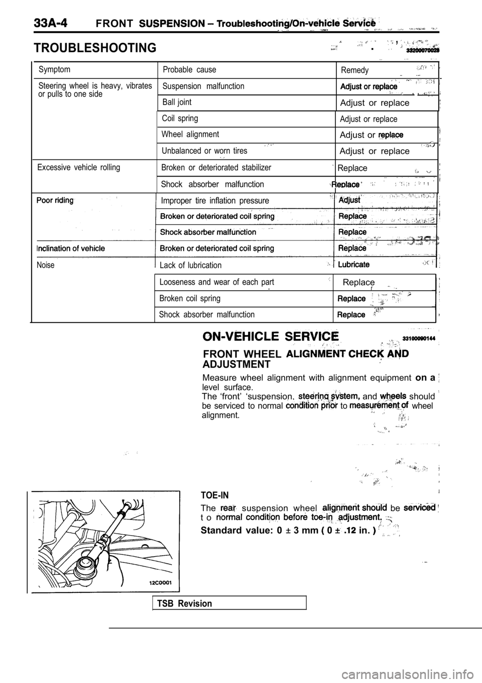
FRONT __
TROUBLESHOOTING
, .
SymptomProbable cause
Remedy
Steering wheel is heavy, vibratesSuspension malfunction
or pulls to one side, ,
Ball jointAdjust or replace
Coil spring
Wheel alignment
Unbalanced or worn tires Adjust or replace
Adjust or
Adjust or replace
Excessive vehicle rollingBroken or deteriorated stabilizer
Shock absorber malfunction
Replace
Improper tire inflation pressure
NoiseLack of lubrication
Looseness and wear of each part
.
Broken coil spring
Shock absorber malfunction
Replace
FRONT WHEEL
ADJUSTMENT
Measure wheel alignment with alignment equipment on a
level surface.
The ‘front’ ‘suspension, and should
be serviced to normal to wheel
alignment.
TOE-IN
The suspension wheel be
t o
Standard value: 0 3 mm 0 in.
TSB Revision
Page 1621 of 2103
SymptomProbable cause Remedy
Squeaks or other Loose rear suspension mounting bolts and nutsRetighten
normal noise Malfunction of shock absorber Replace
W o r n b u s h i n g s
Upper arms and/or lower arms and/or toe control
arm deformed or damaged
Trailing arms deformed or damaged
Crossmember deformed or damaged
Poor ride Excessive tire inflation pressure Adjust the pressure
Malfunction of shock absorber
Replace
Weak or broken springs
Stabilizer bar and/or stabilizer link
or damaged.
Body tilting Weak or deteriorated bushings Replace
Weak or broken springs
Upper arms and/or lower arms and/or toe control
arm deformed or damaged
Trailing arms deformed or damaged
Crossmember deformed or damaged
REAR SUSPENSION
TROUBLESHOOTING
TSB Revision