1990 MITSUBISHI SPYDER check engine
[x] Cancel search: check enginePage 23 of 2103
GENERAL Precautions before Service . .
Caution
1.Before connecting or disconnecting the negative
be sure to turn off the ignition and
the lighting switch.
(if this is not done, the possibility semi-
conductor parts being damaged.)
2.After completion of the work steps [when the bat-
tery’s negative terminal is connected], warm
up the engine and allow it for approximately
five minutes under the conditions be-
low, in order to stabilize the engine condi-
tions, and then check to be sure that idling’ is
satisfactory.
Engine temperature:
Lights, electric fans, accessories: OFF
Transaxle: Neutral position
(A/T models: “N” or “P”)
Steering
neutral (center) position
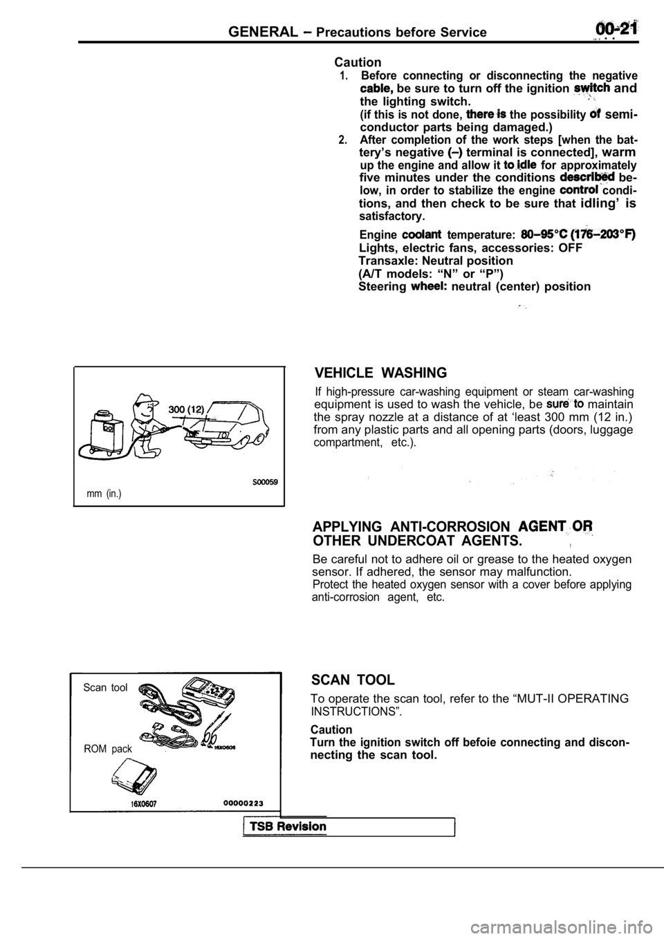
mm (in.)
Scan tool
ROM pack
VEHICLE WASHING
If high-pressure car-washing equipment or steam car -washing
equipment is used to wash the vehicle, be maintain
the spray nozzle at a distance of at ‘least 300 mm (12 in.)
from any plastic parts and all opening parts (doors , luggage
compartment, etc.).
APPLYING ANTI-CORROSION
OTHER UNDERCOAT AGENTS.,
Be careful not to adhere oil or grease to the heate d oxygen
sensor. If adhered, the sensor may malfunction.
Protect the heated oxygen sensor with a cover befor e applying
anti-corrosion agent, etc.
SCAN TOOL
To operate the scan tool, refer to the “MUT-II OPER ATING
INSTRUCTIONS”.
Caution
Turn the ignition switch off befoie connecting and discon-
necting the scan tool.
Page 29 of 2103
GENERAL Special Handling Instructions for Models
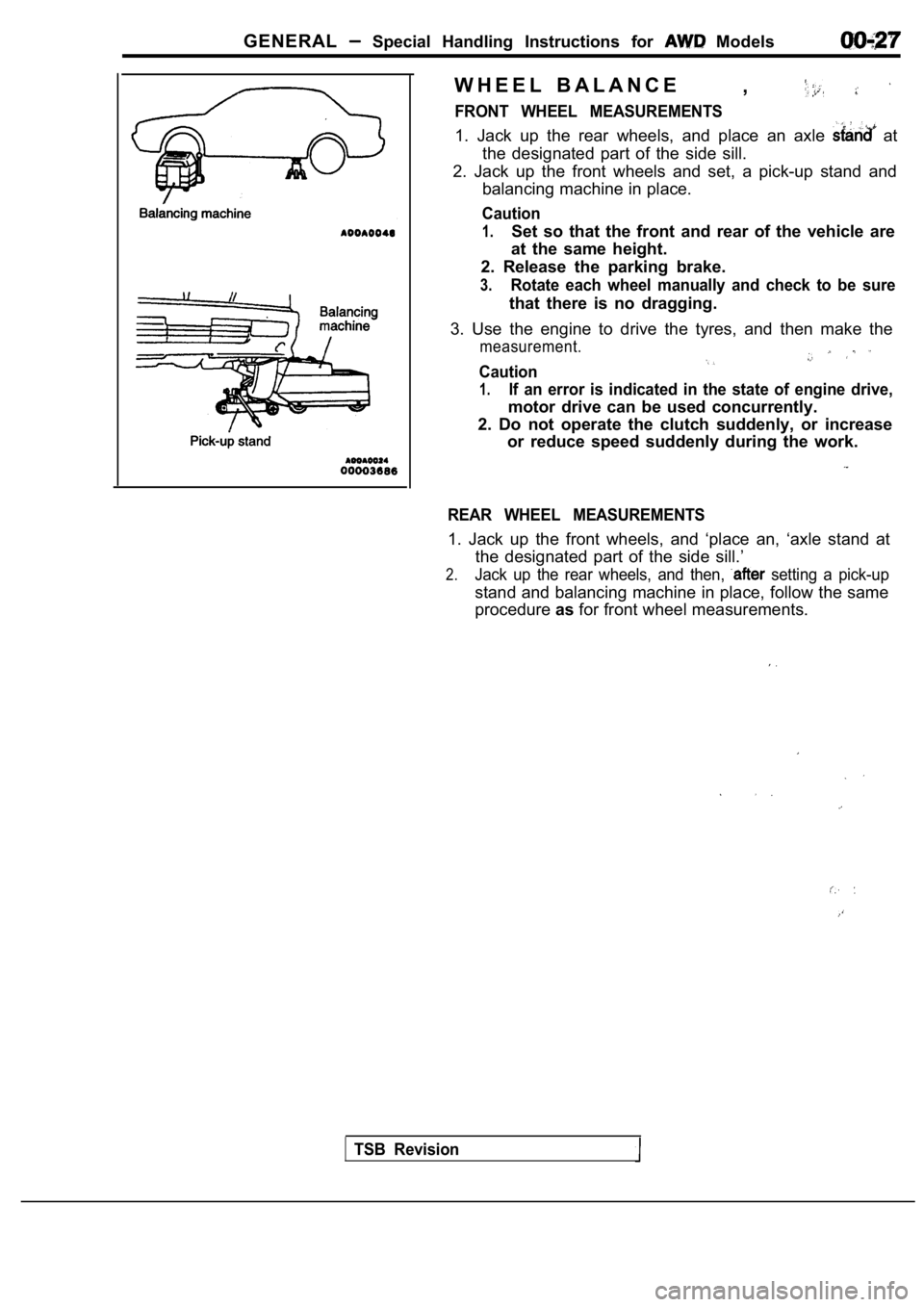
W H E E L B A L A N C E,
FRONT WHEEL MEASUREMENTS
1. Jack up the rear wheels, and place an axle at
the designated part of the side sill.
2. Jack up the front wheels and set, a pick-up stan d and
balancing machine in place.
Caution
1.Set so that the front and rear of the vehicle are
at the same height.
2. Release the parking brake.
3.Rotate each wheel manually and check to be sure
that there is no dragging.
3. Use the engine to drive the tyres, and then make the
measurement.
Caution
1.If an error is indicated in the state of engine drive,
motor drive can be used concurrently.
2. Do not operate the clutch suddenly, or increase or reduce speed suddenly during the work.
REAR WHEEL MEASUREMENTS
1. Jack up the front wheels, and ‘place an, ‘axle s tand at
the designated part of the side sill.’
2.Jack up the rear wheels, and then, setting a pick-up
stand and balancing machine in place, follow the sa me
procedure asfor front wheel measurements.
TSB Revision
Page 41 of 2103
GENERAL Maintenance Service
Engine (Non-turbo)>
Engine (Turbo)>
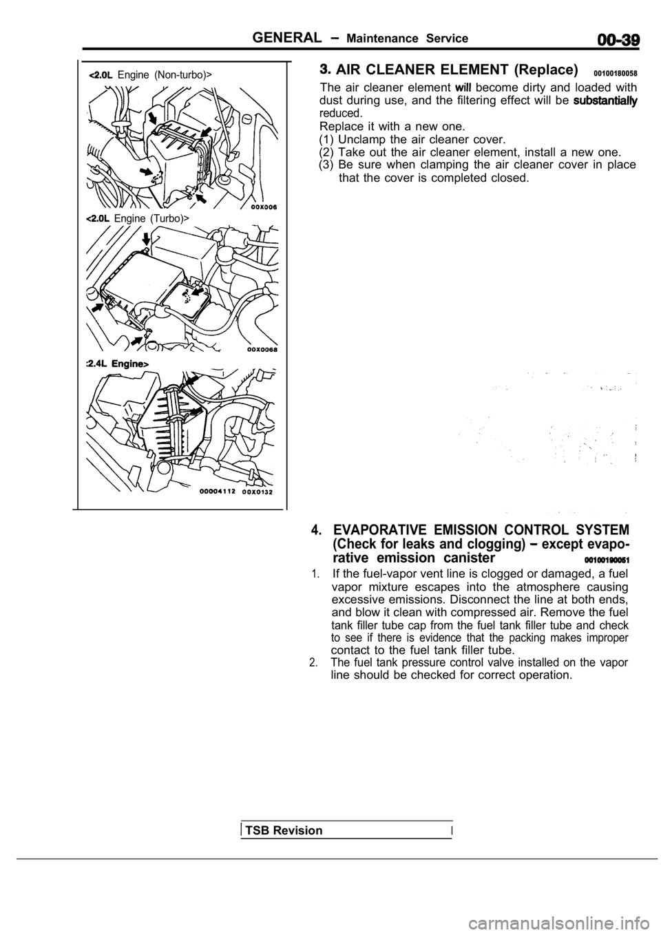
AIR CLEANER ELEMENT (Replace)00100180058
The air cleaner element become dirty and loaded with
dust during use, and the filtering effect will be
reduced.
Replace it with a new one.
(1) Unclamp the air cleaner cover.
(2) Take out the air cleaner element, install a new one.
(3) Be sure when clamping the air cleaner cover in place
that the cover is completed closed.
4.EVAPORATIVE EMISSION CONTROL SYSTEM
(Check for leaks and clogging)
except evapo-
rative emission canister
1.If the fuel-vapor vent line is clogged or damaged, a fuel
vapor mixture escapes into the atmosphere causing
excessive emissions. Disconnect the line at both en ds,
and blow it clean with compressed air. Remove the f uel
tank filler tube cap from the fuel tank filler tube and check
to see if there is evidence that the packing makes improper
contact to the fuel tank filler tube.
2.The fuel tank pressure control valve installed on the vapor
line should be checked for correct operation.
TSB RevisionI
Page 42 of 2103

GENERAL Maintenance
Incorrect Correct
5. SPARK PLUGS
1.Spark plugs must spark properly to assure proper engine
performance and reduce exhaust emission
Therefore, they should be periodically with new
ones.
2. The new plugs should be checked gap.
Spark plug gap:, . .
Engine (Turbo)>’
mm
Engine (Non-turbo)> ,
1.22-1.35 mm
in.)
Engine> .
in.)
3. Install the spark plug and tighten to the
Tightening torque:
Engine (Turbo) and Engine>
25 Nm (18
E n g i n e ( N o n - t u r b o ) >
28 Nm (20
6. IGNITION CABLES (Replace)
The ignition cables should. be replaced periodicall y with new
ones. After replacing, make sure that the ignition cables are
routed properly and fully seated.
NOTE
When disconnecting an ignition cable; be sure to ho ld the
cable boot. If the cable is disconnected by pulling on the
cable alone, an open circuit might result.
7. TIMING BELT (Replace)
00100220027
Replace the belt with a new one periodically to ass ure proper
engine performance.
For disassembly and assembly procedures; Refer to GROUP
Timing Belt.
Refer to GROUP
Timing Belt.
Refer to GROUP 11
Timing Belt.
8. DRIVE BELT (For Generator, Water Pump, Power Steering Pump) (Check condition)
Check the tension of the drive belt. Check the driv e belt
for evidence of cuts and cracks, and replace it if defective.
TSB Revision
Page 43 of 2103

GENERAL Maintenance
Generator pulley
Crankshaft
Water pump
pump
GENERATOR AND WATER PUMP DRIVE
CHECK
Engine (Turbo) and Engine>
Check the belt tension with the tension gauge, or c heck the
belt deflection by pressing. the middle point of
belt by
force of 98 (22 Ibs.).
Standard value:
Tension (Ibs.)
Deflection mm (in.)
9.0 11.5
,
Engine (Non-turbo)>
Check the belt tension with the tension gauge at th e middle
point of the belt, or check the belt deflection by pressing,
the belt point by a force of 98
(22 Ibs.). .
Standard value:
Tension (Ibs.)
Deflection mm (in.)
4 0 0 490 (90 --
9.0 12.0
POWER STEERING PUMP DRIVE BELT TENSION CHECK
Engine (Turbo) and Engine>
1. Pull or push at the mid point of the belt with a force
of 98
(22 Ibs.) to measure dirve belt deflection.
Standard value:
mm in.)
2. Use a tension gauge to measure belt tension. S t a n d a r d v a l u e :
TSB Revision
Page 44 of 2103
GENERALMaintenanceService
Drain
Oil pan side
Engine
Engine (Turbo) and
TSB Revision
Engine (Non-turbo)>
1. Pull orpush at the mid point of the belt with aforce
of 98
(22 Ibs.) to measure dirve belt deflection.
Standard value:
mm in.)
2. Use a tension gauge to measure belt
Standard value:
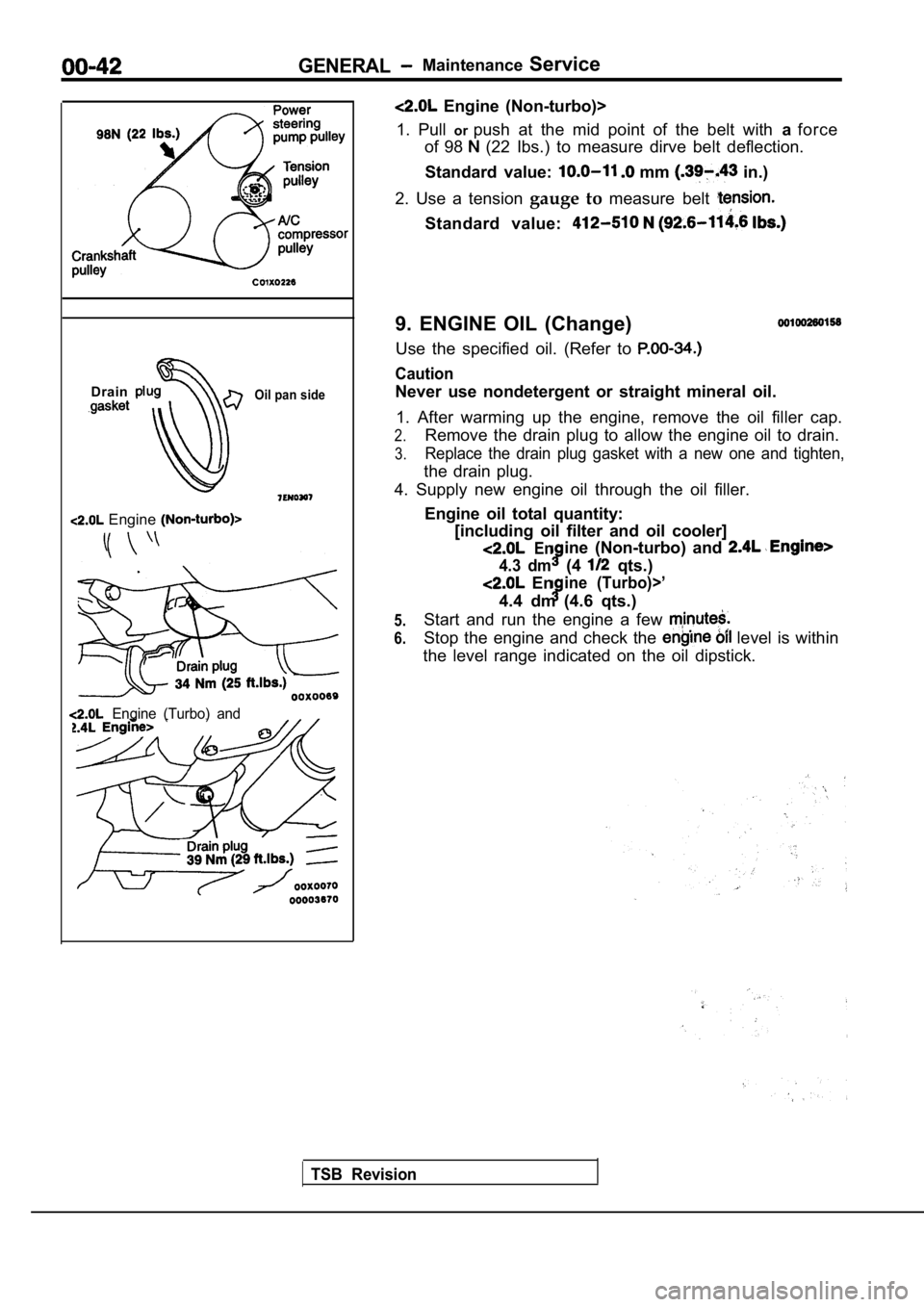
9. ENGINE OIL (Change)
Use the specified oil. (Refer to
Caution
Never use nondetergent or straight mineral oil.
1. After warming up the engine, remove the oil fill er cap.
2.Remove the drain plug to allow the engine oil to drain.
3.Replace the drain plug gasket with a new one and ti ghten,
the drain plug.
4. Supply new engine oil through the oil filler.
Engine oil total quantity:[including oil filter and oil cooler]
Enine (Non-turbo) and
4.3 dm(4 qts.)
Enine (Turbo)>’
4.4 dm (4.6 qts.)
Start and run the engine a few
Stop the engine and check the level is within
the level range indicated on the oil dipstick.
5.
6.
Page 46 of 2103
GENERAL
Oil level
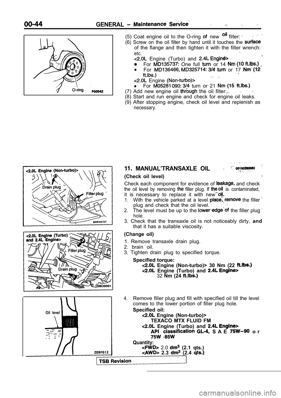
(5) Coat engine oil to the O-ring new filter:
(6) Screw on the oil filter by hand until it touches the
of the flange and then tighten it with the filter w rench:. . .etc..
Engine (Turbo) and
For One full or 14 ,
lFor or 17 ,
Engine
lFor turn or 21
(7) Add new engine oil the oil filter...
(8) Start and run engine and check for engine oil l eaks.
(9) After stopping engine, check oil level and repl enish as
necessary.
MANUAL’TRANSAXLE OIL
(Check oil level)
Check each component for evidence of and check
the oil level by removing filler plug. If is contaminated,
it is necessary to replace it with new
1.With the vehicle parked at a level the filler
plug and check that the oil level..
2.The level must be up to the the filler plug
hole.
3. Check that the transaxle oil is not noticeably d irty, and
that it has a suitable viscosity.
(Change oil) 1. Remove transaxle drain plug.
2. brain oil.
3. Tighten drain plug to specified torque.
Specified torque:
Engine (Non-turbo)> 30 Nm (22
Engine (Turbo) and
32Nm (24
4.Remove filler plug and fill with specified oil till the level
comes to the lower portion of filler plug hole.
Specified oil:
Engine (Non-turbo)>
TEXACO MTX FLUID FM
Engine (Turbo) and
S A E o r
Quantity:
2.0 (2.1 qts.)
2.3 (2.4
Page 47 of 2103
GENERAL Maintenance, Service
5. Tighten filler plug to specified torque.
Specified torque:
Engine (Non-turbo)>30 Nm (22
Engine (Turbo) and Engine>
32 Nm (24
12. AUTOMATIC TRANSAXLE FLUID
(Check ‘fluid level)
Engine (Non-turbo)>
1. Position the vehicle on a level surface.
2. Start engine and allow to idle in PARK for at le ast 60
seconds. The warmer the transaxle fluid, the more
accurate the reading.
3.While sitting in driver seat, apply brakes and plac e gear
selector in each position. Return gear selector to PARK.
4. Raise hood and remove transaxle fluid level indi cator
(dipstick) and wipe clean with a suitable shop towe l.
5.
dipstick and verify it is seated in fill tube.
Caution
Do not overfill automatic transaxle, leakage or dam age
can result.
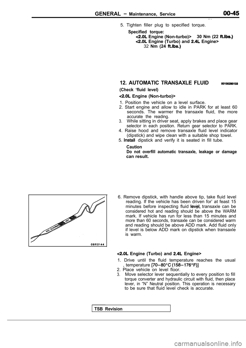
6. Remove dipstick, with handle above tip, take flu id level
reading. If the vehicle has been driven for’ at fea st 15
minutes before inspecting fluid
transaxle can be
considered hot and reading should be above the WARM
mark. If vehicle has run for less than 15 minutes a nd
more than 60 seconds, transaxle can be considered w arm
and reading should be above ADD mark. Add fluid onl y
if level is below ADD mark on dipstick when transax le
is warm.
Engine (Turbo) and Engine>
1. Drive until the fluid temperature reaches the us ual
, temperature
2. Place vehicle on level floor.
3.Move selector lever sequentially to every position to fill
torque converter and hydraulic circuit with fluid, then place
lever, in “N” Neutral position. This operation is n ecessary
to be sure that fluid level check is accurate.
TSB Revision