1990 MITSUBISHI SPYDER check engine
[x] Cancel search: check enginePage 48 of 2103
GENERAL Maintenance
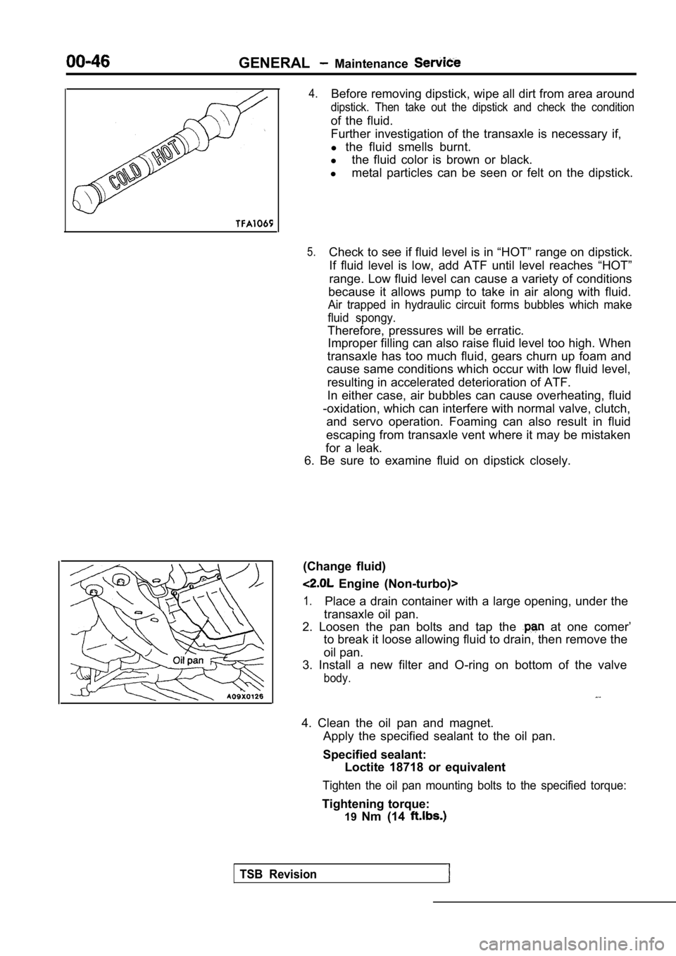
4.Before removing dipstick, wipe all dirt from area around
dipstick. Then take out the dipstick and check the condition
of the fluid.
Further investigation of the transaxle is necessary if,
l the fluid smells burnt.
l the fluid color is brown or black.
l metal particles can be seen or felt on the dipstick .
5.Check to see if fluid level is in “HOT” range on dipstick.
If fluid level is low, add ATF until level reaches “HOT”
range. Low fluid level can cause a variety of condi tions
because it allows pump to take in air along with fl uid.
Air trapped in hydraulic circuit forms bubbles which make
fluid spongy.
Therefore, pressures will be erratic. Improper filling can also raise fluid level too hig h. When
transaxle has too much fluid, gears churn up foam a nd
cause same conditions which occur with low fluid le vel,
resulting in accelerated deterioration of ATF.
In either case, air bubbles can cause overheating, fluid
-oxidation, which can interfere with normal valve, clutch,
and servo operation. Foaming can also result in flu id
escaping from transaxle vent where it may be mistak en
for a leak.
6. Be sure to examine fluid on dipstick closely.
(Change fluid)
Engine (Non-turbo)>
1.Place a drain container with a large opening, under the
transaxle oil pan.
2. Loosen the pan bolts and tap the
at one comer’
to break it loose allowing fluid to drain, then rem ove the
oil pan.
3. Install a new filter and O-ring on bottom of the valve
body.
4. Clean the oil pan and magnet.
Apply the specified sealant to the oil pan.
Specified sealant: Loctite 18718 or equivalent
Tighten the oil pan mounting bolts to the specified torque:
Tightening torque:
19Nm (14
TSB Revision
Page 49 of 2103
GENERALMaintenance Service
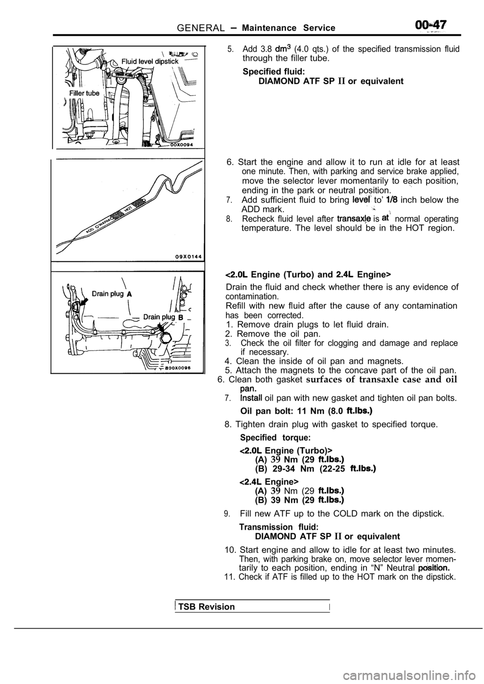
5.Add 3.8 (4.0 qts.) of the specified transmission fluid
through the filler tube.
Specified fluid:DIAMOND ATF SP IIor equivalent
6. Start the engine and allow it to run at idle for at least
one minute. Then, with parking and service brake ap plied,
move the selector lever momentarily to each positio n,
ending in the park or neutral position.
7.Add sufficient fluid to bring to’ inch below the
ADD mark.
8.Recheck fluid level after is normal operating
temperature. The level should be in the HOT region.
Engine (Turbo) and Engine>
Drain the fluid and check whether there is any evid ence of
contamination.
Refill with new fluid after the cause of any contam ination
has been corrected.
1. Remove drain plugs to let fluid drain.
2. Remove the oil pan.
3.Check the oil filter for clogging and damage and re place
if necessary.
4. Clean the inside of oil pan and magnets.
5. Attach the magnets to the concave part of the oi l pan.
6. Clean both gasket surfaces of transaxle case and oil
7. oil pan with new gasket and tighten oil pan bolts.
Oil pan bolt: 11 Nm (8.0
8. Tighten drain plug with gasket to specified torq ue.
Specified torque:
Engine (Turbo)>
(A) 39Nm (29
(B) 29-34 Nm (22-25
Engine>
(A) 39Nm (29
(B) 39 Nm (29
9.Fill new ATF up to the COLD mark on the dipstick.
Transmission fluid:
DIAMOND ATF SP IIor equivalent
10. Start engine and allow to idle for at least two minutes.
Then, with parking brake on, move selector lever mo men-
tarily to each position, ending in “N” Neutral
11. Check if ATF is filled up to the HOT mark on the dipstick.
TSB RevisionI
Page 50 of 2103
GENERAL Maintenance Service
,
Revision
Drain Plug
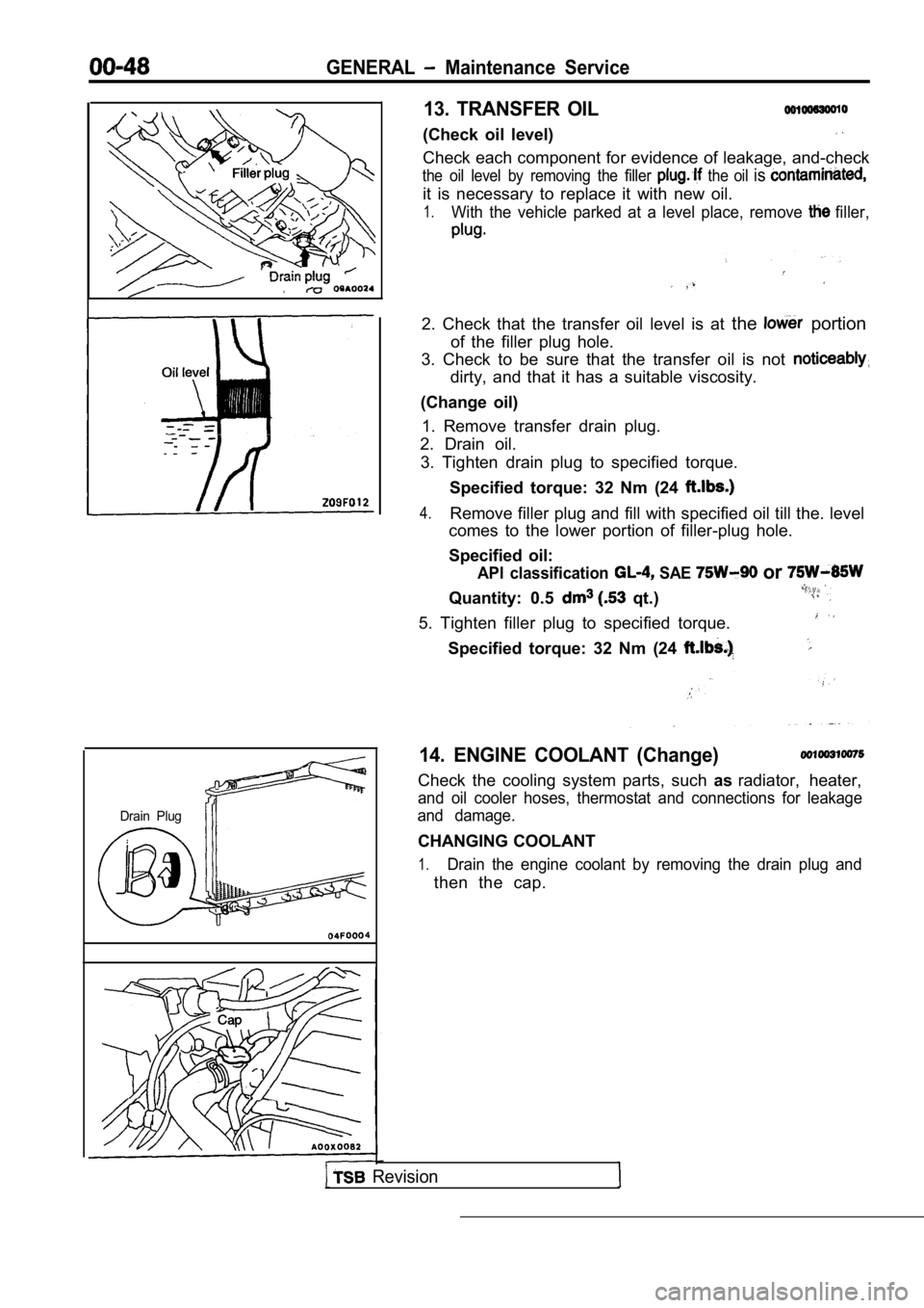
13. TRANSFER OIL
(Check oil level)
Check each component for evidence of leakage, and-check
the oil level by removing the filler the oil is
it is necessary to replace it with new oil.
1.With the vehicle parked at a level place, remove filler,
2. Check that the transfer oil level is at the portion
of the filler plug hole.
3. Check to be sure that the transfer oil is not
dirty, and that it has a suitable viscosity.
(Change oil) 1. Remove transfer drain plug.
2. Drain oil.
3. Tighten drain plug to specified torque.
Specified torque: 32 Nm (24
4.Remove filler plug and fill with specified oil till the. level
comes to the lower portion of filler-plug hole.
Specified oil:
API classification SAE or
Quantity: 0.5 qt.)
5. Tighten filler plug to specified torque.
Specified torque: 32 Nm (24
14. ENGINE COOLANT (Change)
Check the cooling system parts, such asradiator, heater,
and oil cooler hoses, thermostat and connections fo r leakage
and damage.
CHANGING COOLANT
1.Drain the engine coolant by removing the drain plug and
then the cap.
Page 51 of 2103
GENERAL Maintenance
a
Engine (Non-turbo)>
in plug
Engine>
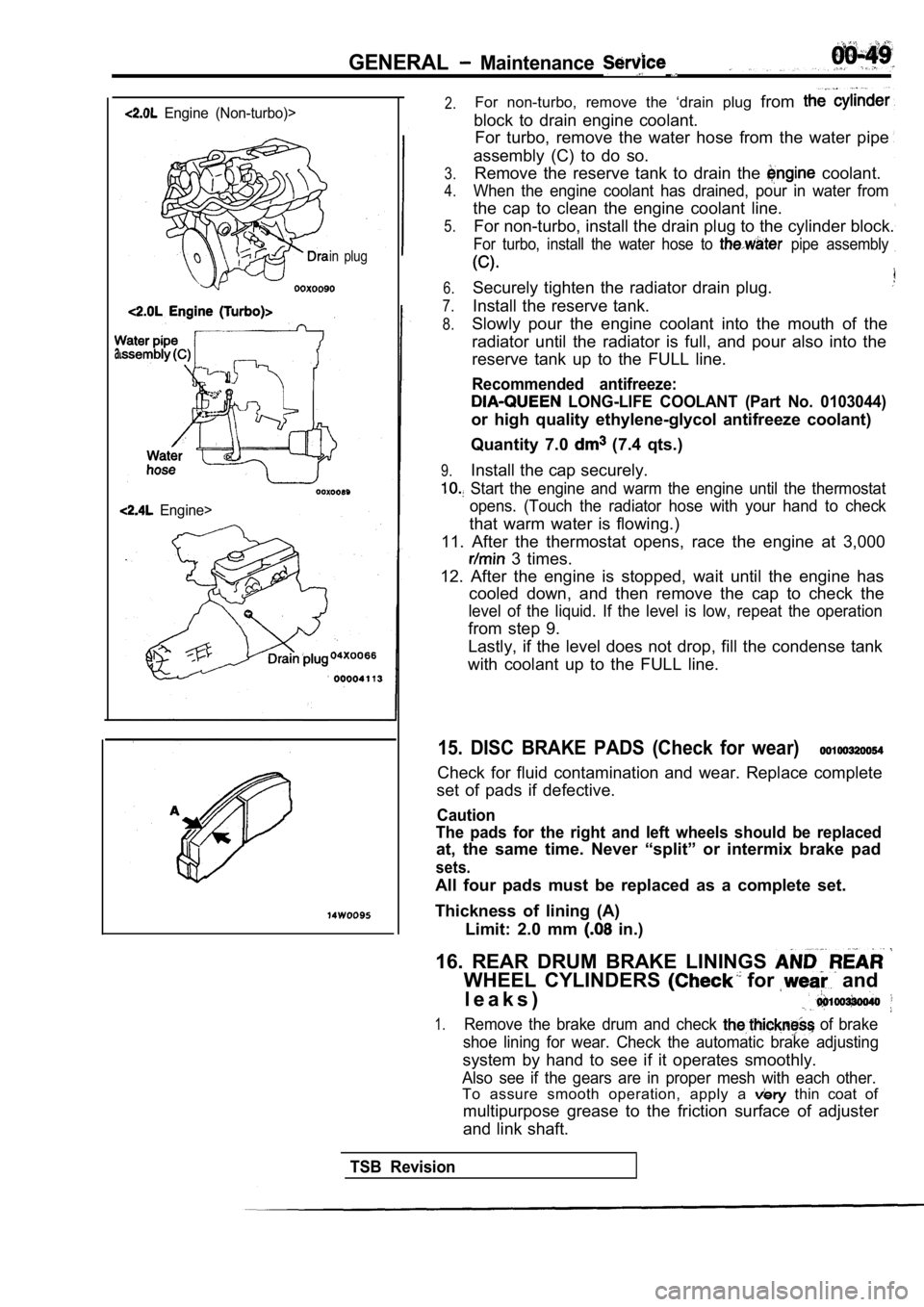
2.For non-turbo, remove the ‘drain plug from
block to drain engine coolant.
For turbo, remove the water hose from the water pip e
assembly (C) to do so.
3.
4.
5.Remove the reserve tank to drain the coolant.
When the engine coolant has drained, pour in water from
the cap to clean the engine coolant line.
For non-turbo, install the drain plug to the cylind er block.
For turbo, install the water hose to pipe assembly
6.
7.
8.
Securely tighten the radiator drain plug.
Install the reserve tank.
9.
Slowly pour the engine coolant into the mouth of th e
radiator until the radiator is full, and pour also into the
reserve tank up to the FULL line.
Recommended antifreeze:
LONG-LIFE COOLANT (Part No. 0103044)
or high quality ethylene-glycol antifreeze coolant)
Quantity 7.0
(7.4 qts.)
Install the cap securely.
Start the engine and warm the engine until the the rmostat
opens. (Touch the radiator hose with your hand to c heck
that warm water is flowing.)
11. After the thermostat opens, race the engine at 3,000
3 times.
12. After the engine is stopped, wait until the eng ine has
cooled down, and then remove the cap to check the
level of the liquid. If the level is low, repeat th e operation
from step 9.
Lastly, if the level does not drop, fill the conden se tank
with coolant up to the FULL line.
15. DISC BRAKE PADS (Check for wear)
Check for fluid contamination and wear. Replace com plete
set of pads if defective.
Caution
The pads for the right and left wheels should be re placed
at, the same time. Never “split” or intermix brake pad
sets.
All four pads must be replaced as a complete set.
Thickness of lining (A) Limit: 2.0 mm
in.)
16. REAR DRUM BRAKE LININGS
WHEEL CYLINDERS for and
l e a k s )
1.Remove the brake drum and check of brake
shoe lining for wear. Check the automatic brake adj usting
system by hand to see if it operates smoothly.
Also see if the gears are in proper mesh with each other.
To assure smooth operation, apply a thin coat of
multipurpose grease to the friction surface of adju ster
and link shaft.
TSB Revision
Page 61 of 2103
ENGINE
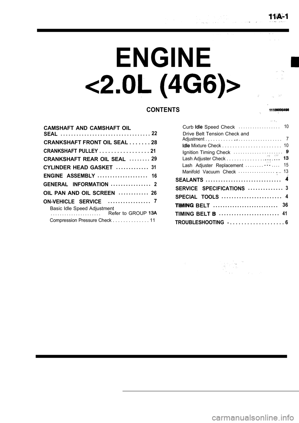
CONTENTS
CAMSHAFT AND CAMSHAFT OIL
SEAL. . . . . . . . . . . . . . . . . . . . . . . . . . . . . . . . . .22
CRANKSHAFT FRONT OIL SEAL . . . . . . . 28
CRANKSHAFT PULLEY . . . . . . . . . . . . . . . . . 21
CRANKSHAFT REAR OIL SEAL. . . . . . . .29
Curb Speed Check. . . . . . . . . . . . . . . . . .10
Drive Belt Tension Check and
Adjustment . , . . . . . . . . . . . . . . . . . . . . . . . . . . . 7
Mixture Check . . . . . . . . . . . . . . . . . .
. . . . .10
Ignition Timing Check. . . . . . . . . . . .. . . . . . . . .
Lash Adjuster Check . . . . . . . . . . . . . . . .
CYLINDER HEAD GASKET . . . . . . . . . . . . .31
ENGINE ASSEMBLY. . . . . . . . . . . . . . . . . . . .16
GENERAL INFORMATION. . . . . . . . . . . . . . . .2
OIL PAN AND OIL SCREEN . . . . . . . . . . . .26
ON-VEHICLE SERVICE. . . . . . . . . . . . . . . . .7
Basic Idle Speed Adjustment
. . . . . . . . . . . . . . . . . . . . . . Refer to GROUP
Lash Adjuster Replacement. . . . . . . .. . . .15
Manifold Vacuum Check. . . . . . . . . . . . . . . ....13
SEALANTS. . . . . . . . . . . . . . . . . . . . . . . . . . . . . .
SERVICE SPECIFICATIONS. . . . . . . . . . . . . .3
SPECIAL TOOLS. . . . . . . . . . . . . . . . . . . . . . . .4
BELT. . . . . . . . . . . . . . . . . . . . . . . . . . .36
TIMING BELT . . . . . . . . . . . . . . . . . . . . . . . .41
Compression Pressure Check . . . . . . . . . . . .
. . 11TROUBLESHOOTING . . . . . . . . . . . . . . . . . . . 6
Page 63 of 2103
ENGINE Service Specifications
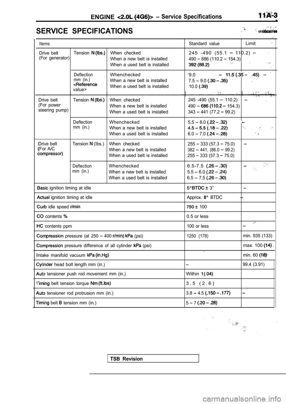
SERVICE SPECIFICATIONS
I
1
Items
Drive beltTensionWhen checked
(For generator) When a new belt is installed
When a used belt is installed
DeflectionWhenchecked
mm (in.)When a new belt is installed
value>When a used belt is installed
Drive belt Tension
When checked
(For power When a new belt is installed
steering pump) When a used belt is installed
DeflectionWhenchecked
mm (in.)When a new belt is installed
When a used belt is installed
Drive belt Tension
(Ibs.) When checked
[For A/C When a new belt is installed
When a used belt is installed
DeflectionWhenchecked
mm (in.)When a new belt is installed
When a used belt is installed
ignition timing at idle
ignition timing at idle
idle speed
contents
contents ppm
pressure (at 250 400 (psi)
pressure difference of all cylinder (psi)
ntake manifold vacuum
head bolt length mm (in.)
tensioner push rod movement mm (in.)
belt tension torque
tensioner rod protrusion mm (in.)
belt tension mm (in.)
Standard valueLimit
2 4 5 - 4 9 0 ( 5 5 . 1 1 1 0 . 2 )
490 886 (110.2 154.3)
‘9.0
7.5 9.0
10.0
.245 -490 (55.1 110.2)
490 154.3)
343
441 (77.2 99.2)
5.5
8.0
6.0 7.0
255 333 (57.3 75.0)
382 441, (86.0 99.2)
255 333 (57.3 75.0)
6 . 5 - 7 . 5
5.5 6.0
6.5 7.5
3”
Approx. BTDC
100
0.5 or less
100 or less
1250 (178)min. 935 (133)
max. 100
min. 60
99.4 (3.91)
Within
3 . 5 ( 2 . 6 )
3.8 4.5
5 7
TSB Revision
Page 66 of 2103
ENGINE,
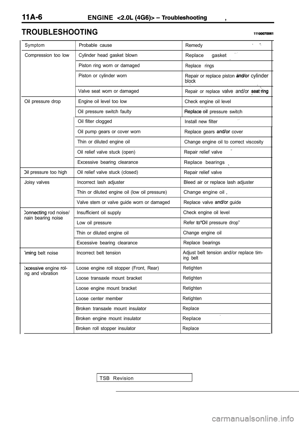
TROUBLESHOOTING
Oil filter cloggedInstall new filter
Oil pump gears or cover wornReplace gears cover
Thin or diluted engine oil Change engine oil to correct viscosity
Oil relief valve stuck (open) Repair relief valve
Excessive bearing clearanceReplace bearings
pressure too high Oil relief valve stuck (closed) Repair relief valve
Joisy valves Incorrect lash adjuster Bleed air or rep lace lash adjuster
Thin or diluted engine oil (low oil pressure)
Change engine oil ,
Valve stem or valve guide worn or damaged Replace va lve guide
rod noise/Insufficient oil supplyCheck engine oil level
nain bearing noise Low oil pressure Refer
pressure drop”
Thin or diluted engine oil Change engine oil
Excessive bearing clearance Replace bearings
belt noiseIncorrect belt tension Adjust belt tension and/or replace tim-ing belt
engine Loose engine roll stopper (Front, Rear)Retighten
ng and vibration
Loose transaxle mount bracketRetighten
Loose engine mount bracketRetighten
Loose center memberRetighten
Broken transaxle mount insulatorReplace
Broken engine mount insulatorReplace
Broken roll stopper insulatorReplace
Symptom
Probable cause
Remedy.
Compression too low Cylinder head gasket blownReplace gasket
Piston ring worn or damagedReplace rings
Piston or cylinder worn
Repair or replace piston cylinder
block
Valve seat worn or damagedRepair or replace valve and/or
Oil pressure drop Engine oil level too low Check engine oil level
Oil pressure switch faulty
pressure switch
TSB Revision
Page 67 of 2103
ENGINE On-vehicle
98 (22
Generator
pulley
pulley
v
pulley
ON-VEHICLE
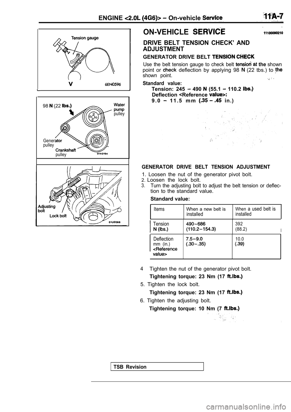
DRIVE BELT TENSION CHECK’ AND
ADJUSTMENT
GENERATOR DRIVE BELT
Use the belt tension gauge to check belt the shown
point or deflection by applying 98 (22 tbs.) to
shown point.
Standard value:
Tension: 245 490 (55.1 110.2
Deflection
GENERATOR DRIVE BELT TENSION ADJUSTMENT
1. Loosen the nut of the generator pivot bolt.
2. Loosen the lock bolt.
3.Turn the adjusting bolt to adjust the belt tension or deflec-
tion to the standard value.
Standard value:
ItemsWhen a new belt is
installed
Whena used belt is
installed
Tension392
(88.2)I
Deflection10.0
mm (in.)
4Tighten the nut of the generator pivot bolt.
Tightening torque: 23 Nm (17
5. Tighten the lock bolt.
Tightening torque: 23 Nm (17
6. Tighten the adjusting bolt.Tightening torque: 10 Nm (7
TSB Revision