Page 84 of 2103

ENGINECamshaft and Camshaft Oil
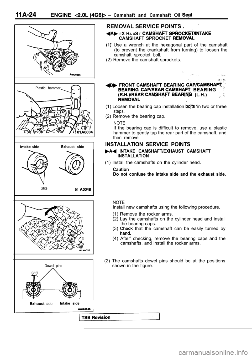
Plastic hammer
sideExhaust side
Slits01
Dowel pins
ExhaustsideIntake side
I
REMOVAL SERVICE POINTS .
EX H A UST
CAMSHAFT SPROCKET
Use a wrench at the hexagonal part of the camshaft
(to prevent the crankshaft from turning) to loosen the
camshaft sprocket bolt.
(2) Remove the camshaft sprockets.
FRONT CAMSHAFT BEARING FRONT CAMSHAFT BEARING
B E A R I N G B E A R I N G
(L.H.) (L.H.)
(1) Loosen the bearing cap installation ‘in two or three
steps.
(2) Remove the bearing cap.
NOTE
If the bearing cap is difficult to remove, use a plastic
hammer to gently tap the rear part of the camshaft, and
then remove.
INSTALLATION SERVICE POINTS
INTAKE CAMSHAFT/EXHAUST CAMSHAFT
INSTALLATION
(1) Install the camshafts on the cylinder head.
Caution
Do not confuse the intake side and the exhaust side .
NOTE
Install new camshafts using the following procedure.
(1) Remove the rocker arms.
(2) Lay the camshafts on the cylinder head and inst all
the bearing caps.
(3)
that the camshaft can be easily turned by
(4) After’ checking, remove the bearing caps and th e
camshafts, and install the rocker arms.
(2) The camshafts dowel pins should be at the posit ions
shown in the figure.
Page 85 of 2103
ENGINECamshaft and Oil Seal
CAMSHAFT CAP
C A M S H A F T
BEARING CAP
INSTALLATION
Tighten the bearing cap installation bolts to the torque
in two or three steps.
C a u t i o n
Tighten uniformly, otherwise the rocker arms not
straight.
Camshaft position
Camshaft positionsensor paint
CAMSHAFT OIL SEAL INSTALLATION
Use the special tool to drive the camshaft oil seal into position
carefully.
CAMSHAFT POSITION SENSING CYLINDER/
CAMSHAFT POSITION SENSOR SUPPORT
INSTALLATION
(1) Install the camshaft position sensing cylinder to the end
of the camshaft as shown in the illustration.
(2) Install the camshaft position sensor support.
(3)Check that the identification paint on the
sensing cylinder is pointing in the same direction as the,
camshaft position sensor installation direction when
camshaft is at the No. 1 compression TDC position.
TSB Revision
Page 94 of 2103
ENGINE H e a d
I n t a k e s i d eFront of
enaine
Exhaust side
Step 4
I
Painted marks
Step 5
Painted marks
Thermostat case assembly orwater pump
Water inlet pipe assembly
(3) bolts by the f o l l o w i n g
Step
Tighten to
78
(58
Remarks
In the in the
2 Loosen In order of that
3Tighten to
20 Nm (15
4Tighten of a turn.In the order-shown in-the
. illustration; Mark
of the cylinder head bolt
and cylinder head by
paint. ,
5
Tighten of a turn. shown in the
Check that the
painted
of
. lined
the
Caution
1.Always make a tightening If
than the head bolt will loosened.
2.If it is more than remove the head bolt repeat
the procedure 1. ,
the O-ring to the water inlet pipe,and coat the outer
inside diameter
the O-ring with water or coolant.
Caution
Do not let engine oil or other greases contact
O-ring.
TH E R M OSTAT CASE AS S E M B L Y
(1) Loosen the water inlet pipe bolt shown in
TSB Revision
Page 98 of 2103

ENGINE Timing Belt
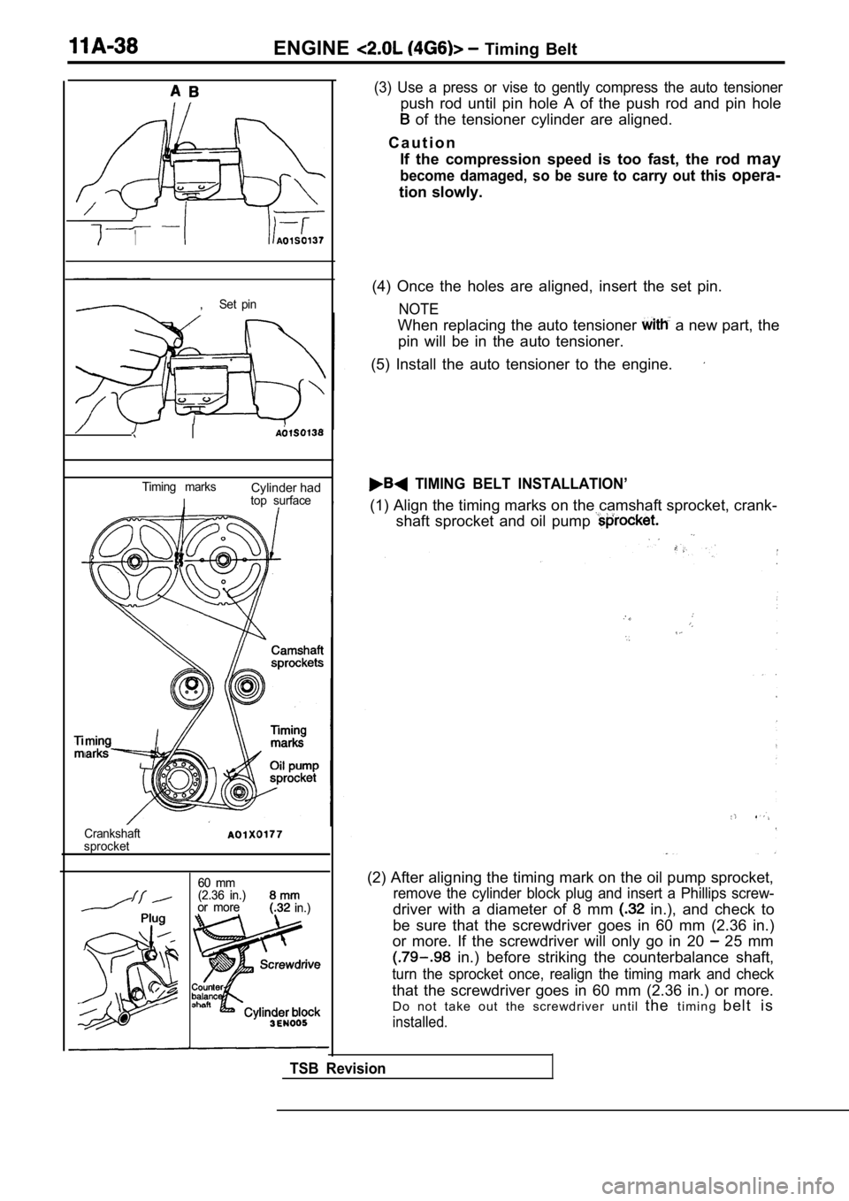
,Set pin
I
Timing marksCylinder had
Itop surface
Crankshaft
sprocket
60 mm
60 mm
(2.36 in.)
(2.36 in.)
or more
or more in.) in.)
(3) Use a press or vise to gently compress the auto tensioner
push rod until pin hole A of the push rod and pin hole
of the tensioner cylinder are aligned.
C a u t i o n If the compression speed is too fast, the rod may
become damaged, so be sure to carry out this opera-
tion slowly.
(4) Once the holes are aligned, insert the set pin.
NOTE
When replacing the auto tensioner a new part, the
pin will be in the auto tensioner.
(5) Install the auto tensioner to the engine.
TIMING BELT INSTALLATION’
(1) Align the timing marks on the camshaft sprocket , crank-
shaft sprocket and oil pump
(2) After aligning the timing mark on the oil pump sprocket,
remove the cylinder block plug and insert a Phillips screw-
driver with a diameter of 8 mm in.), and check to
be sure that the screwdriver goes in 60 mm (2.36 in .)
or more. If the screwdriver will only go in 20
25 mm
in.) before striking the counterbalance shaft,
turn the sprocket once, realign the timing mark and check
that the screwdriver goes in 60 mm (2.36 in.) or mo re.
Do not take out the screwdriver until thet i m i n g b e l t i s
installed.
TSB Revision
Page 102 of 2103

ENGINE Timing Belt
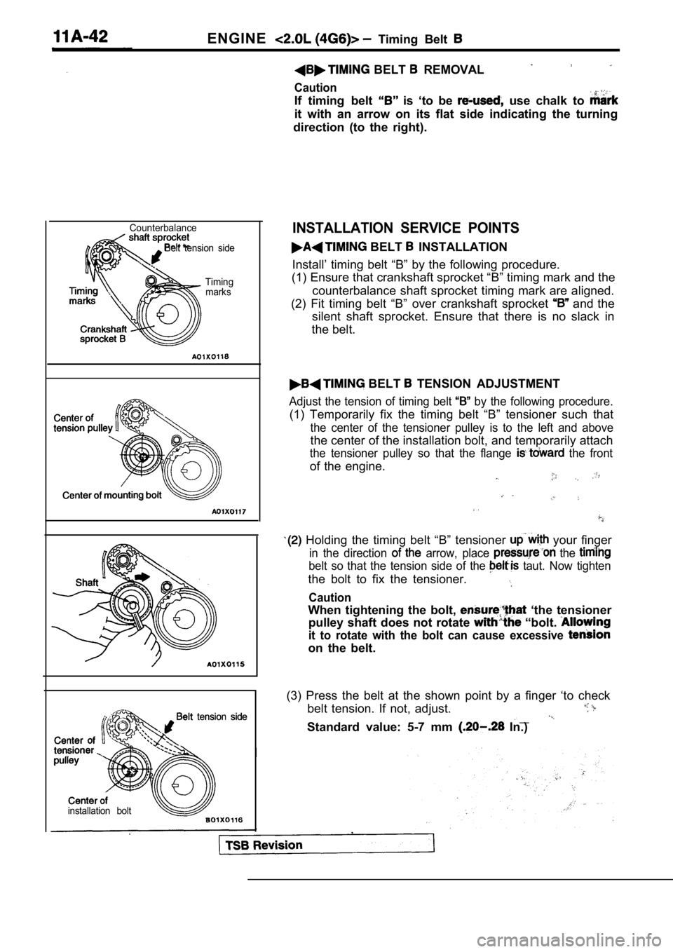
CounterbalanceBelt tension side
Timingmarks
Belt tension side tension side
installation bolt
BELT REMOVAL
Caution
If timing belt is ‘to be use chalk to
it with an arrow on its flat side indicating the tu rning
direction (to the right).
INSTALLATION SERVICE POINTS
BELT INSTALLATION
Install’ timing belt “B” by the following procedure .
(1) Ensure that crankshaft sprocket “B” timing mark and the
counterbalance shaft sprocket timing mark are align ed.
(2) Fit timing belt “B” over crankshaft sprocket
and the
silent shaft sprocket. Ensure that there is no slac k in
the belt.
BELT TENSION ADJUSTMENT
Adjust the tension of timing belt by the following procedure.
(1) Temporarily fix the timing belt “B” tensioner s uch that
the center of the tensioner pulley is to the left and above
the center of the installation bolt, and temporarily attach
the tensioner pulley so that the flange the front
of the engine.
Holding the timing belt “B” tensioner your finger
in the direction arrow, place the
belt so that the tension side of the taut. Now tighten
the bolt to fix the tensioner.
Caution
When tightening the bolt, ‘the tensioner
pulley shaft does not rotate
“bolt.
it to rotate with the bolt can cause excessive
on the belt.
(3) Press the belt at the shown point by a finger ‘ to check
belt tension. If not, adjust.
__Standard value: 5-7 mm In.)
Page 122 of 2103

ENGINE OVERHAUL Timing’
COUNTERBALANCE SHAFT
INSTALLATION
BELT “B” INSTALLATION
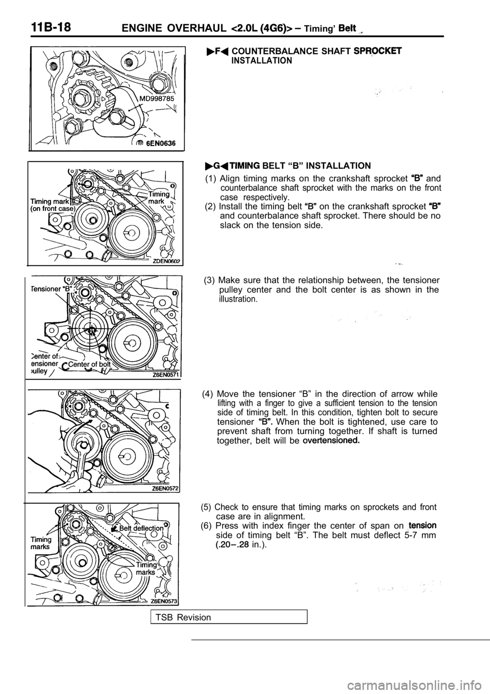
(1) Align timing marks on the crankshaft sprocket
and
counterbalance shaft sprocket with the marks on the front
case respectively.
(2) Install the timing belt on the crankshaft sprocket
and counterbalance shaft sprocket. There should be no
slack on the tension side.
(3) Make sure that the relationship between, the te nsioner
pulley center and the bolt center is as shown in th e
illustration.
(4) Move the tensioner “B” in the direction of arrow while
lifting with a finger to give a sufficient tension to the tension
side of timing belt. In this condition, tighten bolt to secure
tensioner When the bolt is tightened, use care to
prevent shaft from turning together. If shaft is tu rned
together, belt will be
(5) Check to ensure that timing marks on sprockets and front
case are in alignment.
(6) Press with index finger the center of span on
side of timing belt “B”. The belt must deflect 5-7 mm
in.).
TSB Revision
Page 125 of 2103
ENGINE OVERHAUL Belt
Phillips screwdriver
TSBRevision
(4) a Phillips screwdriver [shank diameter 8 mm
in.)] through the hole.
If it can be inserted as deep as 60 mm (2.4 or more;
the timing ‘marks are correctly aligned. If the inserted
depth is only
mm in.), turn the oil’ pump
sprocket one turn and
marks. Then check
to ensure that the screwdriver can be inserted 60 m m
(2.4 in.) or more. Keep the screwdriver inserted the
installation of the timing belt is finished.
NOTE
Step (4) is performed to ensure that the oil pump sprocket
is correctly positioned with reference to the counterbal-
ance shafts.
(5) Thread the timing belt over the intake side cam shaft
sprocket and fix it at indicated position by a bulldog clip.
(6) Thread the timing belt over the exhaust side sp rocket,
aligning the timing marks with the cylinder head top surface
using two wrenches.
(7) Fix the belt at indicated, position
a bulldog clip.
Page 127 of 2103
ENGINE OVERHAUL Timing
Cracks’
Rounded edgeI
Abnormal wear(Fluffy strand)
Rubber exposed
Tooth missingand canvas fibe
INSPECTION
TIMING BELT
Replace belt if any of the following conditions exi st.
(1) Hardening of back rubber.
Back side is glossy without resilience and leaves no indent
when pressed with fingernail.
(2) Cracks on rubber back.
(3) Cracks or peeling of canvas.
(4) Cracks on rib root.
(5) Cracks on belt sides.
(6) Abnormal wear of belt sides. The sides are norm al if
they are sharp as if cut by a knife.
(7) Abnormal wear on teeth.
(8) Missing tooth.
AUTO TENSIONER
(1) Check the auto tensioner for possible leaks and replace
as necessary.
(2) Check the rod end for wear or damage and replac e as
necessary.
(3) Measure the rod protrusion. If it is out of specification,
replace the auto tensioner.
Standard value: 12 mm
in.)