Page 206 of 2103
ENGINE Belt
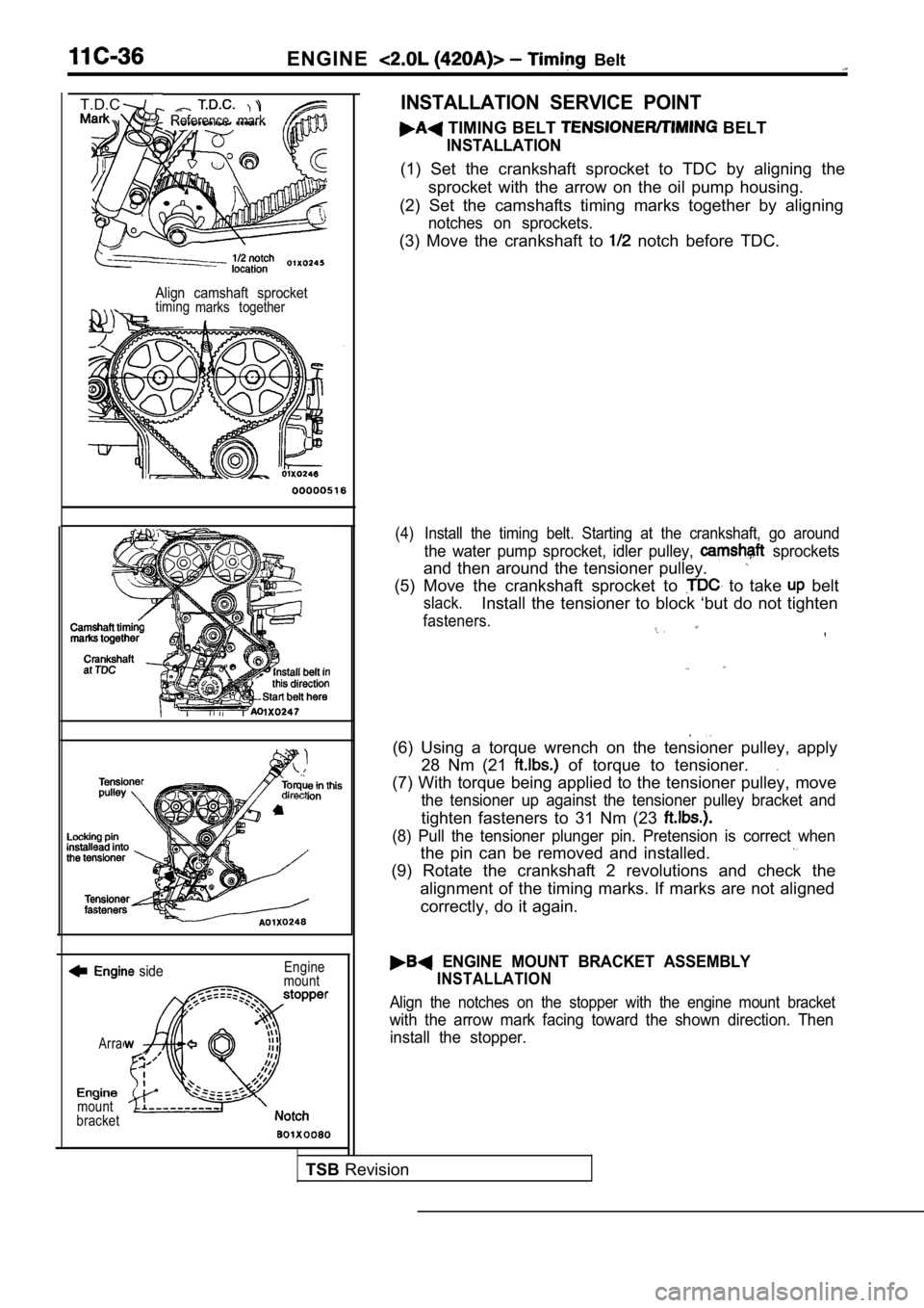
Reference mark
T.D.C.
Align camshaft sprockettimingmarks together
side
Arra
mount
bracket Engine
mount
INSTALLATION SERVICE POINT
TIMING BELT BELT
INSTALLATION
(1) Set the crankshaft sprocket to TDC by aligning the
sprocket with the arrow on the oil pump housing.
(2) Set the camshafts timing marks together by alig ning
notches on sprockets.
(3) Move the crankshaft to notch before TDC.
(4) Install the timing belt. Starting at the crankshaft, go around
the water pump sprocket, idler pulley, sprockets
and then around the tensioner pulley.
(5) Move the crankshaft sprocket to to take belt
slack.Install the tensioner to block ‘but do not tighten
fasteners.
(6) Using a torque wrench on the tensioner pulley, apply
28 Nm (21
of torque to tensioner..
(7) With torque being applied to the tensioner pull ey, move
the tensioner up against the tensioner pulley brack et and
tighten fasteners to 31 Nm (23
(8) Pull the tensioner plunger pin. Pretension is correct when
the pin can be removed and installed.
(9) Rotate the crankshaft 2 revolutions and check t he
alignment of the timing marks. If marks are not ali gned
correctly, do it again.
ENGINE MOUNT BRACKET ASSEMBLY
INSTALLATION
Align the notches on the stopper with the engine mo unt bracket
with the arrow mark facing toward the shown direction. Then
install the stopper.
TSB Revision
Page 225 of 2103
ENGINE OVERHAUL Belt
TDCInstall belt in
‘this
here
belt. Starting at the crankshaft, go around
the water pump sprocket, ‘idler pulley,
and then around the tensioner pulley.
crankshaft sprocket to up belt slack.
Install tensioner to block but do not tighten faste ners.
a torque wrench on the tensioner pulley, apply
28 Nm (20
of torque to tensioner.
torque being applied to the tensioner pulley move
the tensioner up against the tensioner pulley
tighten fasteners to 31 Nm (22
tensioner plunger pin,Pretension is correct when
pin can be removed and installed.
crankshaft 2 revolutions and check the alignment
of the timing marks.
front timing belt cover.
Timing Check; (timing belt cover installed), remov e
the inspection cover on timing belt cover. With num ber
one cylinder at TDC, the timing marks on the camsha ft
sprocket should be aligned together. If marks are n ot
aligned correctly, perform procedure again.
Revision
Page 228 of 2103
11 ENGINE OVERHAUL Cooling System
(1) Install switch.
(2) Install engine coolant
lighten sensor
to 7 Nm (5
torque.
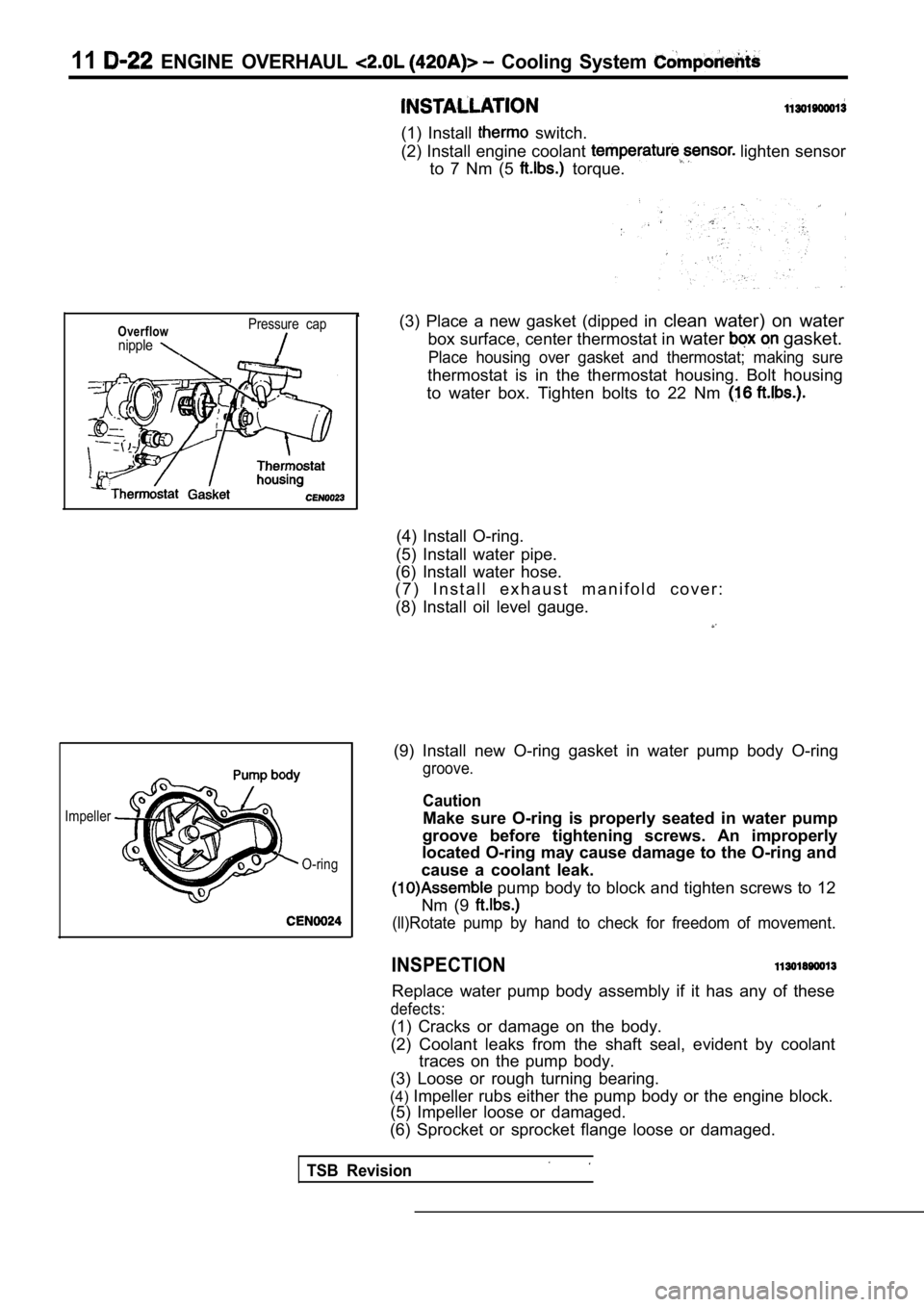
Overflownipple
Pressure cap
Impeller
TSB Revision
O-ring
(3) Place a new gasket (dipped in clean water) on water
box surface, center thermostat in water
gasket.
Place housing over gasket and thermostat; making su re
thermostat is in the thermostat housing. Bolt housing
to water box. Tighten bolts to 22 Nm
(4) Install O-ring.
(5) Install water pipe.
(6) Install water hose.
( 7 ) I n s t a l l e x h a u s t m a n i f o l d c o v e r :
(8) Install oil level gauge.
(9) Install new O-ring gasket in water pump body O- ring
groove.
Caution
Make sure O-ring is properly seated in water pump
groove before tightening screws. An improperly
located O-ring may cause damage to the O-ring and
cause a coolant leak.
pump body to block and tighten screws to 12
Nm (9
(ll)Rotate pump by hand to check for freedom of mov ement.
INSPECTION
Replace water pump body assembly if it has any of these
defects:
(1) Cracks or damage on the body.
(2) Coolant leaks from the shaft seal, evident by c oolant
traces on the pump body.
(3) Loose or rough turning bearing.
(4) Impeller rubs either the pump body or the engine bl ock.
(5) Impeller loose or damaged.
(6) Sprocket or sprocket flange loose or damaged.
Page 237 of 2103
(1) Inspect camshaft bearing journals for damage and bind-
ing.
If journals are binding, also check the cylinder head bear-
ing surface for damage, and check the camshaft bearing
oil feed holes in the cylinder head for clogging.
(2) Check the cam surface for abnormal wear and damage.
Replace if defective. Also measure the cam height and
replace if out of limit.
Standard value: 0.0254 mm
in.)
Limit: 0.254 mm in.)
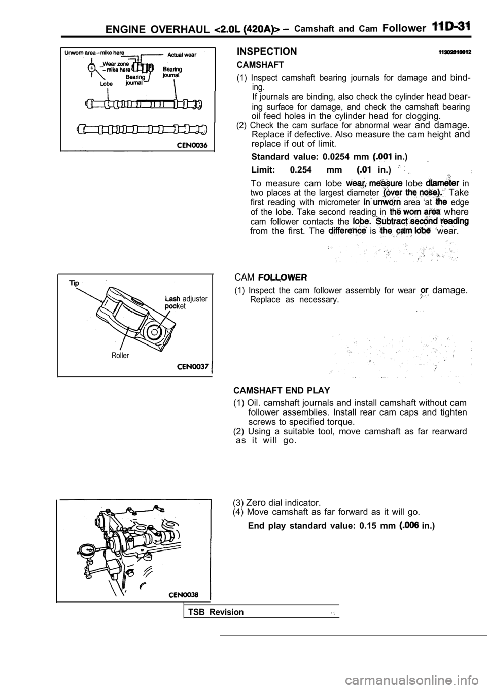
To measure cam lobe lobe in
two places at the largest diameter Take
first reading with micrometer area ‘at edge
of the lobe. Take second reading in
where
cam follower contacts the
from the first. The is ‘wear.
ENGINE OVERHAUL Camshaft and Cam Follower
INSPECTION
CAMSHAFT
adjusterket
Roller
CAM
(1) Inspect the cam follower assembly for wear damage.
Replace as necessary.
CAMSHAFT END PLAY
(1) Oil. camshaft journals and install camshaft wit hout cam
follower assemblies. Install rear cam caps and tigh ten
screws to specified torque.
(2) Using a suitable tool, move camshaft as far rea rward
a s i t w i l l g o .
(3) Zero dial indicator.
(4) Move camshaft as far forward as it will go.
End play standard value: 0.15 mm
in.)
TSB Revision
Page 244 of 2103
11ENGINE OVERHAUL Cylinder Head
(6) seat is properly positioned, the width of intake
and exhaust seats should be 0.9 to 1.3 mm
to
in.).
(7) Check valve tip to spring seat dimensions A aft er grinding
the valve seats or faces. Grind valve tip until
A is equal to 47.99 mm (1.889 in.) for exhaust valv e
and 48.04 mm (1.891 in.) for intake valve over spri ng
seat when installed in the head.
The valve tip chamfer may need to be reground to pr event
seal damage when the valve is installed.
(8)
the valve spring installed height after refacing
the valve and seat. Make sure measurements are take n
from top of spring seat to the bottom surface of spring
retainer.
If is greater than 38.00 mm (1.496 in.), install a
0.762 mm
in.) spacer in head counterbore under
the valve spring seat to bring spring height back w ithin
specification.
RevisionI
Page 258 of 2103
11
Piston, Connecting Rod
ENGINE OVERHAUL and
INSPECTION
BLOCK
(1) Clean cylinder block thoroughly and check all core hole
plugs for evidence of leaking.
(2) Examine block and cylinder bores for cracks or fractures.
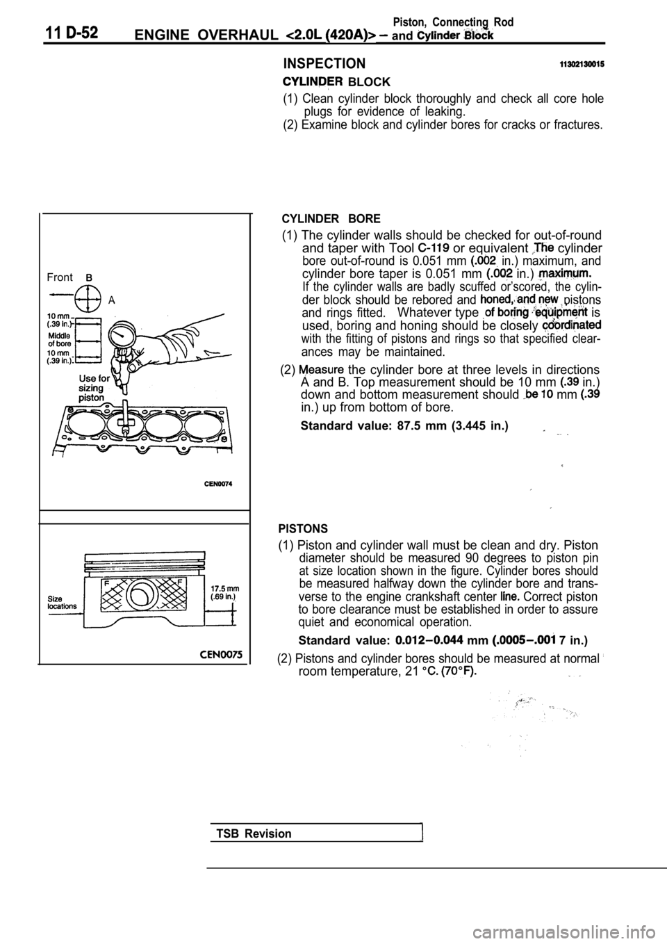
Front
A
CYLINDER BORE
(1) The cylinder walls should be checked for out-of-round
and taper with Tool or equivalent cylinder
bore out-of-round is 0.051 mm in.) maximum, and
cylinder bore taper is 0.051 mm in.)
If the cylinder walls are badly scuffed or’scored, the cylin-
der block should be rebored and pistons
and rings fitted.
Whatever type is
used, boring and honing should be closely
with the fitting of pistons and rings so that speci fied clear-
ances may be maintained.
(2) the cylinder bore at three levels in directions
A and B. Top measurement should be 10 mm
in.)
down and bottom measurement should
mm
in.) up from bottom of bore.
Standard value: 87.5 mm (3.445 in.)
PISTONS
(1) Piston and cylinder wall must be clean and dry. Piston
diameter should be measured 90 degrees to piston pi n
at size location shown in the figure. Cylinder bores should
be measured halfway down the cylinder bore and tran s-
verse to the engine crankshaft center
Correct piston
to bore clearance must be established in order to a ssure
quiet and economical operation.
Standard value: mm 7 in.)
(2) Pistons and cylinder bores should be measured a t normal
room temperature, 21
TSB Revision
Page 260 of 2103
piston,
ENGINE OVERHAUL Cylinder Block
CONNECTING BEARING
(1) Place a piece of Plastigage across the, width of
bearing in the cap 6.35
mm off center and away -from the hole.
suspect areas can be checked, by placing in
the suspect area.
(2) Before assembling the rod with in place;
‘the crankshaft must be rotated the connecting rod
being checked starts moving toward the top of the e ngine.,
Only then should the cap be and torqued
to the specification.
Do not rotate the crankshaft while assembling the cap
or the Plastigage may be smeared, giving inaccurate re-
sults.
(3) Remove the bearing cap and compare the width of the
flattened Plastigage with the metric scale provided on
the package.
Standard value: mm in.)
Limit: 0.075 mm
in.)
bolt
Threads are not straight on line
Threads are straight
line,
bolt
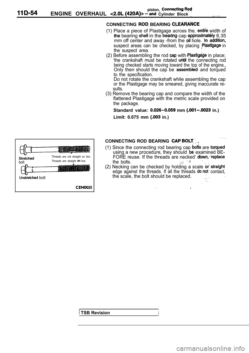
CONNECTING ROD BEARING ,
(1) Since the connecting rod bearing cap are
using a new procedure, they should examined BE-
FORE reuse. If the threads are necked’
the bolts.
(2) Necking can be checked by holding a scale
edge against the threads. If all the threads contact,
the scale, the bolt should be replaced. .
,
TSB RevisionI
Page 266 of 2103
11E N G I N E. .
INSPECTION
CRANKSHAFT MAIN JOURNALS
The crankshaft journals should be checked for excessive
wear, taper and scoring. Limits of taper or
on any crankshaft journals should be held. to mm.
in.). Journal grinding should not exceed 0.305 mm
in.) under the standard Do NOT
grind thrust faces of 3 journal. Do NOT
nick crank pin or journal fillets. After grinding, remove
rough edges from crankshaft oil holes and clean out all
passages.,
Caution.
With the nodular cast iron
tant that the final paper or journal
regrind be in the same direction as normal rotation’
in the engine.
TSB Revision