1990 MITSUBISHI SPYDER check engine
[x] Cancel search: check enginePage 278 of 2103
ENGINE O n - v e h i c l e
Press the scan tool clear key (select aforced driving
cancel mode) to release the ACTUATOR TEST
NOTE
If the test is not a forced driving will continue
for 27 minutes. Driving under this condition may damage
the engine.
Check that the actual ignition timing is at the st andard
value.
Standard value: Approx. BTDC
NOTE
Ignition timing is variable within about even under
normal operating.
2. And it is automatically further advanced by abou t
from BTDC at higher altitudes.
CURB IDLE SPEED CHECK
Before inspection and adjustment, set vehicles in the
following condition.
lEngine coolant temperature:
lLights, electric cooling fan and all accessories: OFF
lTransaxle: Neutral (P range on vehicles with A/T)
2. Turn the ignition switch to OFF and connect the scan
tool to the data link connector.
3. Select No. 17 of the SCAN TOOL ACTUATOR TEST
4. Check the basic ignition timing.
Standard value: BTDC
5. Run the engine at idle for 2 minutes.
6. Select No. 22 of the SCAN TOOL DATA LIST.
7. Check the curb idle speed.
Standard value: 750 100
NOTE
The idle speed is controlled automatically by the i dle air
control system.
8. If the idle speed is outside the standard value, check
the components by referring to GROUP Trou-
bleshooting.
IDLE MIXTURE CHECK
Before inspection, set vehicles in the following co ndition:
lEngine coolant temperature:
lLights, electric cooling fan and all accessories: O FF
lTransaxle: Neutral (P range on vehicles with
2. Turn the ignition switch to OFF and connect the scan
tool to the data link connector.
3. Select No. 17 of the SCAN TOOL ACTUATOR TEST.
4.Check that the basic ignition timing is within the standard
value..
Standard value:
TSB Revision
Page 279 of 2103

On-vehicle
Run the engine.
8. Set CO, HC tester.
7. Check the CO contents and the HC contents at idle.
Standard value:
CO contents: 0.5% or less
HC contents: 100 ppm or less
8. the standard value is exceeded, check the following
items:
l Diagnostic output
l Closed-loop control (When the closed-loop control
is carried out normally, the output signal of the heated
oxygen sensor and
at idle.)
l
Injector
lIgnition coil, spark plug
l system the
l Evaporative emission
Compression ,
NOTE,
Replace the three-way CO and
HC contents do not
the value.
(even though the
of the” on
all items.)
PRESSURE CHECK
1.Before inspection, check that the engine oil, start er and
battery are normal. Also, set the vehicle to the fo llowing
condition:
lEngine coolant temperature:
lLights, electric cooling fan and all accessories: O FF
lTransaxle: Neutral (P range on vehicles with
2. Disconnect the spark plug cables.
3. Remove all of the spark plugs.
4. Disconnect the crankshaft position sensor
NOTE
Doing this will prevent the engine control unit fro m carrying
out ignition and fuel injection.
TSB Revision
Page 280 of 2103
ENGINEOn-vehicle
5. Cover the spark plug hole with a shop towel etc., and
after the engine has been cranked, check that no foreign
material is adhering to the shop towel.
Caution
1.Keep away from the spark plug hole when crank-
ing.
2. If compression is measured with water, fuel,
etc., that has come from cracks inside the
these materials will become heated and gush
out from the spark plug hole, which is dangerous.
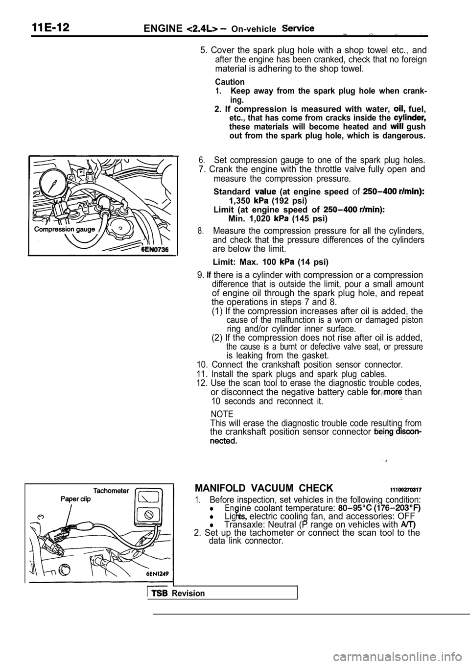
6.Set compression gauge to one of the spark plug hole s.
7. Crank the engine with the throttle valve fully open and
measure the compression pressure.
Standard (at engine speed of
1,350 (192 psi)
Limit (at engine speed of
Min. 1,020 (145 psi)
8.Measure the compression pressure for all the cylind ers,
and check that the pressure differences of the cyli nders
are below the limit.
Limit: Max. 100 (14 psi)
9. there is a cylinder with compression or a compression
difference that is outside the limit, pour a small amount
of engine oil through the spark plug hole, and repe at
the operations in steps 7 and 8.
(1) If the compression increases after oil is added , the
cause of the malfunction is a worn or damaged pisto n
ring and/or cylinder inner surface.
(2) If the compression does not rise after oil is added,
the cause is a burnt or defective valve seat, or pr essure
is leaking from the gasket.
10. Connect the crankshaft position sensor connecto r.
11. Install the spark plugs and spark plug cables.
12. Use the scan tool to erase the diagnostic troub le codes,
or disconnect the negative battery cable than
10 seconds and reconnect it.
NOTE
This will erase the diagnostic trouble code resulting from
the crankshaft position sensor connector
MANIFOLD VACUUM CHECK
1.Before inspection, set vehicles in the following co ndition:
lEn
lLig electric cooling fan, and accessories: OFF
ine coolant temperature:
lTransaxle: Neutral (P range on vehicles with
2. Set up the tachometer or connect the scan tool t o the
data link connector.
Revision
Page 281 of 2103
ENGINE On-vehicle Service’
Highpressurechamber
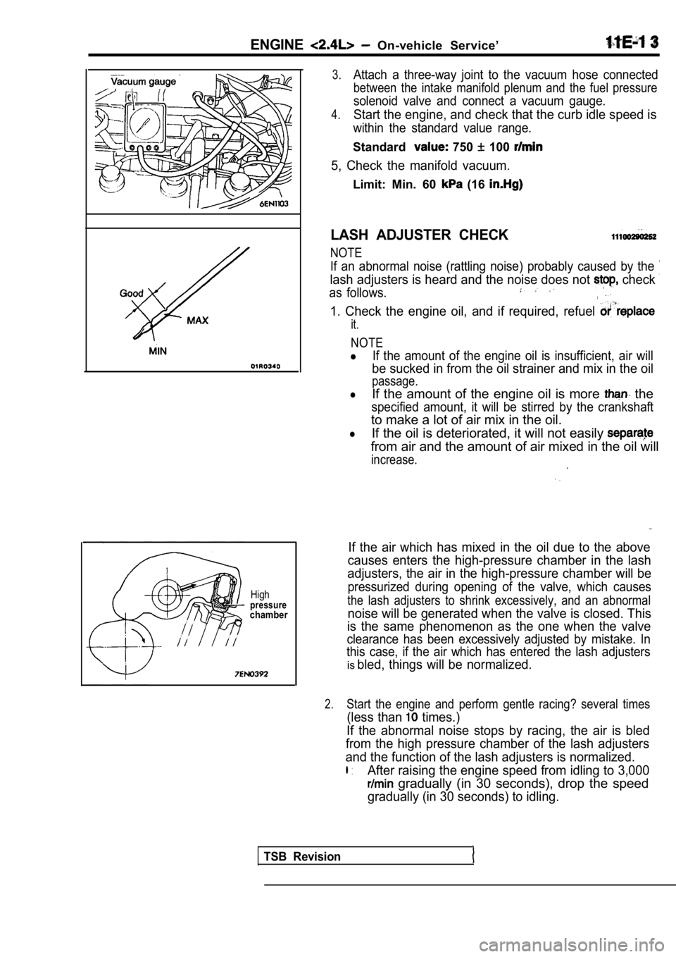
3.Attach a three-way joint to the vacuum hose connected
between the intake manifold plenum and the fuel pressure
solenoid valve and connect a vacuum gauge.
4.Start the engine, and check that the curb idle speed is
within the standard value range.
Standard 750 100
5, Check the manifold vacuum.
Limit: Min. 60 (16
LASH ADJUSTER CHECK
NOTE
If an abnormal noise (rattling noise) probably caus ed by the
lash adjusters is heard and the noise does not check
as follows.
1. Check the engine oil, and if required, refuel
it.
NOTE
lIf the amount of the engine oil is insufficient, air will
be sucked in from the oil strainer and mix in the o il
passage.
lIf the amount of the engine oil is more the
specified amount, it will be stirred by the cranksh aft
to make a lot of air mix in the oil.
lIf the oil is deteriorated, it will not easily
from air and the amount of air mixed in the oil will
increase.
If the air which has mixed in the oil due to the ab ove
causes enters the high-pressure chamber in the lash
adjusters, the air in the high-pressure chamber wil l be
pressurized during opening of the valve, which caus es
the lash adjusters to shrink excessively, and an abnormal
noise will be generated when the valve is closed. This
is the same phenomenon as the one when the valve
clearance has been excessively adjusted by mistake. In
this case, if the air which has entered the lash ad justers
isbled, things will be normalized.
2.Start the engine and perform gentle racing? several times
(less than times.)
If the abnormal noise stops by racing, the air is b led
from the high pressure chamber of the lash adjuster s
and the function of the lash adjusters is normalize d.
l :After raising the engine speed from idling to 3,000
gradually (in 30 seconds), drop the speed
gradually (in 30 seconds) to idling.
TSB Revision
Page 282 of 2103

ENGINE On-vehicle
NOTE
lIf the vehicle is parked on a slope for long, oil
in the lash adjusters will
and ‘air may
enter the high-pressure’ chamber when the vehicle
i s s t a r t e d .
lAfter the vehicle is parked for long, air may enter the high-pressure
because, the oil in the
oil passage will be gone it take a time before
the oil is supplied to the
3.If an abnormal noise does not stop by racing, check the
lash adjusters according to the following procedure s.
Stop the enaine.
of the engine to the compression
top dead center.
(3) Push the rocker arm indicated by the white arrow
mark as shown in the illustration at left and check
whether or not the arm lock goes down.
(4) Turn slowly the crankshaft
clockwise.
(5) Check the rocker arm indicated by the black arr ow
mark as shown in the illustration at left same as above
(3).(6) If the rocker arm can be lowered easily when th e
part of the rocker arm which is directly above the
top of the lash adjuster is pressed, the lash adjus ter
is defective and should be replaced with a new part .
Furthermore, when replacing the lash adjuster, blee d
all of the air from the lash adjuster and then install.
After this, check that there is no problem by check ing
in steps to (5).
NOTE
lA leak-down test can be carried out to accurately
determine whether the lash adjuster is defective
or not.
lFor the procedures for the leak-down test and
air bleeding of the lash adjuster, refer to 11
Furthermore, if the arm feels extremely stiff
and cannot be lowered when it is
the lash
adjuster is normal, so some other cause
of the abnormality.
TSBRevision
Page 286 of 2103
REMOVAL SERVICE POINTS
POWER STEERING PUMP REMOVAL
power steering pump from the bracket with the
hose attached.
NOTE
Place the removed power steering pump in a place wh ere
will not be a hindrance when removing and installing the
engine assembly, and tie it with a cord.
A/C COMPRESSOR REMOVAL
Disconnect the compressor connector and remove the
compressor from the compressor bracket with the hos e still
a t t a c h e d .
NOTE:
Place the removed A/C compressor in a place where i t will
not be
hindrance when removing and installing the engine
assembly, and tie it with a cord.
Do not bend the joint between hose and the A/C
pipe
force.
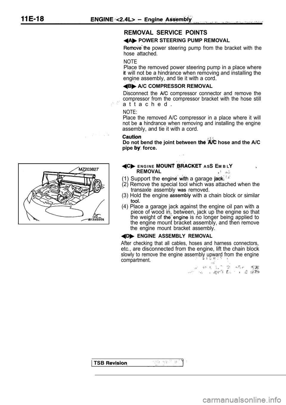
E N G I N E A S S E M B L Y
REMOVAL,
(1) Support the a garage
(2) Remove the special tool which was attached when the
transaxle assembly removed.
(3) Hold the engine with a chain block or similar
(4) Place a garage jack against the engine oil pan with a
piece of wood in, between, jack up the engine so th at
the weight of
is no longer being applied to
the engine mount bracket assembly, and then remove
the engine mount bracket assembly.
ENGINE ASSEMBLY REMOVAL
After checking that all cables, hoses and harness c onnectors,
etc., are disconnected from the engine, lift the chain block
slowly to remove the engine assembly upward from th e engine
compartment.
,
TSB
Page 287 of 2103
Engine Assembly
I N S T A L L A T I O N
ENGINE INSTALLATION
Install the engine while checking
hoses, and harness connectors are not clamped.
MOUNT BRACKET ASSEMBLY
I N S T A L L A T I O N
(1) Place a garage jack against the engine oil pan a
piece of wood in between, and install the engine mo unt
bracket assembly while adjusting the position of th e
en-
gine.
(2) Support the engine with the garage jack.
(3)Remove the chain block and support the engine assem bly
with the special tool.
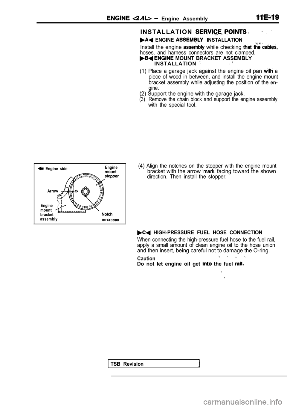
Engine sideEngine
Arro
Engine
mount
bracket(4) Align the notches on the stopper with the engin e mount
bracket with the arrow facing toward the shown
direction. Then install the stopper.
assembly
HIGH-PRESSURE FUEL HOSE CONNECTION
When connecting the high-pressure fuel hose to the fuel rail,
apply a small amount of clean engine oil to the hos e union
and then insert, being careful not to damage the O-ring.
Caution
Do not let engine oil get the fuel
.
TSB Revision
Page 305 of 2103
E N G I N E Timing Belt
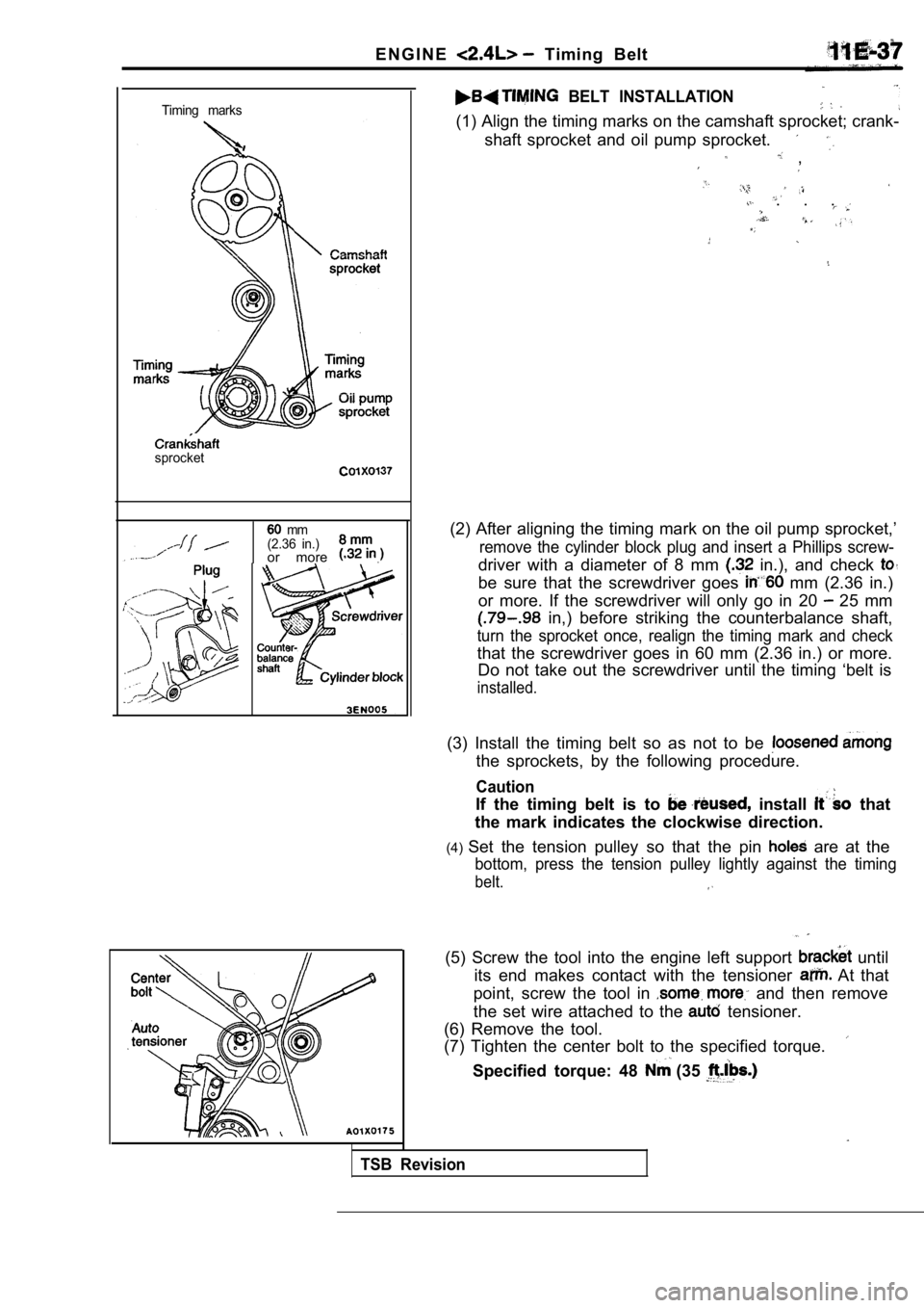
Timing marks
sprocket
mm
(2.36 in.)
or more .
BELT INSTALLATION
(1) Align the timing marks on the camshaft sprocket ; crank-
shaft sprocket and oil pump sprocket.
,
. . .
(2) After aligning the timing mark on the oil pump sprocket,’
remove the cylinder block plug and insert a Phillips screw-
driver with a diameter of 8 mm in.), and check
be sure that the screwdriver goes mm (2.36 in.)
or more. If the screwdriver will only go in 20
25 mm
in,) before striking the counterbalance shaft,
turn the sprocket once, realign the timing mark and check
that the screwdriver goes in 60 mm (2.36 in.) or mo re.
Do not take out the screwdriver until the timing ‘b elt is
installed.
(3) Install the timing belt so as not to be
the sprockets, by the following procedure.
Caution
If the timing belt is to install that
the mark indicates the clockwise direction.
(4) Set the tension pulley so that the pin
are at the
bottom, press the tension pulley lightly against th e timing
belt.
TSB Revision
(5) Screw the tool into the engine left support until
its end makes contact with the tensioner
At that
point, screw the tool in
and then remove
the set wire attached to the
tensioner.
(6) Remove the tool.
(7) Tighten the center bolt to the specified torque .
Specified torque: 48 (35