Page 306 of 2103
ENGINE Belt
48
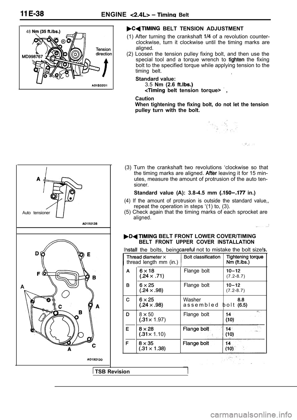
Auto tensioner
A
BELT TENSION ADJUSTMENT
(1) After turning the crankshaft
of a revolution counter-
clockwise, turn it clockwise until the timing marks are
aligned.
(2) Loosen the tension pulley fixing bolt, and then use the
special tool and a torque wrench to
the fixing
bolt to the specified torque while applying tension to the
timing belt.,
Standard value:
3.5 Nm (2.6
belt tension torque> ,
Caution
When tightening the fixing bolt, do not let the ten sion
pulley turn with the bolt.
(3) Turn the crankshaft two revolutions ‘clockwise so that
the timing marks are aligned.
leaving it for 15 min-
utes, measure the amount of protrusion of the auto ten-
sioner.
Standard value (A): 3.8-4.5 mm in.)
(4) If the amount of protrusion is outside the standard value,,
repeat the operation in steps ‘(1) to, (3).
(5) Check again that the timing marks of each sproc ket are
aligned.
BELT FRONT LOWER COVER/TIMING
BELT FRONT UPPER COVER INSTALLATION
II the bolts, being
thread length mm (in.)
850
1.97)
1.10)
not to mistake the bolt size!
Flange bolt
(7.2-8.7)
Flange bolt
(7.2-8.7)
Washer
a s s e m b l e d b o l t
Flange bolt
TSB Revision
Page 308 of 2103
ENGINE Timing Belt
TIMING BELT REMOVAL,,
Caution
If timing belt “B” is to be reused, use
it with an arrow on its flat side indicating the tu rning
direction (to the right).
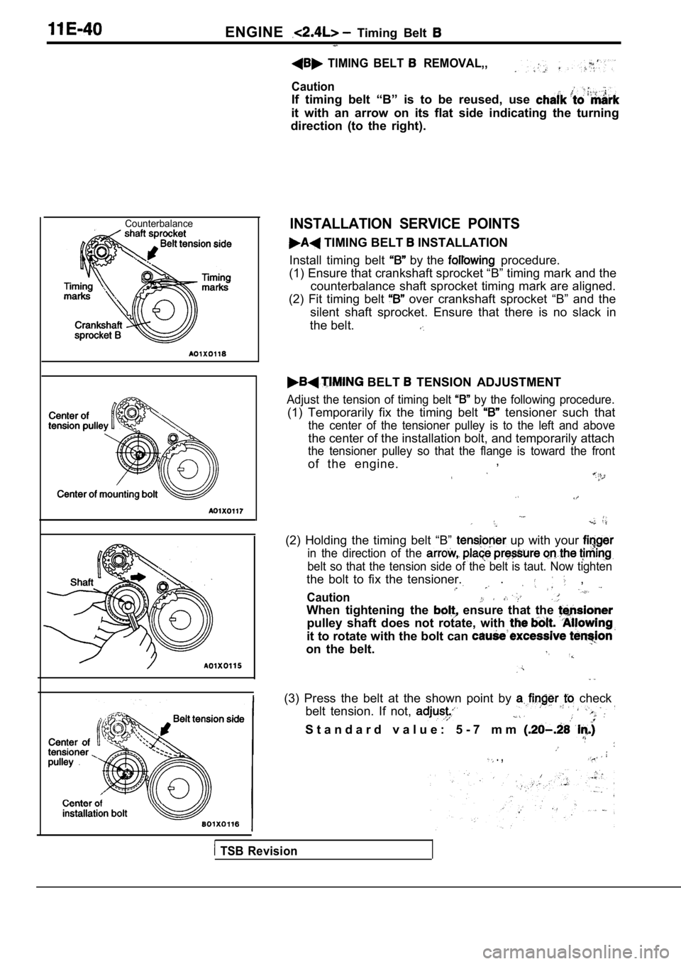
CounterbalanceINSTALLATION SERVICE POINTS
TIMING BELT INSTALLATION
Install timing belt
by the procedure.
(1) Ensure that crankshaft sprocket “B” timing mark and the
counterbalance shaft sprocket timing mark are align ed.
(2) Fit timing belt
over crankshaft sprocket “B” and the
silent shaft sprocket. Ensure that there is no slac k in
the belt.
BELT TENSION ADJUSTMENT
Adjust the tension of timing belt by the following procedure.
(1) Temporarily fix the timing belt tensioner such that
the center of the tensioner pulley is to the left a nd above
the center of the installation bolt, and temporarily attach
the tensioner pulley so that the flange is toward t he front
of the engine.,
(2) Holding the timing belt “B” up with your
in the direction of the
belt so that the tension side of the belt is taut.
Now tighten
the bolt to fix the tensioner.. ,
Caution
When tightening the ensure that the
pulley shaft does not rotate, with
it to rotate with the bolt can
on the belt.
(3) Press the belt at the shown point by check
belt tension. If not,
S t a n d a r d v a l u e : 5 - 7 m m
. ,
TSB Revision
Page 324 of 2103
ENGINE OVERHAUL Timing Belt , ,
REMOVAL SERVICE POINTS
TIMING BELT REMOVAL
Mark belt running direction for reinstallation.
NOTE
(1) Water or oil on the belt shorten its life drastically, so the
removed timing belt, sprocket, and tensioner must b e
free from oil and water. These parts should not be washed.
Replace parts if seriously contaminated.
(2) If there is oil or water on each part check fro nt case
oil seals, camshaft oil seal and water pump for lea ks.
OIL PUMP SPROCKET REMOVAL
CRANKSHAFT BOLT LOOSENING
CRANKSHAFT SPROCKET REMOVAL
BELT “B”
(1) Make a mark on the back of the timing belt indi cating
the direction of rotation so it may be reassembled in the
same direction if it is to be reused.
NOTE
(1) Water or oil on the belt shortens life drastically,
so the removed timing belt, sprocket, and tensioner must be free from oil and
should
not be washed. Replace parts if seriously contami-
nated.
TSBRevision
Page 325 of 2103
ENGINE OVERHAUL Timing Belt
(2) If there is oil or water on each part check front case
oil seals, camshaft oil seal and water pump leaks.’
COUNTERBALANCE SHAFT SPROCKET
REMOVAL
SPROCKET “B” REMOVAL
CAMSHAFT SPROCKET BOLT LOOSENING
INSTALLATION SERVICE POINTS
CAMSHAFT SPROCKET
TSB RevisionI
Page 327 of 2103
ENGINE OVERHAUL Timing Belt
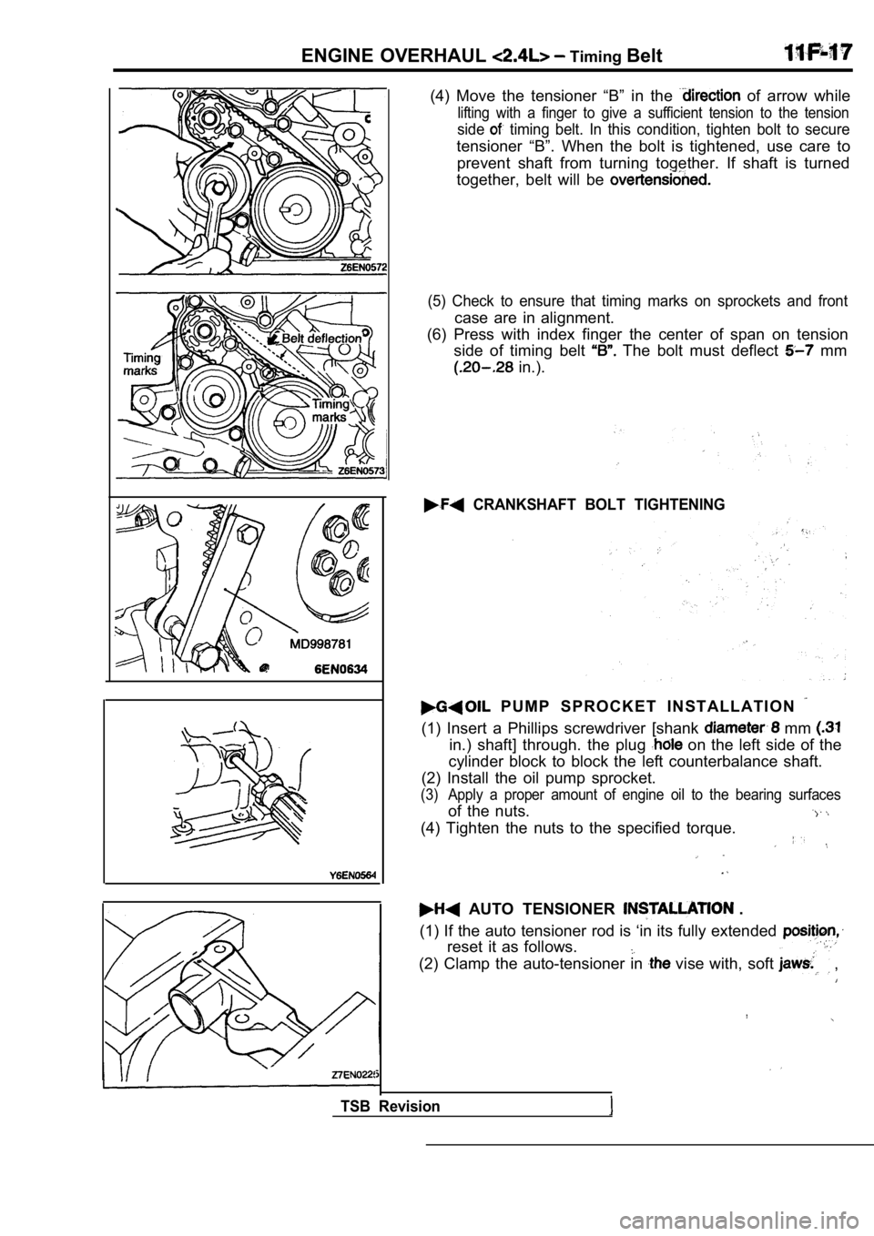
(4) Move the tensioner “B” in the of arrow while
lifting with a finger to give a sufficient tension to the tension
side timing belt. In this condition, tighten bolt to secure
tensioner “B”. When the bolt is tightened, use care to
prevent shaft from turning together. If shaft is tu rned
together, belt will be
(5) Check to ensure that timing marks on sprockets and front
case are in alignment.
(6) Press with index finger the center of span on t ension
side of timing belt
The bolt must deflect mm
in.).
CRANKSHAFT BOLT TIGHTENING
P U M P S P R O C K E T I N S T A L L A T I O N
(1) Insert a Phillips screwdriver [shank mm
in.) shaft] through. the plug on the left side of the
cylinder block to block the left counterbalance sha ft.
(2) Install the oil pump sprocket.
(3) Apply a proper amount of engine oil to the beari ng surfaces
of the nuts.
(4) Tighten the nuts to the specified torque.
AUTO TENSIONER .
(1) If the auto tensioner rod is ‘in its fully exte nded
reset it as follows.
(2) Clamp the auto-tensioner in vise with, soft ,
TSB Revision
Page 329 of 2103
ENGINE OVERHAUL Belt
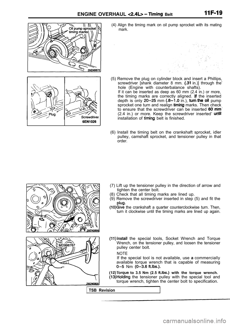
(4) Align the timing mark on oil pump sprocket with its mating
mark.
(5) Remove the plug on cylinder block and insert a Phillips,
screwdriver [shank diameter 8 mm. in.)] through the’
hole (Engine with counterbalance shafts).
If it can be inserted as deep as 60 mm (2.4 in.) or more,
the timing marks are correctly aligned. the inserted
depth is only
mm in.), pump
sprocket one turn and realign
marks. Then check
to ensure that the screwdriver can be inserted
(2.4 in.) or more. Keep the screwdriver inserted’
installation of belt is finished.
(6) Install the timing belt on the crankshaft sproc ket, idler
pulley, camshaft sprocket, and tensioner pulley in that
order.
(7) Lift up the tensioner pulley in the direction of arrow and
tighten the center bolt.
(8) Check that all timing marks are lined up. (9) Remove the screwdriver inserted in step (5) and fit the
the crankshaft a quarter counterclockwise turn. Then,
turn it clockwise until the timing marks are lined up again.
the special tools, Socket Wrench and Torque
Wrench, on the tensioner pulley, and loosen the ten sioner
pulley center bolt.
to 3.5 Nm (2.5 with the torque wrench.
the tensioner pulley with the special tool and
torque wrench, tighten the center bolt to specifica tion.
NOTE
If the special tool is not available, use acommercially
available torque wrench that is capable of measurin g
Nm
TSB Revision
Page 331 of 2103
ENGINE OVERHAUL Timing
Rounded edge
Abnormal wear (Fluffy strand)
in.)(1) Check the auto tensioner for possible leaks and replace
as necessary.
INSPECTION
TIMING BELT
Replace belt if any of the following exist.
(1) Hardening of back
Back side is glossy without resilience, and leaves no indent
when pressed fingernail.:’
(2) Cracks on rubber back.
(3) Cracks or peeling of canvas.
(4) Cracks on rib root.
(5) Cracks on belt sides.
(6) Abnormal wear of belt sides. The sides are norm al if
they are sharp as if cut by a knife.
(7) Abnormal wear on teeth.
(8) Missing tooth.
AUTO TENSIONER
(2) Check the rod endfor wear or damage and replace as
necessary.
(3) Measure the rod protrusion. If it is out of spe cification,
replace the auto tensioner.
Standard value: 12 mm
in.)
TSB Revision
Page 342 of 2103
ENGINE OVERHAUL Rocker Arms Camshaft
I
INSPECTION
CAMSHAFT.
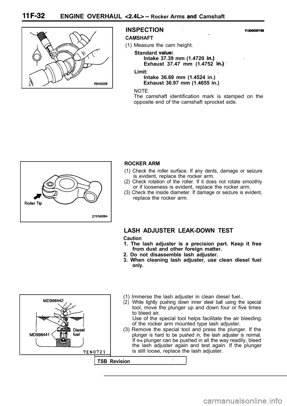
(1) Measure the cam height. Standard
Intake 37.39 mm (1.4720
Exhaust 37.47 mm (1.4752
Limit:
Intake 36.69 mm (1.4524 in.)
Exhaust 36.97 mm (1.4655 in.)
NOTE
The camshaft identification mark is stamped on the
opposite end of the camshaft sprocket side.
ROCKER ARM
(1) Check the roller surface. If any dents, damage or seizure
is evident, replace the rocker arm.
(2) Check rotation of the roller. If it does not rotate smoothly
or if looseness is evident, replace the rocker arm.
(3) Check the inside diameter. If damage or seizure is evident,
replace the rocker arm.
LASH ADJUSTER LEAK-DOWN TEST
Caution
1. The lash adjuster is a precision part. Keep it f ree
from dust and other foreign matter.
2. Do not disassemble lash adjuster.
3. When cleaning lash adjuster, use clean diesel fu el
only.
Use of the special tool helps facilitate the air bleeding.
of the rocker arm mounted type lash adjuster.
(3) Remove the special tool and press the plunger. If the
plunger is hard to be pushed in, the lash adjuster is normal.
Ifthe plunger can be pushed in all the way readily, bleed
the lash adjuster again and test again. If the plun ger
is still loose, replace the lash adjuster.
TSB Revision
(1) Immerse the lash adjuster in clean diesel fuel. .
(2)While lightly pushing down inner steel ball using t he special
tool, move the plunger up and down four or five tim es
to bleed air.