1990 MITSUBISHI SPYDER check engine
[x] Cancel search: check enginePage 394 of 2103
ENGINE (NON-TURBO)>
LEAK DETECTION PUMP MONITOR
Related diagnosis trouble codes (DTC)
l EVAP leak monitor small leak detected
l
EVAP leak monitor large leak detected
l
EVAP leak monitor pinched hose found
Operation
The leak detection assembly incorporates two primar y functions: it must detect a the
system and seal the evaporative system so the leak detection test can be run.. .
The’ primary components within the assembly are: A three port solenoid activates ‘both of the
functions listed above; a pump which contains a swi tch; two check valves and a spring/diaphragm, a’
canister vent valve (CVV) seal which contains a spr ing loaded vent seal valve.
Immediately after a cold start, between predetermin ed temperature thresholds limits, the three port
solenoid is briefly energized. This initializes the pump by drawing air into the pump cavity and also closes
the vent seal. During non test conditions the vent seal is held open by the pump diaphragm assembly
which pushes it open at the full travel position. The vent seal will remain closed while the pump is c ycling
due to the reed switch triggering of the three port solenoid that prevents the diaphragm assembly from
reaching full travel. After the brief initializatio n period, the solenoid is de-energized allowing atm ospheric
pressure to enter the pump cavity, thus permitting the spring to drive the diaphragm which forces air
out of the pump cavity and into the vent system. Wh en the solenoid is energized and de-energized,
the cycle is repeated creating flow in typical diaphragm pump fashion. The pump is controlled in 2 mod es:
Pump Mode: The pump is cycled at a fixed rate to achieve a rapid pressure build in order to shorten
the overall test length.
Test Mode: The solenoid is energized with a fixed d uration pulse. Subsequent fixed pulses occur
when the diaphragm reaches the Switch closure point .
The spring in the pump is set so that the system wi ll achieve an equalized pressure of about 7.5”
The cycle rate of pump strokes is quite rapid as the system begins to pump up to this pressure.
As the pressure
the cycle rate starts to drop off. If there is no leak in the system, the pump
would eventually stop pumping at the equalized pres sure. If there is a leak, it will continue to pump
at a rate representative of the flow characteristic of the size of the leak. From this information we can
determine if the leak is larger than the required d etection limit (currently set at
orifice by CARB).
If a leak is revealed during the leak test portion of the test, the test is terminated at the end of the
mode and no further system checks will be performed .
After passing the leak detection phase of the test, system pressure is maintained by turning on the
solenoid until the purge system is activated. Purg e activation in effect creates a leak. The cycle
rate is again interrogated and when it increases du e to the flow through the purge system, the leak
check portion of the diagnostic is complete.
The canister vent valve will unseal the system afte r completion of the test sequence as the pump
diaphragm assembly moves to the full travel positio n.
Evaporative system functionality will be verified b y using the stricter evap purge flow monitor. At an
appropriate warm idle the LDP will be energized to seal the canister vent. The purge flow will be clocked
up from some small value in an attempt to see a shi ft in the 02 control system. If fuel vapor, indicated
by a shift in the 02 control, is present the test i s passed. If not, it is assumed that the purge syst em
is not functioning in some respect. The LDP is agai n turned off and the test is ended.
TSB Revision
Page 395 of 2103
ENGINE (NON-TURBO)>
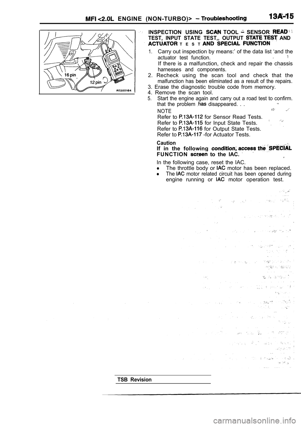
INSPECTION USING TOOL SENSOR
TEST, INPUT STATE TEST,, OUTPUT AND
T E S T
1.Carry out inspection by means:’ of the data list ‘and the
actuator test function.
If there is a malfunction, check and repair the cha ssis
harnesses and components.
2. Recheck using the scan tool and check that the
malfunction has been eliminated as a result of the repairs.
3. Erase the diagnostic trouble code from memory.
4. Remove the scan tool.
5.Start the engine again and carry out a road test to confirm.
that the problem
disappeared. . .
NOTE
Refer to for Sensor Read Tests.
Refer to
for Input State Tests.
Refer to
for Output State Tests.
Refer to -for Actuator Tests.
Caution
If in the following
F U N C T I O N to the IAC.
In the following case, reset the IAC.
lThe throttle body or motor has been replaced.
lThe motor related circuit has been opened during
engine running or motor operation test.
TSB Revision
Page 398 of 2103
ENGINE (NON-TURBO)> Troubleshooting
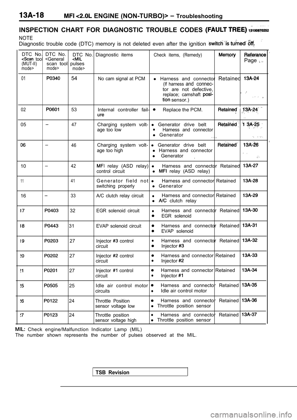
INSPECTION CHART FOR DIAGNOSTIC TROUBLE CODES
NOTE
Diagnostic trouble code (DTC) memory is not deleted even after the ignition
DTC No. DTC No.
DTC No. Diagnostic itemsCheck items, (Remedy) tool
mode>
mode>
01 54No cam signal at PCMl Harness and connector Retained
(If harness and connec-
tor are not defective,
replace; camshaft ,
sensor.) ,
02 53
Internal controller fail- Replace the PCM.,
. .
0547
46
Charging system volt- l Generator drive belt
age too lowlHarness and connector
l Generator. . ,
Charging system volt- l Generator drive belt
age too highl Harness and connector
l Generator
1042
1 141
1633
relay (ASD relay) lHarness and connector Retained
control circuitl relay (ASD relay)
G e n e r a t o r f i e l d n o t lHarness and connector Retained
switching properlyl Generator
A/C clutch relay circuitlHarness and connector Retained
l clutch relay
32
31
27
27
27
25
24
24
EGR solenoid circuitlHarness and connector Retained
EGR solenoid
EVAP solenoid circuit
Harness and connector Retained
EVAP solenoid
Injector
controllHarness and connector Retained
circuitInjector
Injector controlHarness and connector Retained
circuitlInjector
Injector controlHarness and connector Retained
circuitlInjector
Idle air control motor Harness and connector Retained
circuitslIdle air control motor
Throttle PositionHarness and connector Retained
sensor voltage lowl Throttle position sensor
Throttle positionlHarness and connector Retained
sensor voltage highl Throttle position sensor
TSB Revision
Check engine/Malfunction Indicator Lamp (MIL)
The number shown represents the number of pulses ob served at the MIL.
Page 399 of 2103
ENGINE (NON-TURBO)>
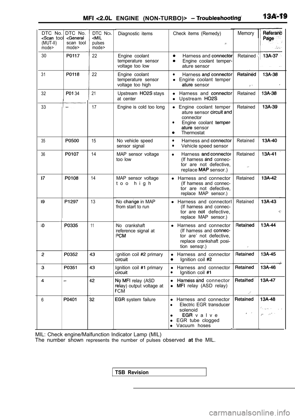
1MemoryDiagnostic itemsCheck items (Remedy)
Engine coolantHarness and
temperature sensorEngine coolant temper
voltage too low
ature sensor
Engine coolantlHarness
temperature sensorl Engirie coolant temper
voltage too high sensor
Upstream staysl Harness and
at centerl Upstream
Engine is cold too longl Engine coolant temper
ature sensor
connectorlEngine coolant
sensor
Thermostat
No vehicle speed
lHarness and
sensor signallVehicle speed sensor
MAP sensor voltagelHarness
too low (If harness connec-
tor are not defective, replace
sensor.)
MAP sensor voltagel Harness and connector
t o o h i g h
(If harness and connec-
tor are not defective,
replace MAP sensor.)
No
in MAPl Harness and connector
from start to run (If harness and connec-
tor are defective,
replace MAP sensor.)
No crankshaftl Harness and connector
reference signal at (If harness and
tor are’ not defective,
replace crankshaft posi-
tion sensqr.)
gnition coil
primaryl Harness and connector
Ignition coil
gnition coil primaryl Harness and connectorlIgnition coil
relay (ASDl connector
ay) output voltage atl relay (ASD relay)
‘CM
system failurel Harness and connector
lElectric EGR transducer
solenoid
l v a l v e
l EGR tube clogged
l Vacuum hoses
DTC NC
pulses
mode>
DTC No. DTC No. tool (MUT-II)scan toolmode>mode>
30
31
32 34
1
I
I
I
I
Retained22
22
,
I
I
I
Retained
Retained
21
17
15
14
14
33
35Retained
36Retained
Retained
13Retained
11
6
MIL: Check engine/Malfunction Indicator Lamp (MIL)
The number shown represents the number of pulses observedatthe MIL.
TSB Revision
Page 400 of 2103
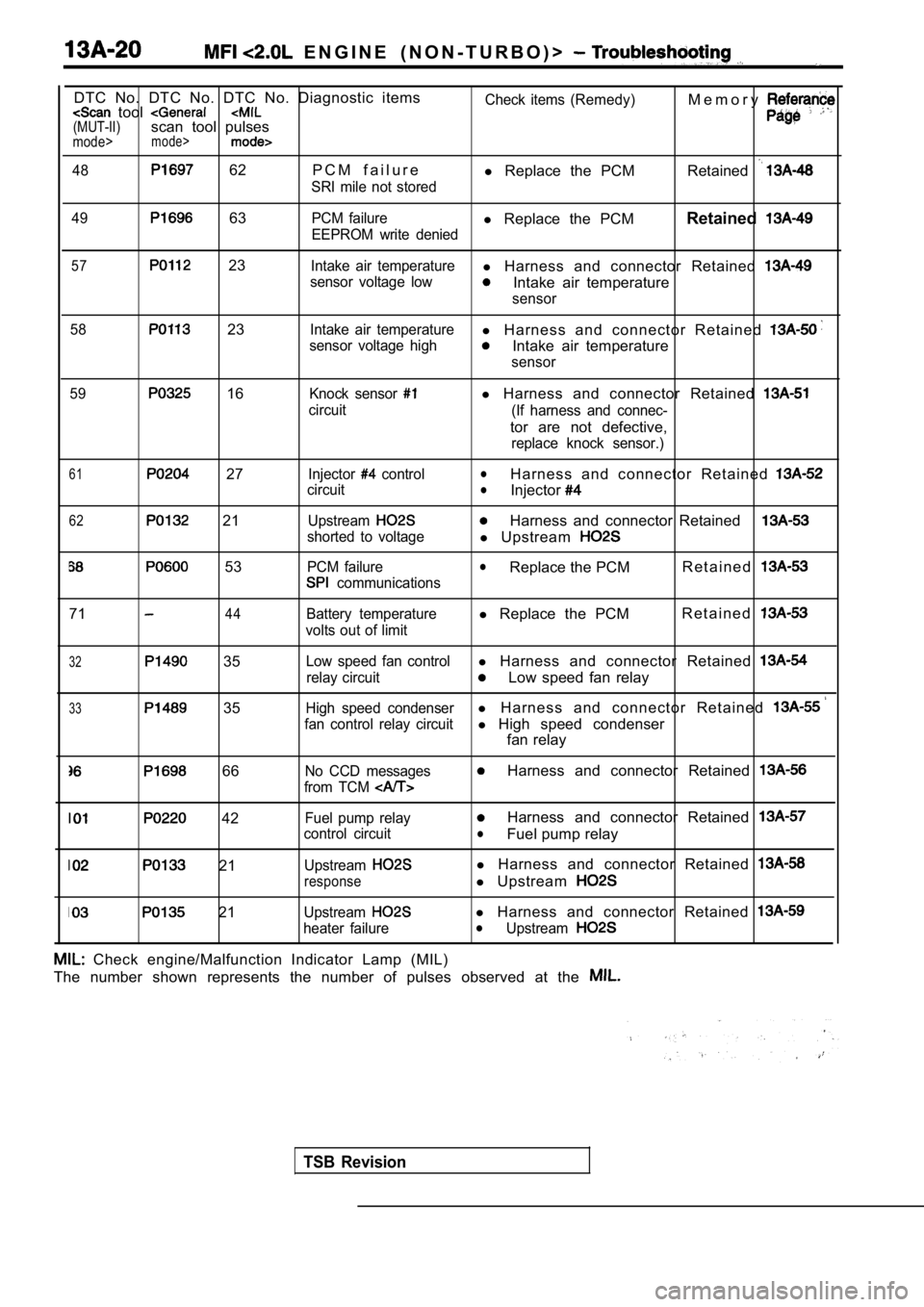
E N G I N E ( N O N - T U R B O ) >
DTC No. DTC No. DTC No. Diagnostic items tool (MUT-II)scan tool pulsesmode>mode>
48 62 P C M f a i l u r e
SRI mile not storedCheck items (Remedy)
l
Replace the PCM M e m o r yRetained
49 63PCM failurel
Replace the PCM Retained
EEPROM write denied
57 23Intake air temperaturel Harness and connector Retained
sensor voltage lowIntake air temperature
sensor
58
23Intake air temperaturel H a r n e s s a n d c o n n e c t o r R e t a i n e d
sensor voltage highIntake air temperature
sensor
59
16Knock sensor
circuit
l Harness and connector Retained
(If harness and connec-
tor are not defective,
replace knock sensor.)
61 27
62 21
53
Injector control
circuit
Upstream
shorted to voltage
PCM failure
communications
lH a r n e s s a n d c o n n e c t o r R e t a i n e d lInjector
Harness and connector Retained
l Upstream
lReplace the PCM R e t a i n e d
7144Battery temperature
volts out of limitl Replace the PCM R e t a i n e d
32 35
33 35
Low speed fan controll
Harness and connector Retained
relay circuitLow speed fan relay
High speed condenserl H a r n e s s a n d c o n n e c t o r R e t a i n e d
fan control relay circuitl High speed condenser
fan relay
66No CCD messages
from TCM Harness and connector Retained
42
21
21
Fuel pump relay
control circuit
Upstream
response
Upstream
heater failure
Harness and connector Retained
lFuel pump relay
l Harness and connector Retained
l Upstream
l Harness and connector Retained lUpstream
Check engine/Malfunction Indicator Lamp (MIL)
The number shown represents the number of pulses ob served at the
TSB Revision
Page 401 of 2103
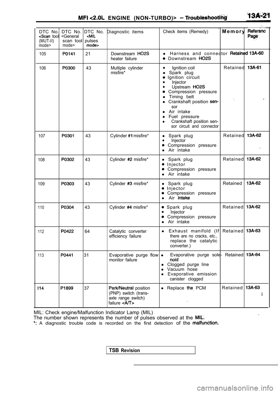
ENGINE (NON-TURBO)>
DTC No. DTC No. DTC No. Diagnostic items tool
105 21Downstream
heater failure
106 43Multiple cylinder
misfire* Check items (Remedy)
M e m o r y
l
H a r n e s s a n d c o n n e c t o r
D o w n s t r e a m
lIgnition coil R e t a i n e d
l
Spark plug
Ignition circuitlInjectorlUpstream
Compression pressure
l Timing belt
l Crankshaft position
sor
l Air intake
l Fuel pressure
lCrankshaft position sen-
sor circuit and connector
107
43 Cylinder misfire*
l Spark plug R e t a i n e dlInjector
Compression pressure
l Air intake
108 43Cylinder misfire*l Spark plug R e t a i n e d
I n j e c t o r
Compression pressure
l Air intake
109 43Cylinder misfire*l Spark plug Retained
I n j e c t o r
Compression pressure
l Air
110 43Cylinder misfire* Spark plug R e t a i n e dlInjector
Compression pressure
l Air intake
112 64Catalytic converter
efficiency failurel E x h a u s t m a n i f o l d ( I f R e t a i n e d
there are no cracks, etc.,
replace the catalytic
converter.)
113 31 Evaporative purge flow
lEvaporative purge sole- Retained
monitor failurel
Clogged purge line
l Vacuum hose
l Evaporative emission
canister clogged
37 position
(PNP) switch (trans-
axle range switch)
failurel Replace PCMR e t a i n e d
.&
MIL: Check engine/Malfunction Indicator Lamp (MIL)
.
The number shown represents the number of pulses ob served at the
A diagnostic trouble code is recorded on the first detection of the
TSBRevision
Page 402 of 2103
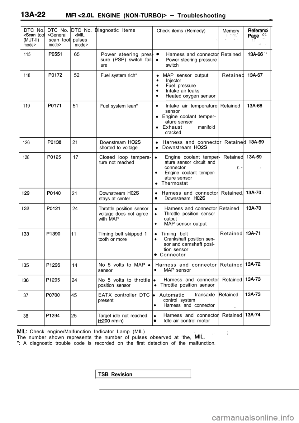
ENGINE (NON-TURBO)> Troubleshooting
DTC No. DTC No. DTC No. Diagnostic i t e m s
Check items (Remedy) Memory tool
115 65 Power steering pres- Harness and connector Retained
sure (PSP) switch fail-
lPower steering pressure
ureswitch
118 52Fuel system rich*l MAP sensor output R e t a i n e dlInjectorlFuel pressurelIntake air leakslHeated oxygen sensor
119 51Fuel system lean*lIntake air temperature Retained
sensor
l Engine coolant temper-
ature sensor
l E x h a u s t
manifold
cracked
126 21
128 17
Downstreaml H a r n e s s a n d c o n n e c t o r R e t a i n e d
shorted to voltagel Downstream
Closed loop tempera- lEngine coolant temper- Retained
ture not reached ature sensor circuit and
connector
lEngine coolant temper-
ature sensor
l Thermostat
21
24
11
Downstreaml Harness and connector Retained,
stays at centerDownstream
Throttle position sensorlHarness and connector Retained
voltage does not agreelThrottle position sensor
with MAP output
lMAP sensor output
Timing belt skipped 1 l
Timing belt R e t a i n e d
tooth or morelCrankshaft position sen-
sor and camshaft posi-
tion sensor
C o n n e c t o r
37
14
24
45 No 5 volts to MAP
l H a r n e s s a n d c o n n e c t o r R e t a i n e d
sensorlMAP sensor
No 5 volts to throttle lHarness and connector Retained
position sensorl
Throttle position sensor
EATX controller DTC l A u t o m a t i c transaxle Retained
present
control systemlHarness and connector
38 25Target idle not reachedlHarness and connector Retained
Idle air control motor
Check engine/Malfunction Indicator Lamp (MIL)
The number shown represents the number of pulses ob served at ‘the,
A diagnostic trouble code is recorded on the first detection of the malfunction.
TSB Revision
Page 403 of 2103
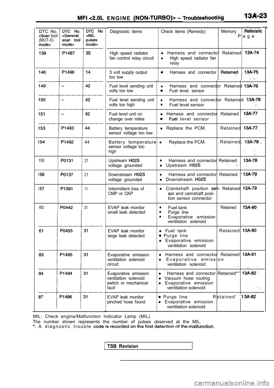
E N G I N E
DTC No. tool(MUT-II)
155
44
21
21
11
6031
Diagnostic items Check items (Remedy) Memory
P a g e
High speed radiatorl Harness and connector Retained’
fan control relay circuitlHigh speed radiator fan
relay
5 volt supply outputHarness and connector
too low
Fuel level sending unitlHarness and connector Retained
volts too lowFuel level. sensor
Fuel level sending unit
lHarness and connector Retained
volts too highlFuel level sensor
Fuel level unit nol Harness and connector Retained
change over miles l e v e l s e n s o r
Battery temperaturel Replace the PCM. R e t a i n e d
sensor voltage too low
B a t t e r y t e m p e r a t u r e lReplace the PCM. R e t a i n e d , ,
sensor voltage too
high
UpstreamlHarness and connector Retained
voltage groundedl
Upstream
DownstreamlHarness and connector’ Retained
voltage groundedl Downstream
Intermittent loss of
CMP or CKPl Crankshaft position Retained
and camshaft posi-
tion sensor connector
EVAP leak monitor
small leak detectedlFuel tank ‘RetainedlPurge linelEvaporative emissionventilation solenoid
EVAP leak monitor
large leak detected
l Fuel tank R e t a i n e d
P u r g e l i n e
l Evaporative emission
ventilation solenoid
Evaporative emission
ventilation solenoid
circuit
Evaporative emission
ventilation solenoid
switch or mechanical
fault
l Harness and connector Retained
l E v a p o r a t i v e e m i s s i o n
ventilation solenoid
l Harness and connector Retained*“’
l Vacuum hose routing
l Evaporative emission
ventilation solenoid
EVAP leak monitor
pinched hose found P u r g e l i n e R e t a i n e d ’
l
Evaporative emission
ventilation solenoid
MIL: Check engine/Malfunction Indicator Lamp (MIL)
The number shown represents the number of pulses ob served at the MIL.
A d i a g n o s t i c t r o u b l e
TSB Revision