1990 MITSUBISHI SPYDER transmission
[x] Cancel search: transmissionPage 36 of 2103
Lubrication and
GENERAL Lubricants and Lubricant Capacities Table
Use of fuels containing alcohol is not recommended
unless the nature of the blend can be determined
as being satisfactory.
Gasohol
A mixture of 10% ethanol (grain alcohol)
and 90% unleaded gasoline may be used in your
car.
If problems are experienced as a result
of using gasohol, it is recommended that the car
be operated on gasoline.
Methanol Do not use gasolines containing
methanol (wood alcohol). Use of this type of alcohol
can result in vehicle performance deterioration and
damage critical parts in the fuel system compo-
nents. Fuel system damage and performance prob-
lems, resulting from the use of gasolines containin g
methanol, may not be covered by the new car war-
ranty.
Gasolines containing
Ether)
Unleaded gasoline containing 15% or
may be used in car. Fuel containing MTBE
over 15% vol. may cause reduced engine perfor-
mance and produce vapor lock or hard starting.
MATERIALS
TO FUEL
Indiscriminate use of fuel system -cleaning’
should be avoided. Many of these materials in-
tended for gum and varnish removal
highly active solvents or similar ingredients that
can be harmful to gasket and diaphragm materials
used in fuel system component
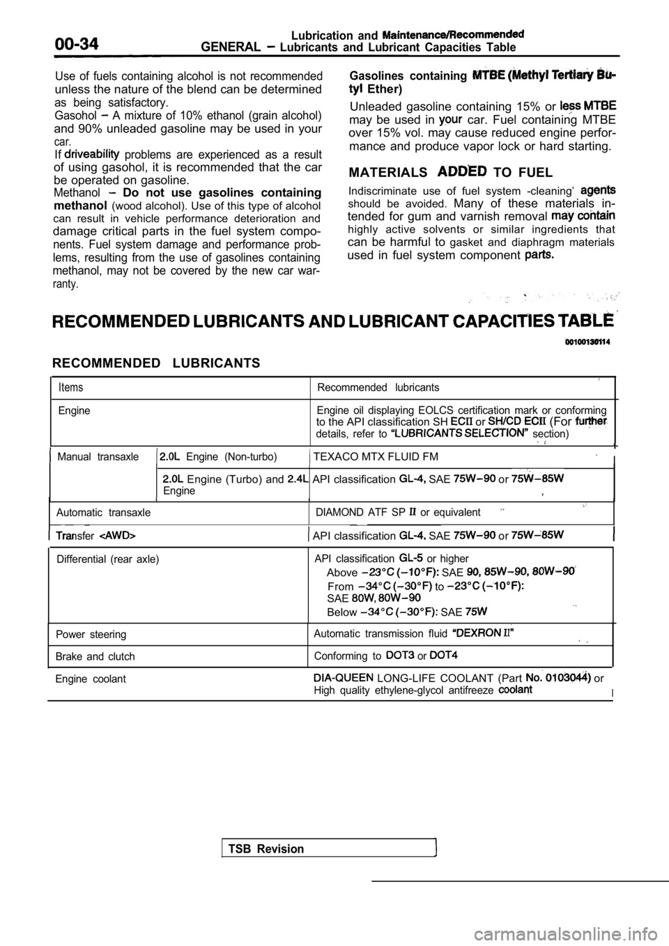
RECOMMENDED LUBRICANTS
Items
Engine
Recommended lubricants
Engine oil displaying EOLCS certification mark or c onforming
to the API classification SH or (For
details, refer to section)
Manual transaxle Engine (Non-turbo) TEXACO MTX FLUID FM I
Engine (Turbo) and API classification SAE or
Engine,
Automatic transaxle DIAMOND ATF SP or equivalent
TSB Revision
Transfer API classification SAE or
Differential (rear axle)API classification or higher
Above SAE
From to
SAE
Below SAE
Power steering
Brake and clutch Automatic transmission fluid
Conforming to or
Engine coolant LONG-LIFE COOLANT (Part or
High quality ethylene-glycol antifreeze I
Page 49 of 2103
GENERALMaintenance Service
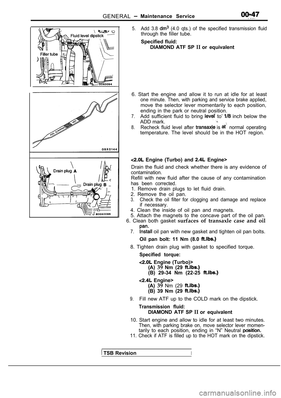
5.Add 3.8 (4.0 qts.) of the specified transmission fluid
through the filler tube.
Specified fluid:DIAMOND ATF SP IIor equivalent
6. Start the engine and allow it to run at idle for at least
one minute. Then, with parking and service brake ap plied,
move the selector lever momentarily to each positio n,
ending in the park or neutral position.
7.Add sufficient fluid to bring to’ inch below the
ADD mark.
8.Recheck fluid level after is normal operating
temperature. The level should be in the HOT region.
Engine (Turbo) and Engine>
Drain the fluid and check whether there is any evid ence of
contamination.
Refill with new fluid after the cause of any contam ination
has been corrected.
1. Remove drain plugs to let fluid drain.
2. Remove the oil pan.
3.Check the oil filter for clogging and damage and re place
if necessary.
4. Clean the inside of oil pan and magnets.
5. Attach the magnets to the concave part of the oi l pan.
6. Clean both gasket surfaces of transaxle case and oil
7. oil pan with new gasket and tighten oil pan bolts.
Oil pan bolt: 11 Nm (8.0
8. Tighten drain plug with gasket to specified torq ue.
Specified torque:
Engine (Turbo)>
(A) 39Nm (29
(B) 29-34 Nm (22-25
Engine>
(A) 39Nm (29
(B) 39 Nm (29
9.Fill new ATF up to the COLD mark on the dipstick.
Transmission fluid:
DIAMOND ATF SP IIor equivalent
10. Start engine and allow to idle for at least two minutes.
Then, with parking brake on, move selector lever mo men-
tarily to each position, ending in “N” Neutral
11. Check if ATF is filled up to the HOT mark on the dipstick.
TSB RevisionI
Page 528 of 2103
ENGINE (TURBO)
AND
ENGINE> Troubleshooting
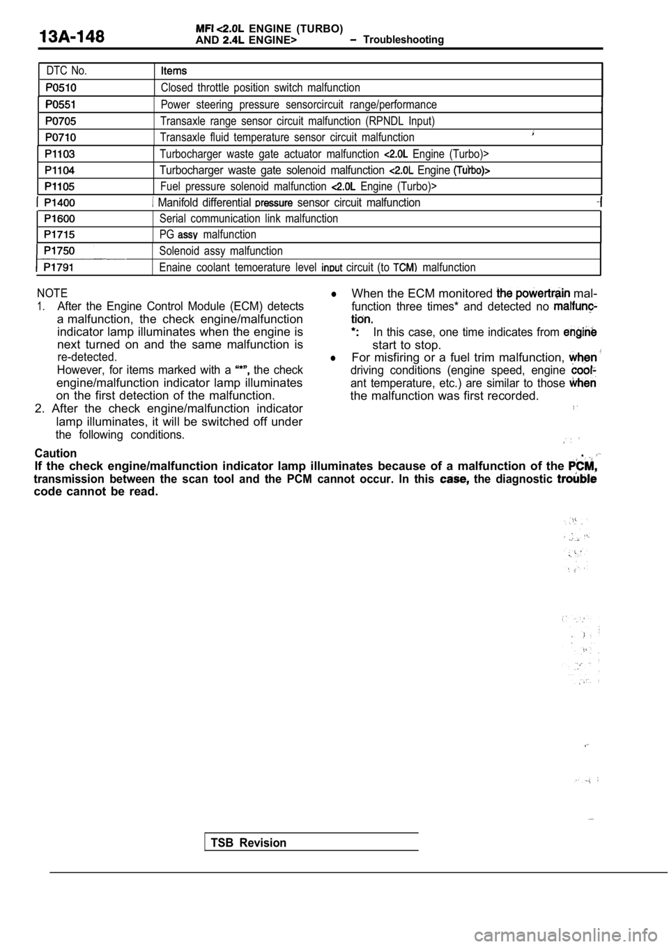
DTC No.
Closed throttle position switch malfunction
Power steering pressure sensorcircuit range/perfor mance
Transaxle range sensor circuit malfunction (RPNDL Input)
Transaxle fluid temperature sensor circuit malfunct ion
Turbocharger waste gate actuator malfunction Engine (Turbo)>
Turbocharger waste gate solenoid malfunction Engine
Fuel pressure solenoid malfunction Engine (Turbo)>
Manifold differential sensor circuit malfunction
Serial communication link malfunction
PG
malfunction
Solenoid assy malfunction
Enaine coolant temoerature level
circuit (to malfunction
NOTElWhen the ECM monitored mal-
1.After the Engine Control Module (ECM) detects function three times* and detected no
a malfunction, the check engine/malfunction
indicator lamp illuminates when the engine isIn this case, one time indicates from
next turned on and the same malfunction is
start to stop.
re-detected.lFor misfiring or a fuel trim malfunction,
However, for items marked with a the checkdriving conditions (engine speed, engine
engine/malfunction indicator lamp illuminatesant temperature, etc.) are similar to those
on the first detection of the malfunction. the malfunction was first recorded.
2. After the check engine/malfunction indicator
lamp illuminates, it will be switched off under
the following conditions.
Caution,
If the check engine/malfunction indicator lamp illu minates because of a malfunction of the
transmission between the scan tool and the PCM cann ot occur. In this the diagnostic
code cannot be read.
TSB Revision
Page 535 of 2103
ENGINE (TURBO)
AND
ENGINE> Troubleshooting .
6. Other monitoring
lMisfire
l Evaporative emission control system
l Idle air control system
l Manifold differential pressure sensor
lExcessive time to enter closed loop fuel control
l Throttle position sensor
l Barometric pressure sensor
Intake air temperature sensor
l Serial communication link
l Crankshaft position sensor
l Camshaft position sensor
Volume air flow sensor
Test conditions/procedure
l Engine coolant temperature sensor
l Closed throttle position switch
l Generator terminal circuit
l sensor circuit
l sensor heater circuit
Turbocharger waste gate solenoid
l EGR solenoid
lEvaporative emission purge solenoid
l Evaporativeemissionventilation
solenoid Engine>
l Fuel pressure solenoid
lInjector circuit
1. All of the following conditions should be satisf ied when the drive test is carried out.
(1) Engine coolant temperature:
or higher (when engine is fully warmed up)
(2) Outside air temperature:
or higher
(3)
condition:
lSelector lever position: range
l Overdrive switch: ON
lPower/economy changeover switch: Power
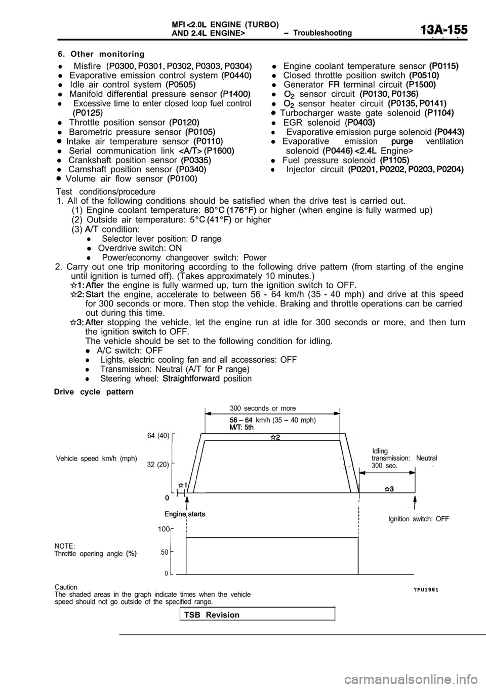
2. Carry out one trip monitoring according to the f ollowing drive pattern (from starting of the engine
until ignition is turned off). (Takes approximately 10 minutes.)
the engine is fully warmed up, turn the ignition s witch to OFF.
the engine, accelerate to between 56 64 km/h (35 40 mph) and drive at this speed
for 300 seconds or more. Then stop the vehicle. Bra king and throttle operations can be carried
out during this time.
stopping the vehicle, let the engine run at idle f or 300 seconds or more, and then turn
the ignition
to OFF.
The vehicle should be set to the following conditio n for idling.
l A/C switch: OFF
lLights, electric cooling fan and all accessories: O FF
lTransmission: Neutral (A/T for range)
lSteering wheel: position
Drive cycle pattern
300 seconds or more
km/h (35 40 mph)
64 (40)
Idling
Vehicle speed km/h (mph) transmission: Neutral
32 (20)
300 seo.
,
Ignition switch: OFF
100
NOTE:Throttle opening angle 50
0
Caution
The shaded areas in the graph indicate times when t he vehicle
speed should not go outside of the specified range.
TSB Revision
Page 571 of 2103
![MITSUBISHI SPYDER 1990 Service Repair Manual ENGINE (TURBO)
AND ENGINE> Troubleshooting
Code No. Power Steering Pressure Sensor CircuitProbable cause
[Comment] Power pressure switch Backgroundl Open or shorted power steering MITSUBISHI SPYDER 1990 Service Repair Manual ENGINE (TURBO)
AND ENGINE> Troubleshooting
Code No. Power Steering Pressure Sensor CircuitProbable cause
[Comment] Power pressure switch Backgroundl Open or shorted power steering](/manual-img/19/57345/w960_57345-570.png)
ENGINE (TURBO)
AND ENGINE> Troubleshooting
Code No. Power Steering Pressure Sensor CircuitProbable cause
[Comment] Power pressure switch Backgroundl Open or shorted power steering pressurelWhen the steering wheel is kept in the position during driving, the power
s w i t c h or steering pressure switch will be momentarily turned off. E n g i n e c o n t r o l f a i l e d ’lThe enginecontrol module checks whetherthe powerste ering pressure switch momentarilyturns off during driving.
Check Area Engine coolant temperature is or higher.
l Driving and stopping ‘2 are repeated times or more.“1: Engine speed is 2,500 or higher, volumetric efficiency is 55% or higher, and this
condition continues for 2 seconds or more.
l 2: Engine speed is 600 or lower.
Judgement Criterial Power steering pressure switch stays on without cha nging.
NGCheck the power steering press On-vehicle Service) Replace
lDisconnect the connector and measure at the harness side.
NG
between ECM and power pressure switch
NG
the ECM. Replace the ECM.
Code No. Transmission Range Sensor Circuit
Malfunction (RPNDL Input)
[Comment]
Background
lWhen a malfunction of the park/neutral position swi tch is detected, the transaxle control
module outputs amalfunction signal to the engine control module.
Check Area, Judgement Criteria l
control module.
Check the TCM. (Refer to GROUP Troubleshooting.)
Repair
Repair
cause
l Park/neutral position switch failedlOpen or shorted park/neutral position switchcircuit, or loose connector.
l Engine control module failed.
Code No. Turbocharger Waste Gate Actuator
Malfunction
(Turbo)> Probable cause
l
Turbocharger waste gateactuator failed.
l Charging pressure control system failed.
l Engine control module failed.[Comment]
Background
lThe engine control module checks that the engine is not overcharged by always monitoringintake air volume.lThe engine control module protects the engine by shutting off fuel when an overcharged
condition is detected.
Check Area
Engine coolant temperature is higher than
Judgement Criterial Volumetric efficiency has continued to be not lower than 200% for 1.5 sec.
Check the turbocharger supercharging. (Refer to GROUP 15
On-vehicle Service.)
TSB Revision
Page 923 of 2103
MANUAL OVERHAUL
Transaxle
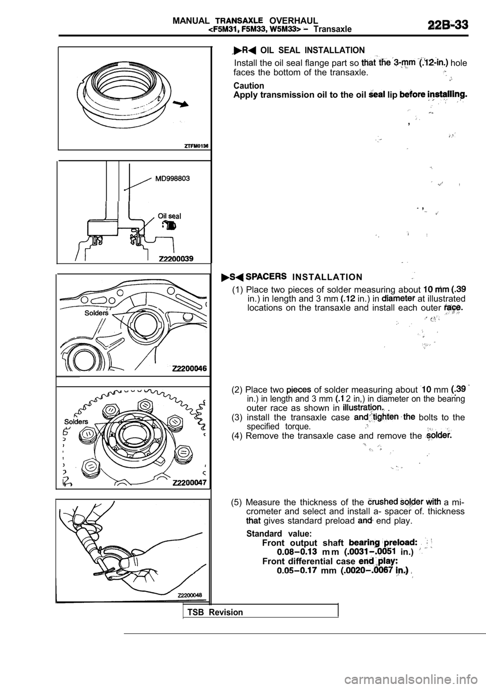
Oil seal
OIL SEAL INSTALLATION
Install the oil seal flange part so hole
faces the bottom of the transaxle.
Caution
Apply transmission oil to the oil lip
,
,
,
I N S T A L L A T I O N
(1) Place two pieces of solder measuring about
in.) in length and 3 mm in.) in at illustrated
locations on the transaxle and install each outer
(2) Place two of solder measuring about mm
in.) in length and 3 mm 2 in,) in diameter on the beanng
outer race as shown in .
(3) install the transaxle case
bolts to the
specified torque.
(4) Remove the transaxle case and remove the
(5) Measure the thickness of the a mi-
crometer and select and install a- spacer of. thick ness
gives standard preload end play.
Standard value:
Front output shaft
m m in.)
Front differential case
mm
TSB Revision
Page 965 of 2103
MANUAL TRANSAXLE OVERHAUL,.
Case“ , ,
I , ,
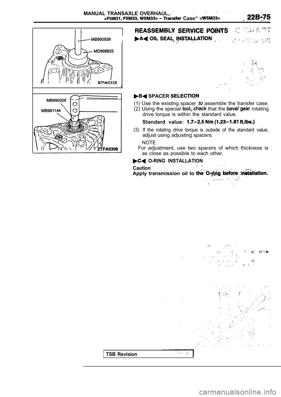
SPACER
(1) Use the existing spacer assemble the transfer case.
(2) Using the special
that the rotating
drive torque is within the standard value.
Standard value:
(3) If the rotating drive torque is outside of the stan dard value,
adjust using adjusting spacers.
NOTE
For adjustment, use two spacers of which thickness is
as close as possible to each other.
O-RING INSTALLATION .Caution
Apply transmission oil to
. . . ..
TSB Revision
Page 1020 of 2103
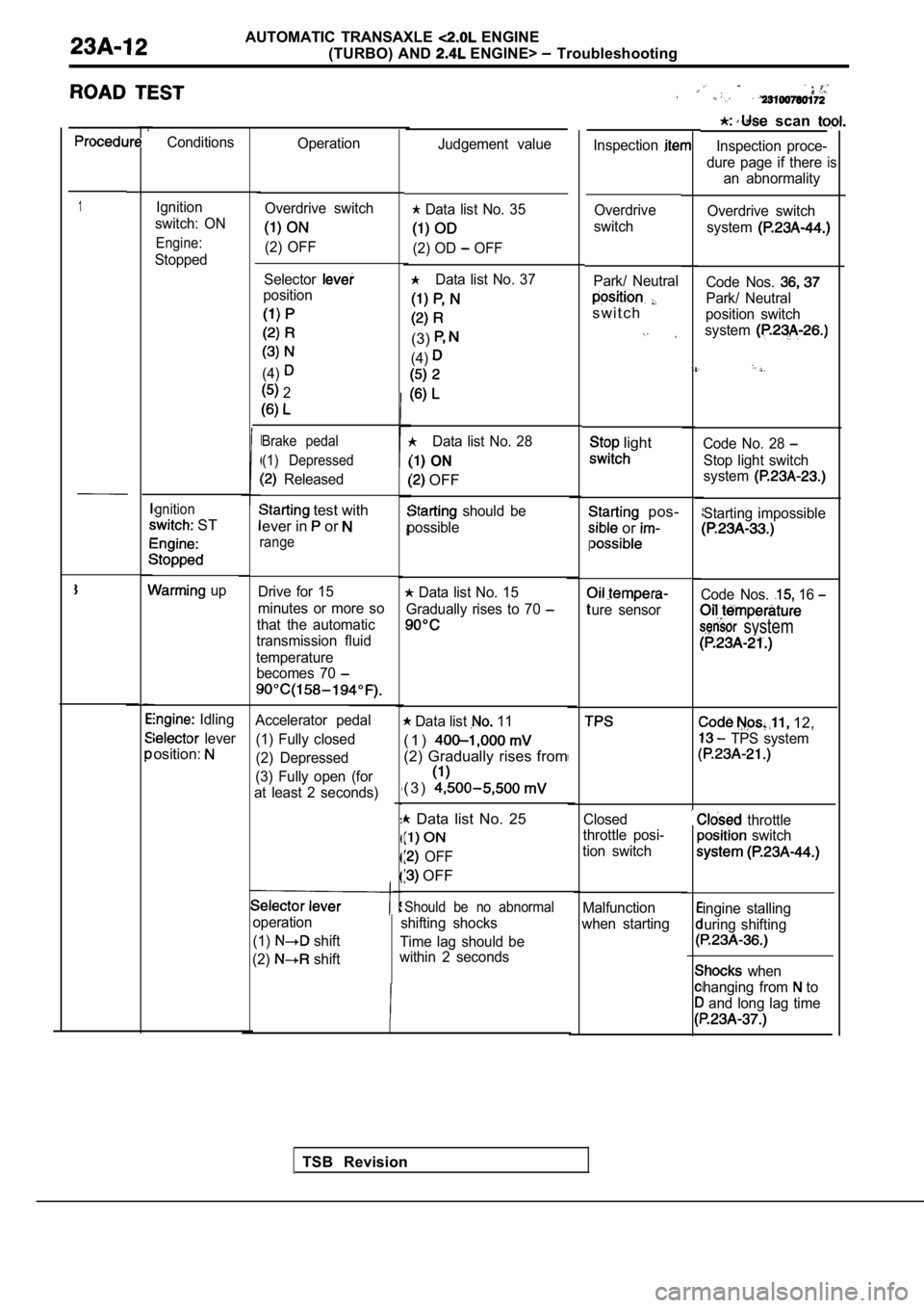
AUTOMATIC TRANSAXLE ENGINE
(TURBO) AND
ENGINE> Troubleshooting
scan
Inspection proce-
dure page if there an abnormality
is
Conditions Operation
Inspection
1Ignition
switch: ON
Engine:
Stopped
gnition
ST
up
Idling
lever
osition:
Judgement value
Overdrive switch
system
Code Nos.
Park/ Neutral
position switch
system
Code No. 28
Stop light switch
system
Starting impossible
Code Nos. 16
system
12,
TPS system
throttle switch
ingine stalling
uring shifting
when
hanging from
to
and long lag time
Overdrive switch
(2) OFF
Data list No. 35
(2) OD OFF
Data list No. 37
(3)
(4)
Data list No. 28
ON
OFF
should be
possible Overdrive
switch
Selector
position
(4)
2
Park/ Neutral
s w i t c h
Brake pedal (1) Depressed
Released
light
pos-
or
I
ure sensor
test with
ever in
or
range
Drive for 15
minutes or more so
that the automatic
transmission fluid
temperature becomes 70 Data list No. 15
Gradually rises to 70
Accelerator pedal
(1) Fully closed
(2) Depressed
(3) Fully open (for
at least 2 seconds) Data list 11
( 1 )
(2) Gradually rises from
( 3 )
Data list No. 25
OFF
OFF
Closed
throttle posi-
tion switch
Should be no abnormal
shifting shocks
Time lag should be
within 2 seconds Malfunction
when starting
operation
(1)
shift
(2)
shift
TSB Revision