1990 MITSUBISHI SPYDER cooling
[x] Cancel search: coolingPage 37 of 2103
GENERAL Recommended Lubricants and Lubricant Table
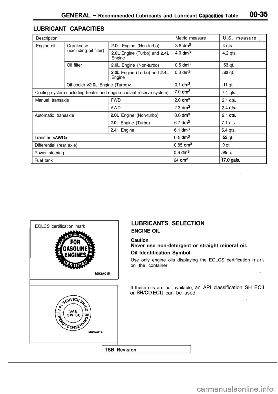
LUBRICANT CAPACITIES
DescriptionMetric measureU . S . m e a s u r e
Engine oil Crankcase Engine (Non-turbo)3.8
(excluding oil filter) 4 qts. Engine (Turbo) and 4.0
Engine4.2 qts.
Oil filter
Engine (Non-turbo) 0.5 qt.
Engine (Turbo) and 0.3
Engine
qt.
Oil cooler
Engine (Turbo)> 0.1 qt.
Cooling system (including heater and engine coolant reserve system)7.07.4 qts.
Manual transaxleFWD2.02.1 qts.
AWD2.32.4
Automatic transaxle Engine (Non-turbo)8.69.1
Engine (Turbo)
6.77.1 qts.
2.41 Engine 6.16.4 qts.
Transfer
0.5 qt.
Differential (rear axle) 0.85
qt.
Power steering
0.9 q t .
Fuel tank 64
EOLCS certification markLUBRICANTS SELECTION
ENGINE OIL
Caution
Never use non-detergent or straight mineral oil.
Oil Identification Symbol
Use only engine oils displaying the EOLCS certifica tion mark
on the container.
If these oils are not available, an API classification SH ECII
or
can be used.
TSB Revision
Page 38 of 2103
GENERAL Recommended Lubricants and Capacities
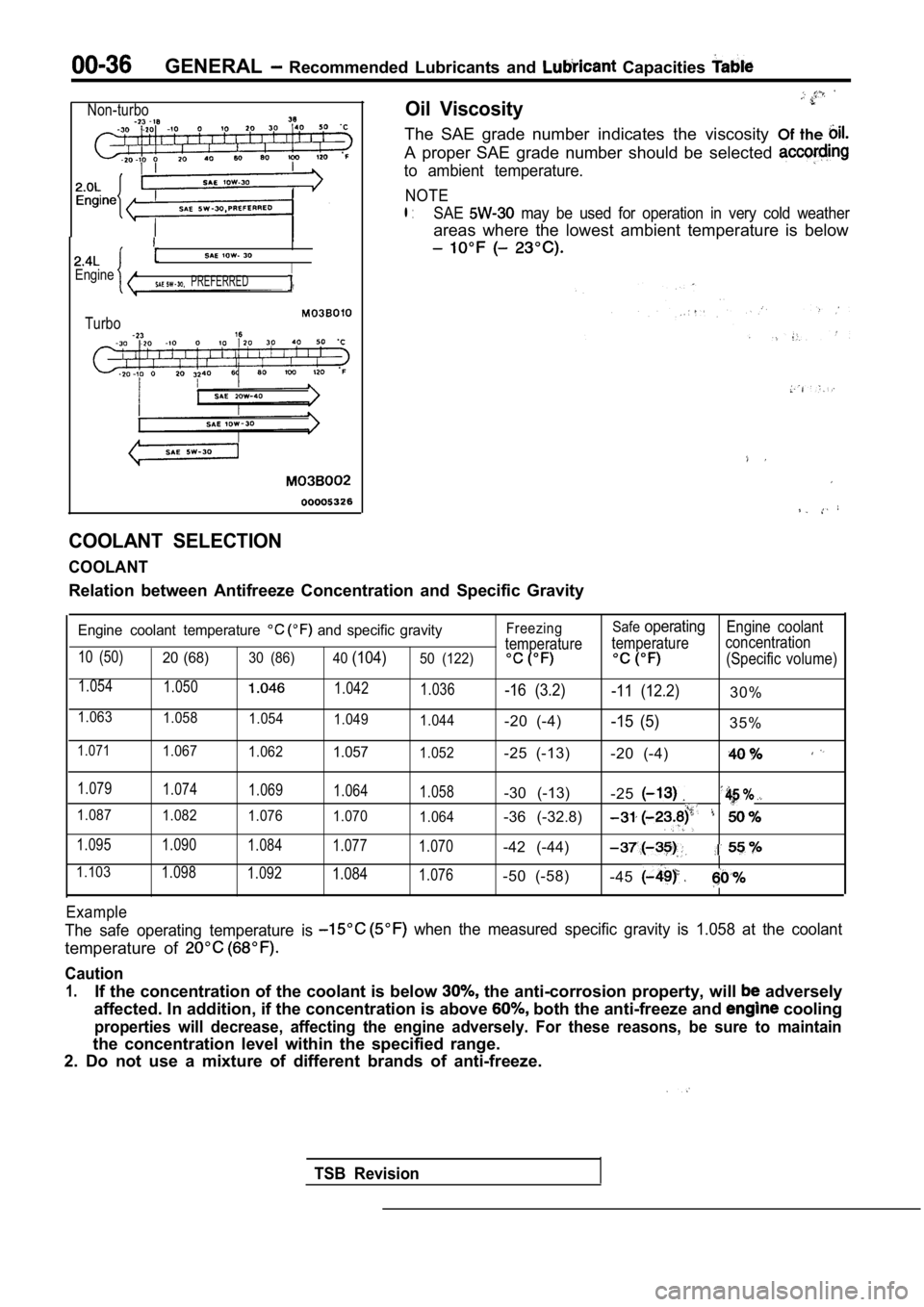
Non-turbo
I
EngineI PREFERRED
Turbo
Oil Viscosity
The SAE grade number indicates the viscosity Of the
A proper SAE grade number should be selected
to ambient temperature.
NOTE
l :SAE may be used for operation in very cold weather
areas where the lowest ambient temperature is below
COOLANT SELECTION
COOLANT
Relation between Antifreeze Concentration and Speci fic Gravity
Engine coolant temperature and specific gravity
10 (50)20 (68)30 (86)
40(104)50 (122)
1.054
1.0501.042
1.036
1.0631.058 1.0541.049
1.044
1.0711.0671.0621.0571.052 Freezing
Safe
operatingEngine coolant
temperature temperature concentration
(Specific volume)
-16 (3.2)
-11 (12.2)30%
-20 (-4)
-15 (5)35%
-25 (-13) -20 (-4)
1.079
1.074 1.0691.064
1.058-30 (-13)-25
1.0871.082 1.0761.070
1.064-36 (-32.8)
1.095 1.090 1.0841.077
1.070-42 (-44)
1.1031.0981.0921.0841.076-50 (-58)-45
Example
The safe operating temperature is when the measured specific gravity is 1.058 at the coolant
temperature of
Caution
1.If the concentration of the coolant is below the anti-corrosion property, will adversely
affected. In addition, if the concentration is abov e
both the anti-freeze and cooling
properties will decrease, affecting the engine adve rsely. For these reasons, be sure to maintain
the concentration level within the specified range.
2. Do not use a mixture of different brands of anti -freeze.
TSB Revision
Page 50 of 2103
GENERAL Maintenance Service
,
Revision
Drain Plug
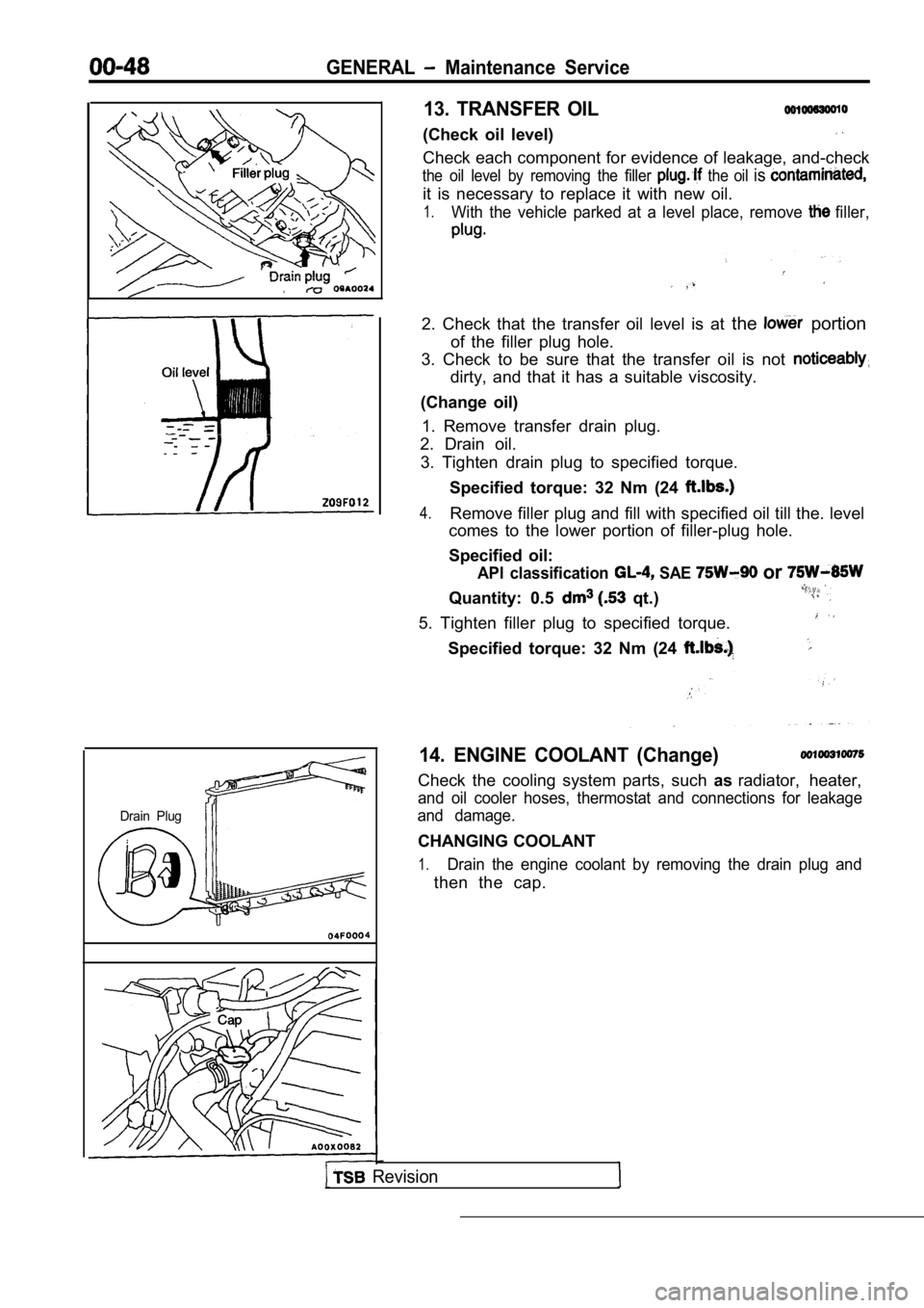
13. TRANSFER OIL
(Check oil level)
Check each component for evidence of leakage, and-check
the oil level by removing the filler the oil is
it is necessary to replace it with new oil.
1.With the vehicle parked at a level place, remove filler,
2. Check that the transfer oil level is at the portion
of the filler plug hole.
3. Check to be sure that the transfer oil is not
dirty, and that it has a suitable viscosity.
(Change oil) 1. Remove transfer drain plug.
2. Drain oil.
3. Tighten drain plug to specified torque.
Specified torque: 32 Nm (24
4.Remove filler plug and fill with specified oil till the. level
comes to the lower portion of filler-plug hole.
Specified oil:
API classification SAE or
Quantity: 0.5 qt.)
5. Tighten filler plug to specified torque.
Specified torque: 32 Nm (24
14. ENGINE COOLANT (Change)
Check the cooling system parts, such asradiator, heater,
and oil cooler hoses, thermostat and connections fo r leakage
and damage.
CHANGING COOLANT
1.Drain the engine coolant by removing the drain plug and
then the cap.
Page 69 of 2103
ENGINE On-vehicle
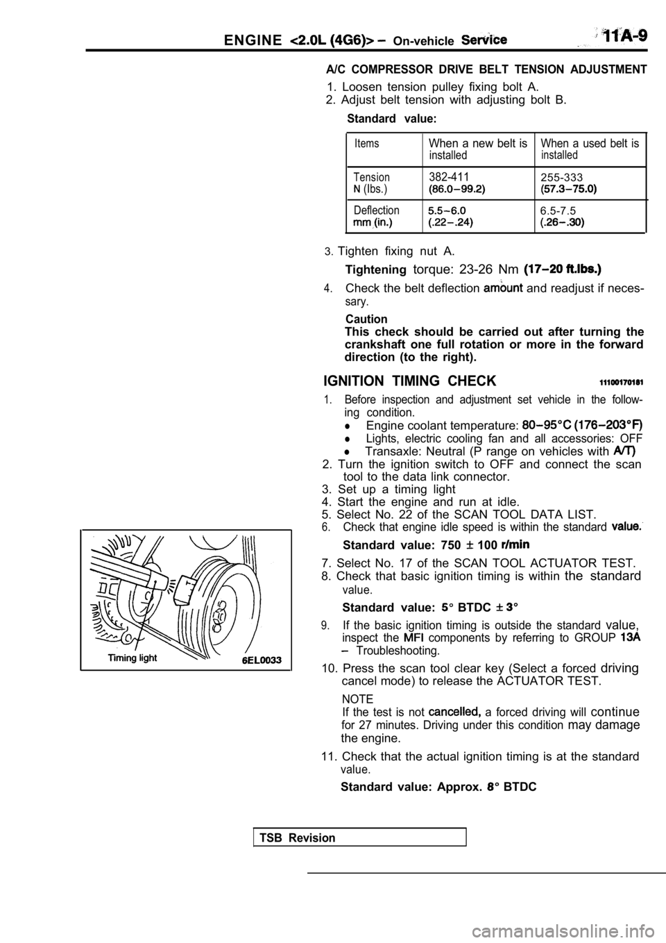
A/C COMPRESSOR DRIVE BELT TENSION ADJUSTMENT
1. Loosen tension pulley fixing bolt A.
2. Adjust belt tension with adjusting bolt B.
Standard value:
Items
Tension
(Ibs.)
Deflection
When a new belt isWhen a used belt is
installedinstalled
382-411255-333
6.5-7.5
3. Tighten fixing nut A.
Tightening torque: 23-26 Nm
4.Check the belt deflection and readjust if neces-
sary.
Caution
This check should be carried out after turning the
crankshaft one full rotation or more in the forward
direction (to the right).
IGNITION TIMING CHECK
1.Before inspection and adjustment set vehicle in the follow-
ing condition.
lEngine coolant temperature:
lLights, electric cooling fan and all accessories: OFF
lTransaxle: Neutral (P range on vehicles with
2. Turn the ignition switch to OFF and connect the scan
tool to the data link connector.
3. Set up a timing light
4. Start the engine and run at idle.
5. Select No. 22 of the SCAN TOOL DATA LIST.
6.Check that engine idle speed is within the standard
Standard value: 750 100
7. Select No. 17 of the SCAN TOOL ACTUATOR TEST.
8. Check that basic ignition timing is within the standard
value.
Standard value: BTDC
9.If the basic ignition timing is outside the standar d value,
inspect the components by referring to GROUP
Troubleshooting.
10. Press the scan tool clear key (Select a forced driving
cancel mode) to release the ACTUATOR TEST.
NOTE
If the test is not
a forced driving will continue
for 27 minutes. Driving under this condition may damage
the engine.
11. Check that the actual ignition timing is at the standard
value.
Standard value: Approx. BTDC
TSB Revision
Page 70 of 2103
ENGINE On-vehicle Service
NOTE
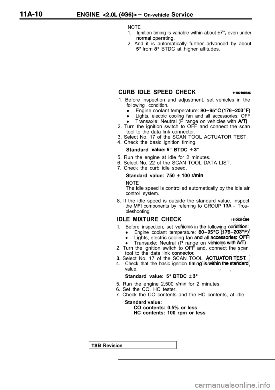
1.Ignition timing is variable within about even under
operating.
2. And it is automatically further advanced by abou t
from BTDC at higher altitudes.
CURB IDLE SPEED CHECK
1. Before inspection and adjustment, set vehicles in the
following condition.
lEngine coolant temperature:
lLights, electric cooling fan and all accessories: OFF
lTransaxle: Neutral (P range on vehicles with
2. Turn the ignition switch to OFF and connect the scan
tool to the data link connector.
3. Select No. 17 of the SCAN TOOL ACTUATOR TEST.
4. Check the basic ignition timing.
Standard
BTDC
5. Run the engine at idle for 2 minutes.
6. Select No. 22 of the SCAN TOOL DATA LIST.
7. Check the curb idle speed.
Standard value: 750
100
NOTE
The idle speed is controlled automatically by the i dle air
control system.
8. If the idle speed is outside the standard value, inspect
the components by referring to GROUP Trou-
bleshooting.
IDLE MIXTURE CHECK .
1.Before inspection, set in following
lEngine coolant temperature:
lLights, electric cooling fan all
lTransaxle: Neutral (P range on
2. Turn the ignition switch to OFF and, connect the scan
tool to the data link ,
3. Select No. 17 of the SCAN TOOL
4.Check that the basic ignition
value.
Standard value: BTDC
5. Run the engine 2,500 for 2 minutes.
6. Set the CO, HC tester.
7. Check the CO contents and the HC contents, at id le.
Standard value: CO contents: 0.5% or less
HC contents: 100 rpm or less
Revision
Page 71 of 2103

ENGINE On-vehicle
8. If the standard value is exceeded, check the following
items:
l Diagnostic output
l Closed-loop control (When the closed-loop control
is carried out normally, the output signal of the h eated
oxygen sensor repeats between and
,000 at idle.)
l Fuel pressure
I n j e c t o r
lIgnition coil, spark plug cable, spark plug
lEGR system and the EGR valve leak
l Evaporative emission control system
Compression pressure
NOTE
Replace the catalyst whenever the
HC contents do not remain inside the standard value .
(even though the result of the inspection is
all items.).
C O M P R E S S I O N
CHECK
1.Before inspection, check that the engine-oil, start er
battery are normal. Also, set the to the
condition:
lEngine coolant temperature:
lLights, electric cooling fan and all accessories: O FF
lTransaxle: Neutral (P range on vehicles with
2. Disconnect the spark plug cables.
3. Remove all of the spark plugs.
4.
5.
Disconnect the crankshaft position sensor connector .
NOTE
Doing this will prevent the engine control unit fro m carrying
out ignition and fuel injection.
Cover the spark plug hole with a shop towel etc., a nd
after the engine has been cranked, check that no fo reign
material is adhering to the shop towel.
TSB Revision
Page 73 of 2103
ENGINE On-vehicle Service
MANIFOLD VACUUM CHECK11100270200
1.Before inspection, set vehicles in the following condition:
lEngine coolant temperature:
lLights, electric cooling fan, and accessories: OFF
l Transaxle: Neutral (P range on vehicles with
2. Set up the tachometer or connect the scan tool t o the
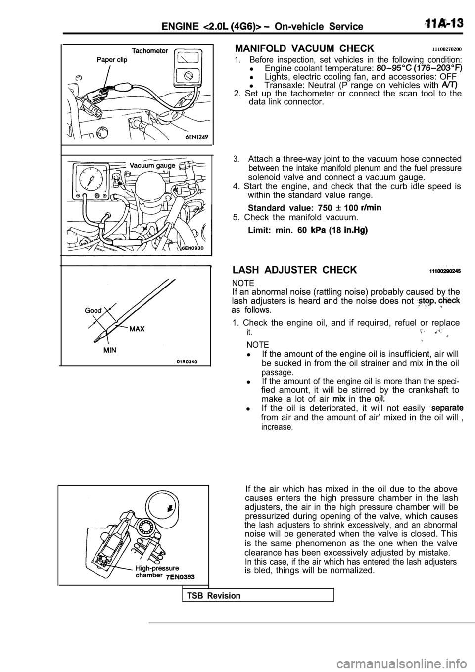
data link connector.
3.Attach a three-way joint to the vacuum hose connect ed
between the intake manifold plenum and the fuel pressure
solenoid valve and connect a vacuum gauge.
4. Start the engine, and check that the curb idle s peed is
within the standard value range.
Standard value: 750
100
5. Check the manifold vacuum.
Limit: min. 60
(18
LASH ADJUSTER CHECK
NOTE
NOTE
If an abnormal noise (rattling noise) probably caus ed by the
If an abnormal noise (rattling noise) probably caus ed by the
lash adjusters is heard and the noise does not
lash adjusters is heard and the noise does not
as follows.
as follows.
1. Check the engine oil, and if required, refuel or replace
it.
NOTE
lIf the amount of the engine oil is insufficient, ai r will
be sucked in from the oil strainer and mix
the oil
passage.
lIf the amount of the engine oil is more than the sp eci-
fied amount, it will be stirred by the crankshaft to
make a lot of air
in the
l If the oil is deteriorated, it will not easily
from air and the amount of air’ mixed in the oil wi ll ,
increase.
If the air which has mixed in the oil due to the ab ove
causes enters the high pressure chamber in the lash
adjusters, the air in the high pressure chamber wil l be
pressurized during opening of the valve, which caus es
the lash adjusters to shrink excessively, and an abnormal
noise will be generated when the valve is closed. T his
is the same phenomenon as the one when the valve
clearance has been excessively adjusted by mistake.
In this case, if the air which has entered the lash adjusters
is bled, things will be normalized.
TSB Revision
Page 106 of 2103
ENGINE OVERHAUL General Information
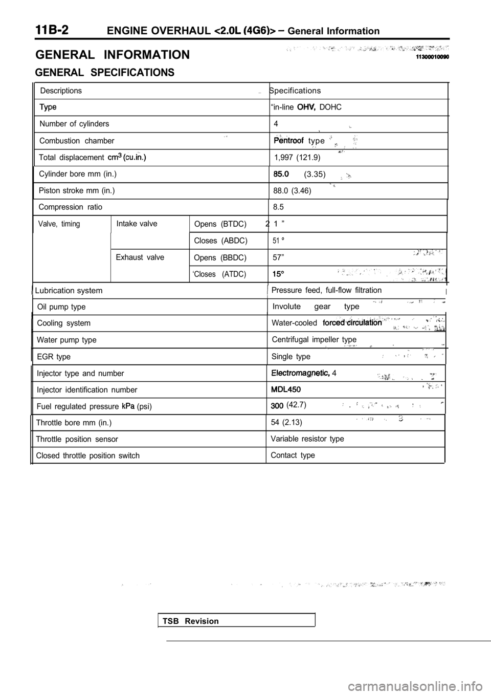
GENERAL INFORMATION
GENERAL SPECIFICATIONS
Descriptions
Number of cylinders
Combustion chamber
Total displacement
. . .Specifications
“in-line DOHC
4
type
1,997 (121.9)
Cylinder bore mm (in.)
Piston stroke mm (in.)
(3.35)
88.0 (3.46)
Compression ratio 8.5
Valve, timingIntake valve
Opens (BTDC)2 1 ”
Exhaust valve Closes (ABDC)
51
Opens (BBDC)
57”
‘Closes (ATDC)
Lubrication system Pressure feed, full-flow filtrationI
Oil pump type
Cooling system
Water pump type EGR type
I
Involute gear type
Water-cooled . .
Centrifugal impeller type
Single type,
TSB Revision
Injector type and number
Injector identification number
Fuel regulated pressure
(psi)
4
,
(42.7) .
Throttle bore mm (in.)
Throttle position sensor Closed throttle position switch 54 (2.13)
Variable resistor type
Contact type