1990 MITSUBISHI SPYDER compression ratio
[x] Cancel search: compression ratioPage 62 of 2103

ENGINE General Information
GENERAL INFORMATION
Items SpecificationsI
Number of cylinders
Bore mm (in.)
Stroke mm (in.)
In-line DOHC
85.0
(3.28)
Piston displacement
Compression ratio
Firing order
Counterbalance shaft8.5
Equipped
Valve timing Intake valve
Exhaust valve Opens
Closes
Opens
Closes 21 “BTDC
.
Lubrication systemIPressure feed-full flow , ,I
Oil pump type
LUBRICATION SYSTEM
Involute gear type
To
Camshaft
Counterbalance
TSB Revision
Oil
Oil pressure switch
Crankshaft
Counterbalance shaft
Page 66 of 2103
ENGINE,
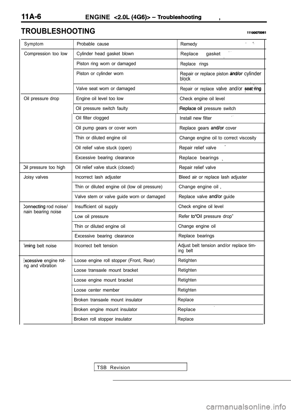
TROUBLESHOOTING
Oil filter cloggedInstall new filter
Oil pump gears or cover wornReplace gears cover
Thin or diluted engine oil Change engine oil to correct viscosity
Oil relief valve stuck (open) Repair relief valve
Excessive bearing clearanceReplace bearings
pressure too high Oil relief valve stuck (closed) Repair relief valve
Joisy valves Incorrect lash adjuster Bleed air or rep lace lash adjuster
Thin or diluted engine oil (low oil pressure)
Change engine oil ,
Valve stem or valve guide worn or damaged Replace va lve guide
rod noise/Insufficient oil supplyCheck engine oil level
nain bearing noise Low oil pressure Refer
pressure drop”
Thin or diluted engine oil Change engine oil
Excessive bearing clearance Replace bearings
belt noiseIncorrect belt tension Adjust belt tension and/or replace tim-ing belt
engine Loose engine roll stopper (Front, Rear)Retighten
ng and vibration
Loose transaxle mount bracketRetighten
Loose engine mount bracketRetighten
Loose center memberRetighten
Broken transaxle mount insulatorReplace
Broken engine mount insulatorReplace
Broken roll stopper insulatorReplace
Symptom
Probable cause
Remedy.
Compression too low Cylinder head gasket blownReplace gasket
Piston ring worn or damagedReplace rings
Piston or cylinder worn
Repair or replace piston cylinder
block
Valve seat worn or damagedRepair or replace valve and/or
Oil pressure drop Engine oil level too low Check engine oil level
Oil pressure switch faulty
pressure switch
TSB Revision
Page 72 of 2103
ENGINE On-vehicle
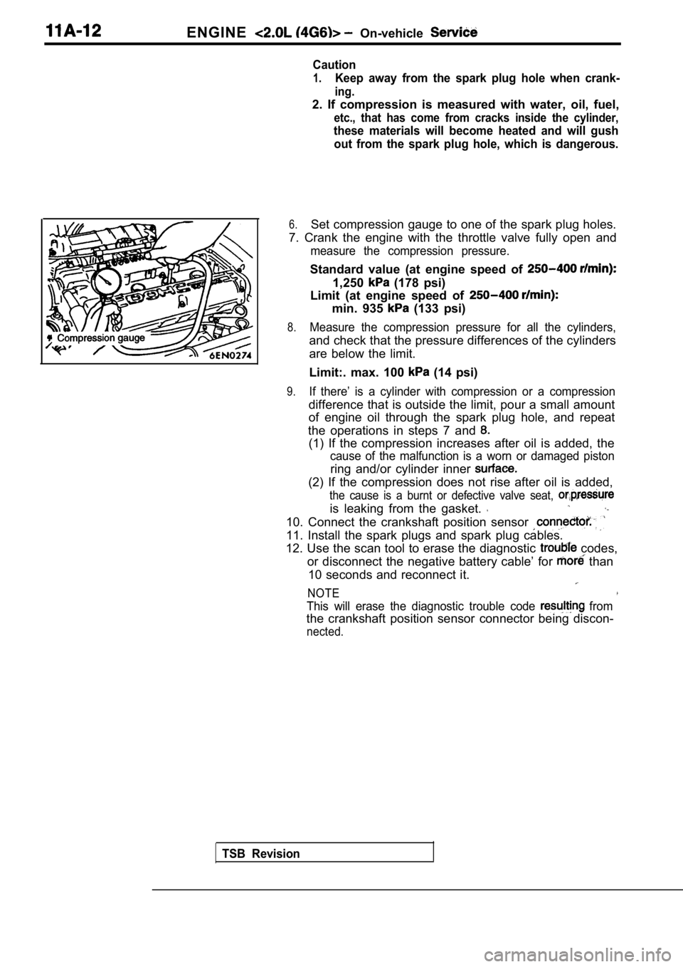
Caution
1.Keep away from the spark plug hole when crank-
ing.
2. If compression is measured with water, oil, fuel,
etc., that has come from cracks inside the cylinder ,
these materials will become heated and will gush
out from the spark plug hole, which is dangerous.
6.Set compression gauge to one of the spark plug hole s.
7. Crank the engine with the throttle valve fully o pen and
measure the compression pressure.
Standard value (at engine speed of
1,250 (178 psi)
Limit (at engine speed of
min. 935 (133 psi)
8.Measure the compression pressure for all the cylind ers,
and check that the pressure differences of the cylinders
are below the limit.
Limit:. max. 100
(14 psi)
9.If there’ is a cylinder with compression or a compr ession
difference that is outside the limit, pour a small amount
of engine oil through the spark plug hole, and repe at
the operations in steps 7 and
(1) If the compression increases after oil is added , the
cause of the malfunction is a worn or damaged pisto n
ring and/or cylinder inner
(2) If the compression does not rise after oil is added,
the cause is a burnt or defective valve seat,
is leaking from the gasket.
10. Connect the crankshaft position sensor
11. Install the spark plugs and spark plug cables.
12. Use the scan tool to erase the diagnostic
codes,
or disconnect the negative battery cable’ for
than
10 seconds and reconnect it.
NOTE
This will erase the diagnostic trouble code from
the crankshaft position sensor connector being disc on-
nected.
TSB Revision
Page 74 of 2103
ENGINE On-vehicle Service
Timing belt side
.
2.Start the engine and perform gentle racing* several times
(less than times.)
If the abnormal noise stops by racing, the air is b led
from the high pressure chamber of the lash adjusters
and the function of the lash adjusters is normalized.
After raising the engine speed from idling to 3000
gradually (in 30 seconds), drop the
ally (in 30 seconds) to idling.
NOTE
lIf the vehicle is parked on a slope for the oil
in the lash adjusters will be decreased ‘andairmay
enter the high pressure chamber when the
is started.
lAfter the vehicle is parked for long, air may enter
the high pressure chamber because the, oil in the
oil passage will be gone and, it will take a time b efore
the oil is supplied to the lash adjusters.
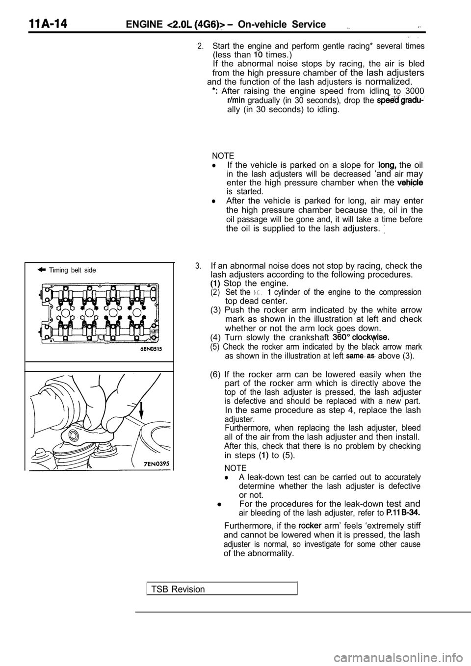
3.If an abnormal noise does not stop by racing, check the
lash adjusters according to the following procedure s.
Stop the engine.
(2)Set the NG. cylinder of the engine to the compression
top dead center.
(3) Push the rocker arm indicated by the white arro w
mark as shown in the illustration at left and check
whether or not the arm lock goes down.
(4) Turn slowly the crankshaft
(5) Check the rocker arm indicated by the black arr ow mark
as shown in the illustration at left above (3).
(6) If the rocker arm can be lowered easily when th e
part of the rocker arm which is directly above the
top of the lash adjuster is pressed, the lash adjus ter
is defective and should be replaced with a new part .
In the same procedure as step 4, replace the lash
adjuster.
Furthermore, when replacing the lash adjuster, bleed
all of the air from the lash adjuster and then install.
After this, check that there is no problem by check ing
in steps to (5).
NOTE
lA leak-down test can be carried out to accurately
determine whether the lash adjuster is defective
or not.
l For the procedures for the leak-down test and
air bleeding of the lash adjuster, refer to
Furthermore, if the arm’ feels ‘extremely stiff
and cannot be lowered when it is pressed, the lash
adjuster is normal, so investigate for some other c ause
of the abnormality.
TSB Revision
Page 85 of 2103
ENGINECamshaft and Oil Seal
CAMSHAFT CAP
C A M S H A F T
BEARING CAP
INSTALLATION
Tighten the bearing cap installation bolts to the torque
in two or three steps.
C a u t i o n
Tighten uniformly, otherwise the rocker arms not
straight.
Camshaft position
Camshaft positionsensor paint
CAMSHAFT OIL SEAL INSTALLATION
Use the special tool to drive the camshaft oil seal into position
carefully.
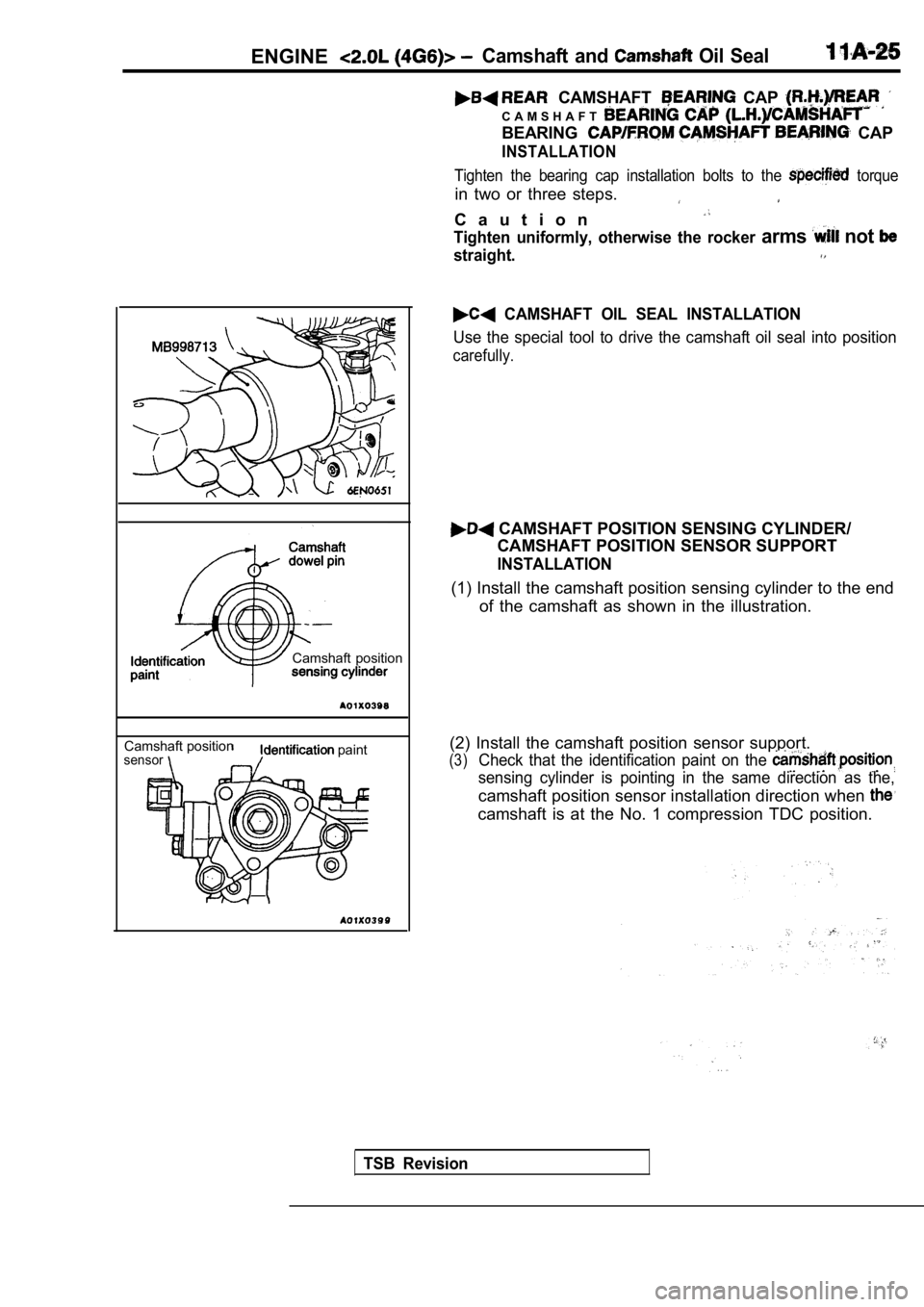
CAMSHAFT POSITION SENSING CYLINDER/
CAMSHAFT POSITION SENSOR SUPPORT
INSTALLATION
(1) Install the camshaft position sensing cylinder to the end
of the camshaft as shown in the illustration.
(2) Install the camshaft position sensor support.
(3)Check that the identification paint on the
sensing cylinder is pointing in the same direction as the,
camshaft position sensor installation direction when
camshaft is at the No. 1 compression TDC position.
TSB Revision
Page 106 of 2103
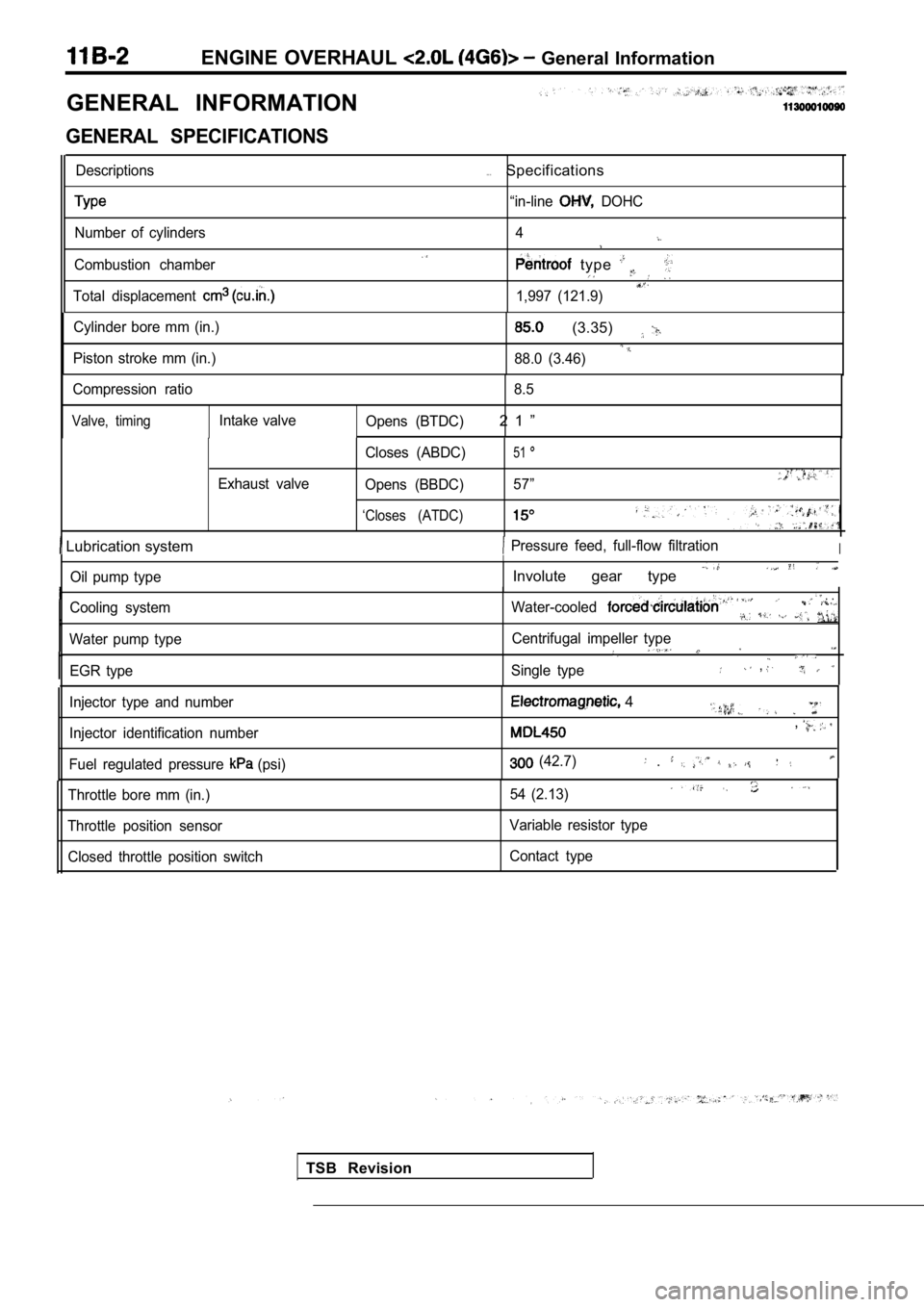
ENGINE OVERHAUL General Information
GENERAL INFORMATION
GENERAL SPECIFICATIONS
Descriptions
Number of cylinders
Combustion chamber
Total displacement
. . .Specifications
“in-line DOHC
4
type
1,997 (121.9)
Cylinder bore mm (in.)
Piston stroke mm (in.)
(3.35)
88.0 (3.46)
Compression ratio 8.5
Valve, timingIntake valve
Opens (BTDC)2 1 ”
Exhaust valve Closes (ABDC)
51
Opens (BBDC)
57”
‘Closes (ATDC)
Lubrication system Pressure feed, full-flow filtrationI
Oil pump type
Cooling system
Water pump type EGR type
I
Involute gear type
Water-cooled . .
Centrifugal impeller type
Single type,
TSB Revision
Injector type and number
Injector identification number
Fuel regulated pressure
(psi)
4
,
(42.7) .
Throttle bore mm (in.)
Throttle position sensor Closed throttle position switch 54 (2.13)
Variable resistor type
Contact type
Page 172 of 2103
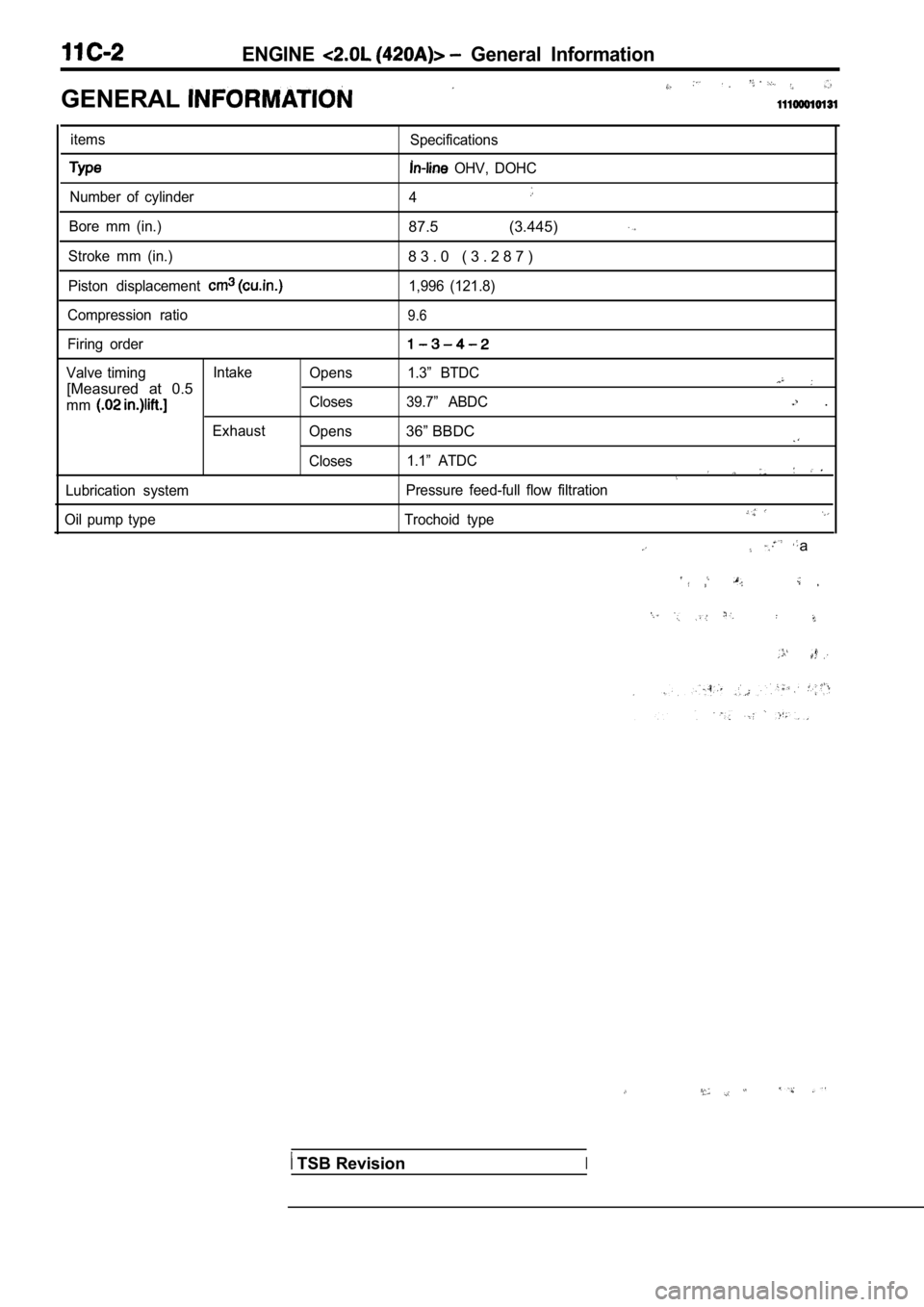
ENGINE General Information
GENERAL
itemsSpecifications
OHV, DOHC
Number of cylinder 4
Bore mm (in.)87.5 (3.445)
Stroke mm (in.)8 3 . 0 ( 3 . 2 8 7 )
Piston displacement 1,996 (121.8)
Compression ratio
9.6
Firing order
Valve timing Intake
Opens 1.3” BTDC
[Measured at 0.5
mmCloses 39.7” ABDC .
Exhaust Opens36” BBDC
Closes 1.1” ATDC
Lubrication system Pressure feed-full flow filtration
Oil pump type Trochoid type
a
TSB RevisionI
Page 177 of 2103
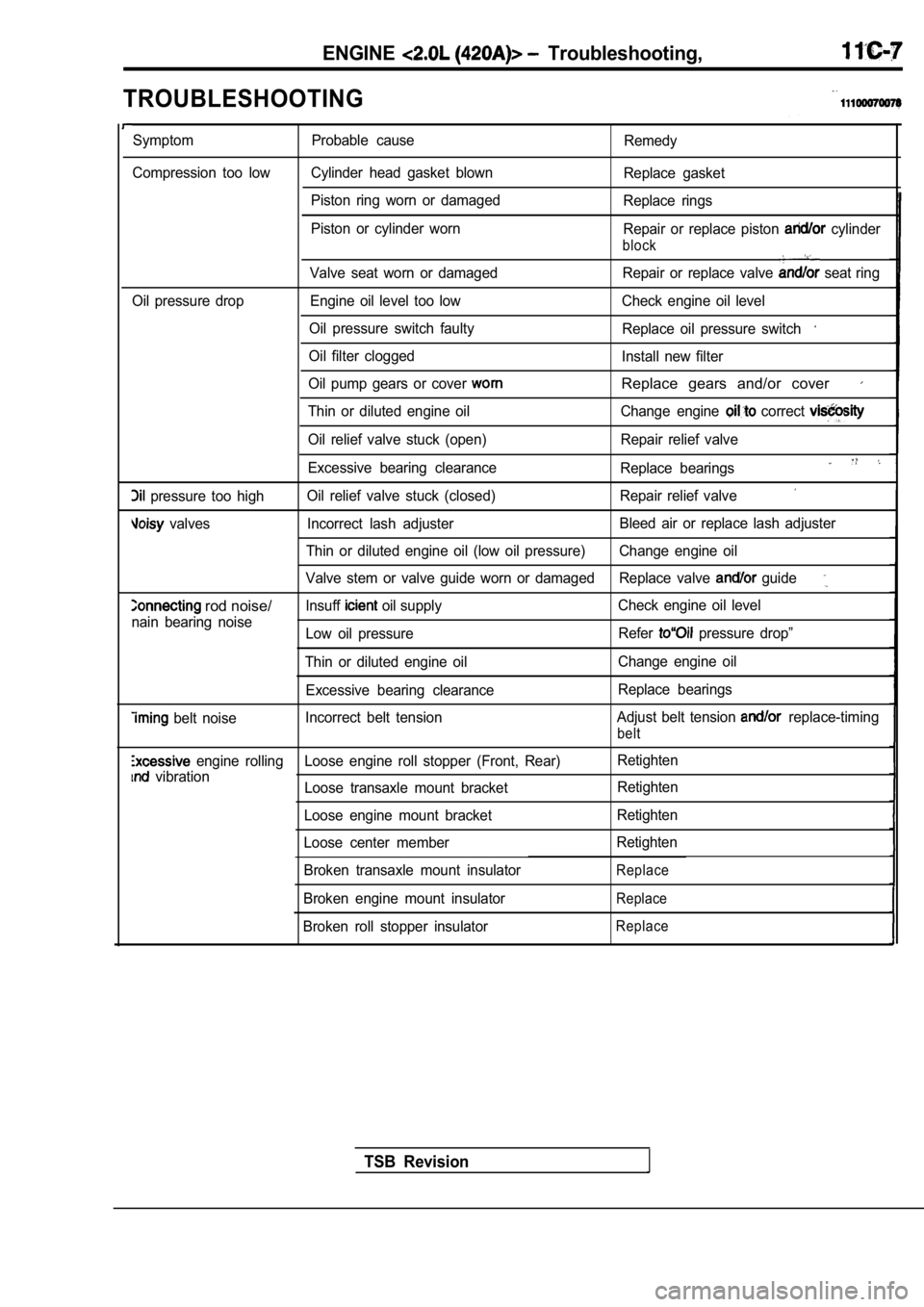
ENGINE Troubleshooting,
TROUBLESHOOTING
Symptom Probable causeRemedy
Compression too low Cylinder head gasket blown Replace gasket
Piston ring worn or damaged Replace rings
Piston or cylinder worn Repair or replace piston
cylinder
block
Valve seat worn or damaged Repair or replace valve seat ring
Oil pressure drop Engine oil level too low Check engi ne oil level
Oil pressure switch faulty Replace oil pressure switch
Oil filter clogged
Install new filter
Oil pump gears or cover
Replace gears and/or cover
Thin or diluted engine oil Change engine correct
Oil relief valve stuck (open) Repair relief valve
Excessive bearing clearance Replace bearings
pressure too highOil relief valve stuck (closed) Repair relief valve
valves Incorrect lash adjuster Bleed air or replace lash adjuster
Thin or diluted engine oil (low oil pressure) Change engine oil
Valve stem or valve guide worn or damaged Replace va lve
guide
rod noise/lnsuff oil supplyCheck engine oil level
nain bearing noise Low oil pressure Refer
pressure drop”
Thin or diluted engine oil Change engine oil
Excessive bearing clearance Replace bearings
belt noiseIncorrect belt tension
Adjust belt tension replace-timing
belt
engine rolling Loose engine roll stopper (Front, Re
ar)Retighten
vibration
Loose transaxle mount bracket Retighten
Loose engine mount bracket Retighten
Loose center member Retighten
Broken transaxle mount insulator
Replace
Broken engine mount insulatorReplace
Broken roll stopper insulatorReplace
TSB Revision