1990 MITSUBISHI SPYDER fuse
[x] Cancel search: fusePage 3 of 2103
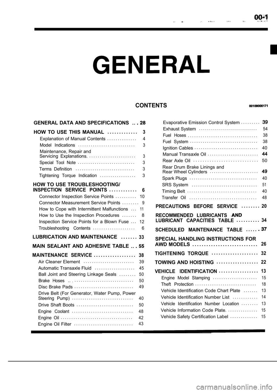
CONTENTS
GENERAL DATA AND SPECIFICATIONS. .
HOW TO USE THIS MANUAL. . . . . . . . . . . . .3
Explanation of Manual Contents. . . . . . . . . . . . . .4
Model Indications
. . . . . . . . . . . . . . . . . . . . . . . . . . .3
Maintenance, Repair and
Servicing Explanations. . . . . . . . . . . . . . . . . . . . . . .
3
Special Tool Note. . . . . . . . . . . . . . . . . . . . . . . . . . .3
Terms Definition. . . . . . . . . . . . . . . . . . . . . . . . . . . .3
Tightening Torque Indication. . . . . . . . . . . . . . . . .3
HOW TO USE TROUBLESHOOTING/
INSPECTION SERVICE POINTS. . . . . . . . . . . .6
Connector Inspection Service Points
. . . . . . . . . .10
Connector Measurement Service Points . . . . . . . .9
How to Cope with Intermittent Malfunctions . . .11
How to Use the Inspection Procedures
. . . . . . .
8
Inspection Service Points for a Blown Fuse . . .
12
Troubleshooting Contents. . . . . . . . . . . . . . . . . . . .6
LUBRICATION AND MAINTENANCE . . . . . . .33
MAIN SEALANT AND ADHESIVE TABLE
. .
MAINTENANCE SERVICE. . . . . . . . . . . . . . . . . .38
Air Cleaner Element. . . . . . . . . . . . . . . . . . . . . . . .39
Automatic Transaxle Fluid
. . . . . . . . . . . . . . . . . . .45
Ball Joint and Steering Linkage Seals
. . . . . . . .50
Brake Hoses.... . . . . . . . . . . . . . . . . . . . . . . . . . . .50
Disc Brake Pads. . . . . . . . . . . . . . . . . . . . . . . . . . . .49
Drive Belt (For Generator, Water Pump, Power
Steering Pump). . . . . . . . . . . . . . . . . . . . . . . . . . . . .40
Drive Shaft Boots
. . . . . . . . . . . . . . . . . . . . . . . . . . .50
Engine Coolant. . . . . . . . . . . . . . . . . . . . . . . . . . . . .48
Engine Oil. . . . . . . . . . . . . . . . . . . . . . . . . . . . . . . . . .42
Engine Oil Filter. . . . . . . . . . . . . . . . . . . . . . . . . . . .43
Evaporative Emission Control System . . . . . . . . .
Exhaust System. . . . . . . . . . . . . . . . . . . . . . . . . . . . .54
Fuel Hoses. . . . . . . . . . . . . . . . . . . . . . . . . . . . . . . . .38
Fuel System. . . . . . . . . . . . . . . . . . . . . . . . . . . . . . . .38
Ignition Cables. . . . . . . . . . . . . . . . . . . . . . . . . . . . . .
40
Manual Transaxle Oil . . . . . . . . . . . . . . . . . . . . . . . .
Rear Axle Oil. . . . . . . . . . . . . . . . . . . . . . . . . . . .
50
Rear Drum Brake Linings and
Rear Wheel Cylinders . . . . . . . . . . . . . . . . . . . . . . .
Spark Plugs. . . . . . . . . . . . . . . . . . . . . . . . . . . . . . . .40
SRS System . . . . . . . . . . . . . . . . . . . . . . . . . . . . . . .51
Timing Belt. . . . . . . . . . . . . . . . . . . . . . . . . . . . . . . . .40
Transfer Oil. . . . . . . . . . . . . . . . . . . . . . . . . . . . . . . .48
PRECAUTIONS BEFORE SERVICE. . . . . . . .20
RECOMMENDED LUBRICANTS
LUBRICANT CAPACITIES TABLE. . . . . . . . . .34
SCHEDULED MAINTENANCE TABLE. . . . .
SPECIAL HANDLING INSTRUCTIONS FOR
AWD MODELS . . . . . . . . . . . . . . . . . . . . . . . . . . . .
26
TIGHTENING TORQUE. . . . . . . . . . . . . . . . . . . .32
TOWING AND HOISTING . . . . . . . . . . . . . . . . . .22
VEHICLE IDENTIFICATION. . . . . . . . . . . . . . . . .13
Engine Model Stamping. . . . . . . . . . . . . . . . . . . . .15
Theft Protection. . . . . . . . . . . . . . . . . . . . . . . . . . . . .18
Vehicle Identification Code Chart Plate
. . . . . . .13
Vehicle Identification Number List. . . . . . . . . . . .14
Vehicle Identification Number Location. . . . . . . .13
Vehicle Information Code Plate.. . . . . . . . . . . . . .15
Vehicle Safety Certification Label
. . . . . . . . . . . . .15
Page 10 of 2103
GENERAL How to Use Service
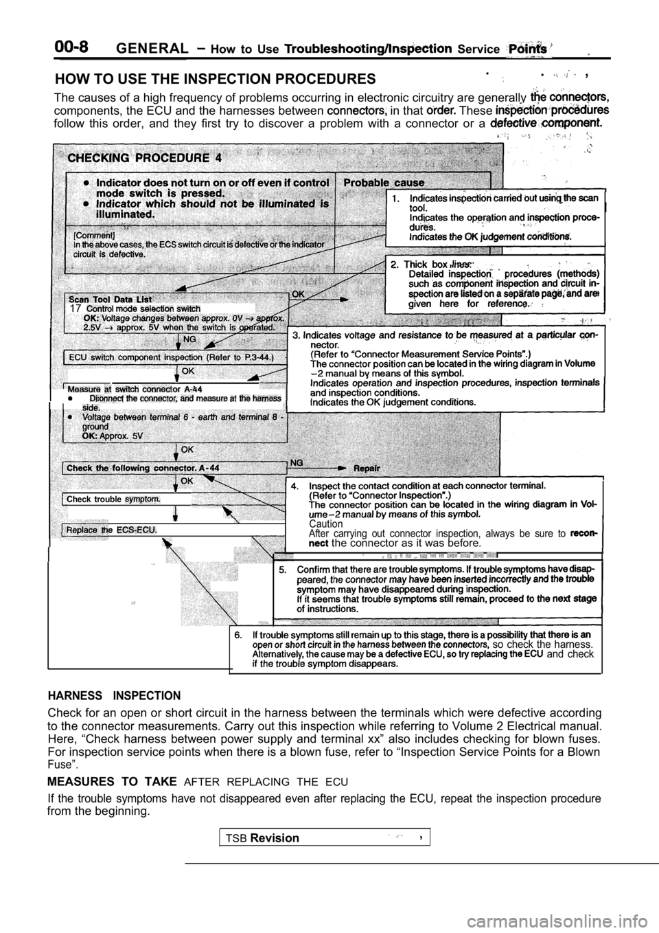
HOW TO USE THE INSPECTION PROCEDURES.. ,
The causes of a high frequency of problems occurrin g in electronic circuitry are generally
components, the ECU and the harnesses between in that These
follow this order, and they first try to discover a problem with a connector or a
17
Check trouble
I
CautionAfter carrying out connector inspection, always be sure to the connector as it was before.
so check the harness. and check
HARNESS INSPECTION
Check for an open or short circuit in the harness b etween the terminals which were defective according
to the connector measurements. Carry out this inspe ction while referring to Volume 2 Electrical manual.
Here, “Check harness between power supply and termi nal xx” also includes checking for blown fuses.
For inspection service points when there is a blown fuse, refer to “Inspection Service Points for a Blown
Fuse”.
MEASURES TO TAKE AFTER REPLACING THE ECU
If the trouble symptoms have not disappeared even a fter replacing the ECU, repeat the inspection procedure
from the beginning.
TSBRevision
,
Page 14 of 2103
GENERAL How to Use Troubleshooting/Inspection
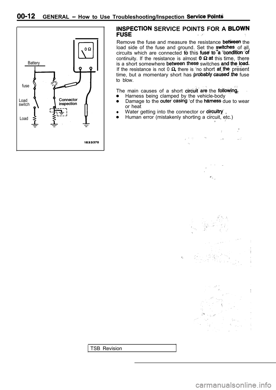
SERVICE POINTS FOR A
Remove the fuse and measure the resistance the
load side of the fuse and ground. Set the of all,
circuits which are connected
this
continuity. If the resistance is almost this time, thereBatteryis a short somewhere switches
IIf the resistance is not 0 there is ‘no short present
time, but a momentary short has fuse
to blow.
fuse
The main causes of a short the .
Harness being clamped by the vehicle-bodyLoadswitchDamage to the ‘of the due to wear
or heat
lWater getting into the connector or ,
LoadHuman error (mistakenly shorting a circuit, etc.) ,
TSB Revision
Page 84 of 2103
ENGINECamshaft and Camshaft Oil
Plastic hammer
sideExhaust side
Slits01
Dowel pins
ExhaustsideIntake side
I
REMOVAL SERVICE POINTS .
EX H A UST
CAMSHAFT SPROCKET
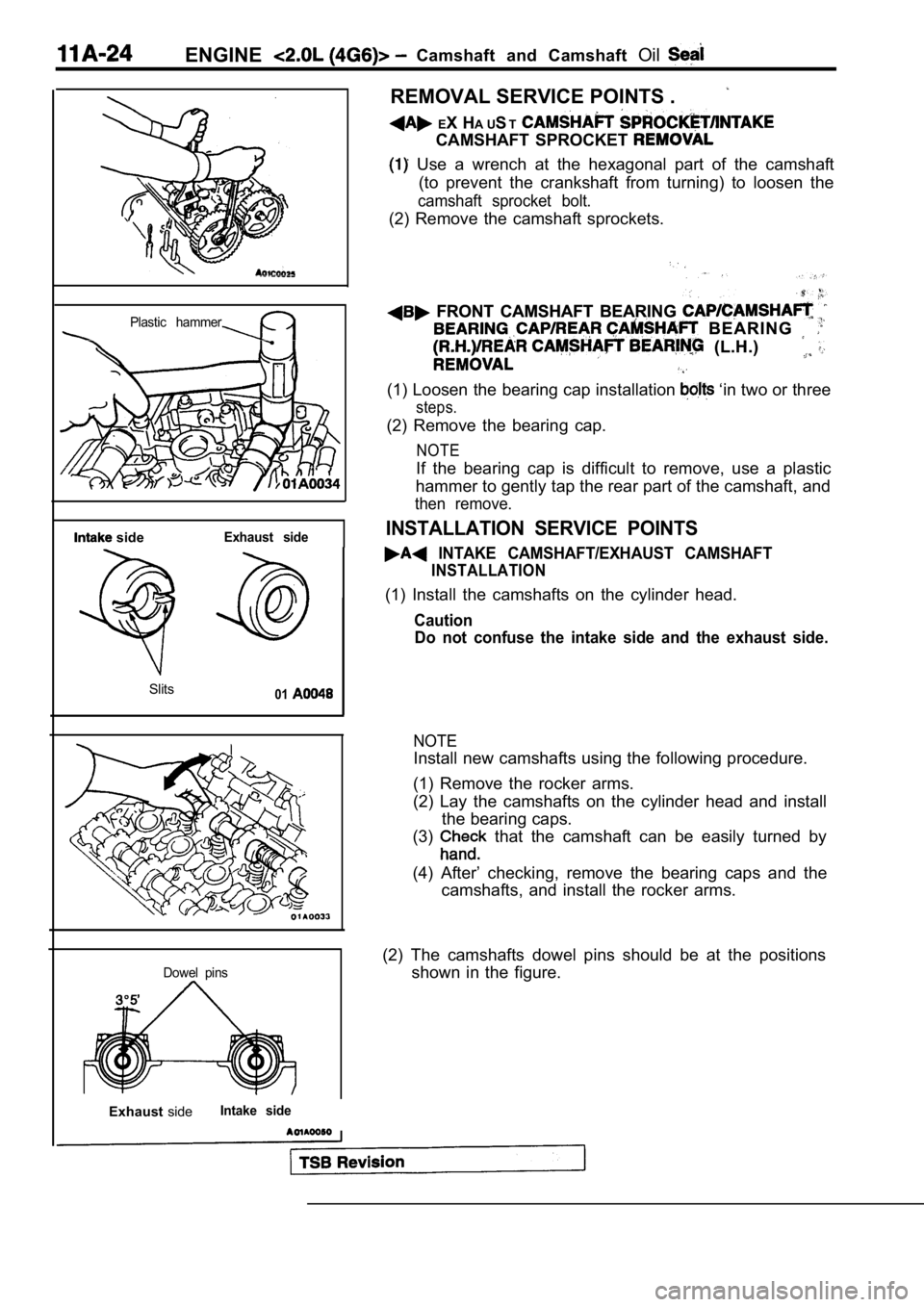
Use a wrench at the hexagonal part of the camshaft
(to prevent the crankshaft from turning) to loosen the
camshaft sprocket bolt.
(2) Remove the camshaft sprockets.
FRONT CAMSHAFT BEARING FRONT CAMSHAFT BEARING
B E A R I N G B E A R I N G
(L.H.) (L.H.)
(1) Loosen the bearing cap installation ‘in two or three
steps.
(2) Remove the bearing cap.
NOTE
If the bearing cap is difficult to remove, use a plastic
hammer to gently tap the rear part of the camshaft, and
then remove.
INSTALLATION SERVICE POINTS
INTAKE CAMSHAFT/EXHAUST CAMSHAFT
INSTALLATION
(1) Install the camshafts on the cylinder head.
Caution
Do not confuse the intake side and the exhaust side .
NOTE
Install new camshafts using the following procedure.
(1) Remove the rocker arms.
(2) Lay the camshafts on the cylinder head and inst all
the bearing caps.
(3)
that the camshaft can be easily turned by
(4) After’ checking, remove the bearing caps and th e
camshafts, and install the rocker arms.
(2) The camshafts dowel pins should be at the posit ions
shown in the figure.
Page 136 of 2103
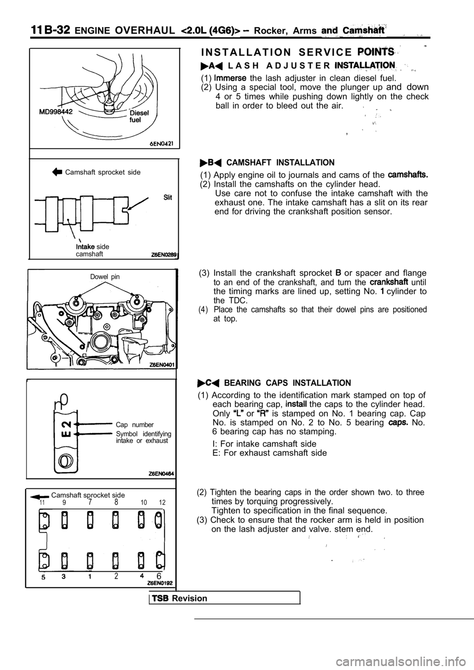
ENGINE OVERHAUL Rocker, Arms
Camshaft sprocket side
sidecamshaft
Dowel pin
n0
Cap number
Symbol identifying
intake or exhaust
0
Camshaft sprocket side1197 810 12
2 6
I N S T A L L A T I O N S E R V I C E
L A S H A D J U S T E R
(1) the lash adjuster in clean diesel fuel.
(2) Using a special tool, move the plunger up and down
4 or 5 times while pushing down lightly on the chec k
ball in order to bleed out the air.
,
CAMSHAFT INSTALLATION
(1) Apply engine oil to journals and cams of the
(2) Install the camshafts on the cylinder head. Use care not to confuse the intake camshaft with th e
exhaust one. The intake camshaft has a slit on its rear
end for driving the crankshaft position sensor.
(3) Install the crankshaft sprocket
or spacer and flange
to an end of the crankshaft, and turn the until
the timing marks are lined up, setting No. cylinder to
the TDC.
(4)Place the camshafts so that their dowel pins are po sitioned
at top.
BEARING CAPS INSTALLATION
(1) According to the identification mark stamped on top of
each bearing cap,
the caps to the cylinder head.
Only
or is stamped on No. 1 bearing cap. Cap
No. is stamped on No. 2 to No. 5 bearing
No.
6 bearing cap has no stamping.
I: For intake camshaft side
E: For exhaust camshaft side
(2) Tighten the bearing caps in the order shown two . to three
times by torquing progressively.
Tighten to specification in the final sequence.
(3) Check to ensure that the rocker arm is held in position
on the lash adjuster and valve. stem end.
.
Revision
Page 411 of 2103
![MITSUBISHI SPYDER 1990 Service Repair Manual . .
Scan tool 18
Code
No.
General Circuit
31
[Comment]
Background
lIt is operated asa PCM output providing a switched ground path once the vehicle enters
closed loop operation.
l This DTC MITSUBISHI SPYDER 1990 Service Repair Manual . .
Scan tool 18
Code
No.
General Circuit
31
[Comment]
Background
lIt is operated asa PCM output providing a switched ground path once the vehicle enters
closed loop operation.
l This DTC](/manual-img/19/57345/w960_57345-410.png)
. .
Scan tool 18
Code
No.
General Circuit
31
[Comment]
Background
lIt is operated asa PCM output providing a switched ground path once the vehicle enters
closed loop operation.
l This DTC indicates a short or
condition in the circuit.
Range of Check
Battery voltage: or more
l Ignition switch: ON
Set Condition
lOpen or short circuit is detected in the EVAP purge control solenoid control circuit for
3 seconds.
Open or short control circuit
l Open fused output , l O p e n or solenoid l . . .
Check the evaporative emission NG Replace
(Refer to GROUP 17 Emission Control System.)
OKNG. . .
Check the following connectors: Measure at the evaporative purge solenoid connector
lDisconnect the connector and measure at the harness side.
l Voltage between 1 and ground
(Ignition switch: ON)
OK: Battery positive voltage
/OK
Measure at the PCM connector lDisconnect the connector and measure at the harness side.
l Voltage between 66 and ground
switch: ON) Battery positive
Check the harness wire, between and Repair, if necessary.
NG
Check the harness wire between the and connector. Repair, if necessary.
N G Repair
Check trouble symptom.
NG
Replace the PCM.
Revision
Page 427 of 2103
![MITSUBISHI SPYDER 1990 Service Repair Manual ENGINE (NON-TURBO)> Troubleshooting
Scan tool 44
C o d eNo relay) output
No.General scan tool V o l t a g e a t P C M
42
[Comment]l relay (ASD output openBackgroundl Fused circu MITSUBISHI SPYDER 1990 Service Repair Manual ENGINE (NON-TURBO)> Troubleshooting
Scan tool 44
C o d eNo relay) output
No.General scan tool V o l t a g e a t P C M
42
[Comment]l relay (ASD output openBackgroundl Fused circu](/manual-img/19/57345/w960_57345-426.png)
ENGINE (NON-TURBO)> Troubleshooting
Scan tool 44
C o d eNo relay) output
No.General scan tool V o l t a g e a t P C M
42
[Comment]l relay (ASD output openBackgroundl Fused circuit openlThe PCM senses operation of the relay (ASD relay) by measuring relay voltage.
l relay (ASD reiay) failed .
(If relay turns to ON, voltage is high). l Circuit in faked
.lThis DTC indicates that no voltage is being sensed when the relay (ASD relay) is
being energized.
Range of Check
l Battery voltage: or more ,
l switch: ON
l Unless the engine is cranking
Set Condition
l The relay voltage is low for 1 second.
.
NG Replace
Measure at the
relay (ASD relay) connector lDisconnect the connector and measure at the harness side.
l Voltage between 6 and ground
OK: Battery positive voltage
l Voltage. between 6 and ground
OK: Battery positive voltage
OK
, .
Check the harness wire the relay relay) and,
the fusible link. Repair,
NGCheck the followingconnect Repair
OK
Check trouble symptom.
N G NG
Check the harness wire between the PCM and the relay (ASD Repair
relay) connector.
Check trouble symptom.
the PCM.
NG
TSB Revision
Page 461 of 2103
![MITSUBISHI SPYDER 1990 Service Repair Manual ENGINE (NON-TURBO)>
Scan tool 183
Code General scan tool Evaporative Emission
No.tion Solenoid Circuit
31
[Comment]l Open or short control drcuitBackgroundl Open fused ignition MITSUBISHI SPYDER 1990 Service Repair Manual ENGINE (NON-TURBO)>
Scan tool 183
Code General scan tool Evaporative Emission
No.tion Solenoid Circuit
31
[Comment]l Open or short control drcuitBackgroundl Open fused ignition](/manual-img/19/57345/w960_57345-460.png)
ENGINE (NON-TURBO)>
Scan tool 183
Code General scan tool Evaporative Emission
No.tion Solenoid Circuit
31
[Comment]l Open or short control drcuitBackgroundl Open fused ignition l The PCM provides a switched ground path to the sole noid. Open or shorted solenoid lThis DTC indicates an open or short-circuit condition in the evaporative emission l PCM failed
solenoid control circuit.
Range of Check
l Battery voltage:
or more
l Ignition switch: ON
ConditionlOpen or short circuit is detected in the evaporativ e emission ventilation solenoid for 3seconds.
N GMeasure at the evaporative emission ventilation sol enoid connectorCheck the following connectors:
lDisconnect the connector and measure at the harness side.
l Voltage between 2 and ground
(Ignition switch: ON)
OK: Battery positive voltage
OKCheck the harness wire between ignition switch and emission ventilation solenoid connector. Repair,if
NGMeasure at the PCM connector Check the following connectors: lDisconnect the connector and measure at the harness side.
l Voltage between 77 and ground
(Ignition switch: ON)
OK: Battery positive voltage
OKCheck the harness wire between PCM and emissionventilation solenoid connector. Repair, if necessar y.
Check the following connector: Repair
Check trouble symptom.
N G
Replace the PCM.
TSB Revision