1990 MITSUBISHI SPYDER roof
[x] Cancel search: roofPage 11 of 2103

GENERAL How to Use Troubleshooting/Inspection Service ‘Points
CONNECTOR
Turn the ignition switch to when connecting and discon-
necting the connectors, and turn the ignition switch to ON
when measuring if there are no instructions to the contrary.
IF INSPECTING WITH THE CONNECTOR
CONNECTED
(WITH CIRCUIT IN A CONDITION OF
Waterproof Connectors
Be sure to use the special tool (harness connector) . Never
insert a test probe from the. harness side, because to do
so will reduce the waterproof performance and result in corro-
sion.
Ordinary (non-waterproof) Connectors
Check by inserting the test probe from’. the harness side.
Note that if the connector (control unit, etc.) is too small to
permit insertion of the test probe, it should not b e forced;
use a special tool (the extra-thin probe in the har ness set
for checking) for this purpose.
IF INSPECTING WITH THE CONNECTOR DISCONNECTED,
Use the special tool (inspection harness for
pin
contact pressure in the harness set, for ‘inspectio n).
The inspection harness for connector pin contact pr essure’
should be used. The test probe
be forcibly in-
serted, as it may cause a defective contact.
Caution. .
At time, be careful not to short the connector
with the test probes. To do so may damage the
inside the ECU.
Revision
Page 57 of 2103
GENERAL Main and Adhesive Table
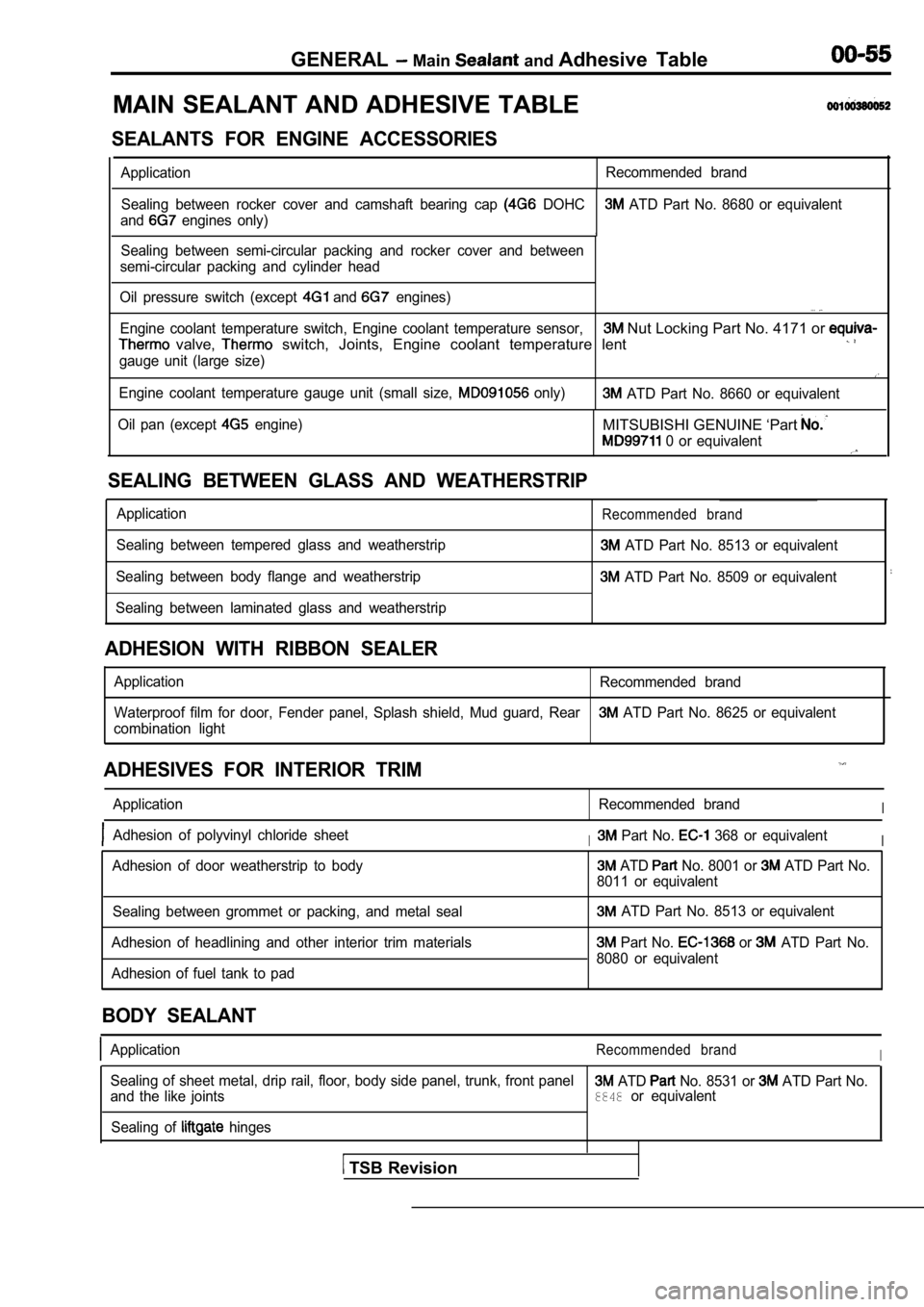
MAIN SEALANT AND ADHESIVE TABLE
SEALANTS FOR ENGINE ACCESSORIES
Application Recommended brand
Sealing between rocker cover and camshaft bearing c ap
DOHC ATD Part No. 8680 or equivalent
and
engines only)
1Sealing between semi-circular packing and rocker co ver and between
semi-circular packing and cylinder head
Oil pressure switch (except
and engines). . .
Engine coolant temperature switch, Engine coolant t emperature sensor, Nut Locking Part No. 4171 or
valve, switch, Joints, Engine coolant temperature lent
gauge unit (large size)
Engine coolant temperature gauge unit (small size, only) ATD Part No. 8660 or equivalent
Oil pan (except
engine)MITSUBISHI GENUINE ‘Part
0 or equivalent
SEALING BETWEEN GLASS AND WEATHERSTRIP
Application
Sealing between tempered glass and weatherstrip
Sealing between body flange and weatherstrip
Sealing between laminated glass and weatherstripRecommended brand
ATD Part No. 8513 or equivalent
ATD Part No. 8509 or equivalent
ADHESION WITH RIBBON SEALER
Application Recommended brand
Waterproof film for door, Fender panel, Splash shie ld, Mud guard, Rear
ATD Part No. 8625 or equivalent
combination light
ADHESIVES FOR INTERIOR TRIM
Application Recommended brandI
Adhesion of polyvinyl chloride sheetI Part No. 368 or equivalentI
Adhesion of door weatherstrip to body ATD No. 8001 or ATD Part No.
8011 or equivalent
Sealing between grommet or packing, and metal seal
Adhesion of headlining and other interior trim mate rials
Adhesion of fuel tank to pad
ATD Part No. 8513 or equivalent
Part No. or ATD Part No.
8080 or equivalent
BODY SEALANT
ApplicationRecommended brandI
Sealing of sheet metal, drip rail, floor, body side panel, trunk, front panel ATD No. 8531 or ATD Part No.
and the like joints8848or equivalent
Sealing of
hinges
TSB Revision
Page 1825 of 2103
CONTENTS
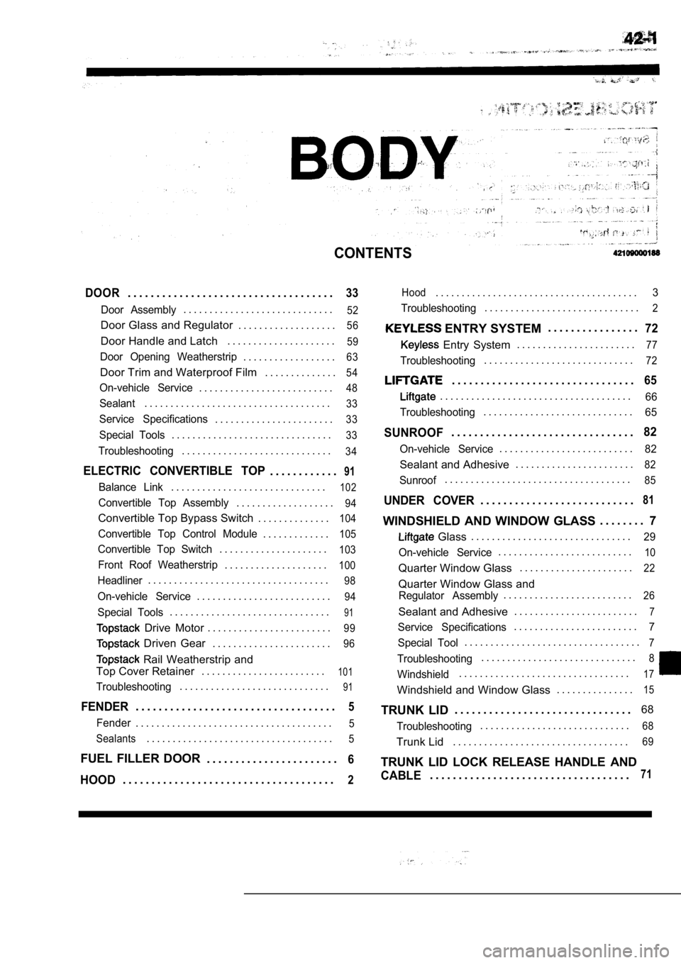
DOOR. . . . . . . . . . . . . . . . . . . . . . . . . . . . . . . . . . . .33
Door Assembly. . . . . . . . . . . . . . . . . . . . . . . . . . . . .52
Door Glass and Regulator . . . . . . . . . . . . . . . . . . .56
Door Handle and Latch. . . . . . . . . . . . . . . . . . . . .59
Door Opening Weatherstrip. . . . . . . . . . . . . . . . . .63
Door Trim and Waterproof Film . . . . . . . . . . . . . .54
On-vehicle Service. . . . . . . . . . . . . . . . . . . . . . . . . .48
Sealant. . . . . . . . . . . . . . . . . . . . . . . . . . . . . . . . . . . .33
Service Specifications. . . . . . . . . . . . . . . . . . . . . . .33
Special Tools. . . . . . . . . . . . . . . . . . . . . . . . . . . . . . .33
Troubleshooting. . . . . . . . . . . . . . . . . . . . . . . . . . . . .34
ELECTRIC CONVERTIBLE TOP. . . . . . . . . . . .91
Balance Link. . . . . . . . . . . . . . . . . . . . . . . . . . . . . .102
Convertible Top Assembly. . . . . . . . . . . . . . . . . . .94
Convertible Top Bypass Switch . . . . . . . . . . . . . .104
Convertible Top Control Module. . . . . . . . . . . . .105
Convertible Top Switch. . . . . . . . . . . . . . . . . . . . .103
Front Roof Weatherstrip. . . . . . . . . . . . . . . . . . . .100
Headliner. . . . . . . . . . . . . . . . . . . . . . . . . . . . . . . . . . .98
On-vehicle Service. . . . . . . . . . . . . . . . . . . . . . . . . .94
Special Tools. . . . . . . . . . . . . . . . . . . . . . . . . . . . . . .91
Drive Motor. . . . . . . . . . . . . . . . . . . . . . . .99
Driven Gear . . . . . . . . . . . . . . . . . . . . . . .96
Rail Weatherstrip and
Top Cover Retainer . . . . . . . . . . . . . . . . . . . . . . . .
101
Troubleshooting. . . . . . . . . . . . . . . . . . . . . . . . . . . . .91
FENDER. . . . . . . . . . . . . . . . . . . . . . . . . . . . . . . . . . .5
Fender. . . . . . . . . . . . . . . . . . . . . . . . . . . . . . . . . . . . . .5
Sealants
. . . . . . . . . . . . . . . . . . . . . . . . . . . . . . . . . . . .5
FUEL FILLER DOOR . . . . . . . . . . . . . . . . . . . . . . .6
HOOD. . . . . . . . . . . . . . . . . . . . . . . . . . . . . . . . . . . . .2
Hood. . . . . . . . . . . . . . . . . . . . . . . . . . . . . . . . . . . . . . .3
Troubleshooting
. . . . . . . . . . . . . . . . . . . . . . . . . . . . . .2
ENTRY SYSTEM . . . . . . . . . . . . . . . .72
Entry System
. . . . . . . . . . . . . . . . . . . . . . .77
Troubleshooting. . . . . . . . . . . . . . . . . . . . . . . . . . . . .72
. . . . . . . . . . . . . . . . . . . . . . . . . . . . . . . .65
. . . . . . . . . . . . . . . . . . . . . . . . . . . . . . . . . . . . .66
Troubleshooting
. . . . . . . . . . . . . . . . . . . . . . . . . . . . .65
SUNROOF. . . . . . . . . . . . . . . . . . . . . . . . . . . . . . . .82
On-vehicle Service. . . . . . . . . . . . . . . . . . . . . . . . . .82
Sealant and Adhesive . . . . . . . . . . . . . . . . . . . . . . .82
Sunroof. . . . . . . . . . . . . . . . . . . . . . . . . . . . . . . . . . . .85
UNDER COVER. . . . . . . . . . . . . . . . . . . . . . . . . . .81
WINDSHIELD AND WINDOW GLASS . . . . . . . .
7
Glass. . . . . . . . . . . . . . . . . . . . . . . . . . . . . . .29
On-vehicle Service
. . . . . . . . . . . . . . . . . . . . . . . . . .10
Quarter Window Glass . . . . . . . . . . . . . . . . . . . . . .22
Quarter Window Glass and
Regulator Assembly. . . . . . . . . . . . . . . . . . . . . . . . .26
Sealant and Adhesive. . . . . . . . . . . . . . . . . . . . . . . .7
Service Specifications. . . . . . . . . . . . . . . . . . . . . . . .7
Special Tool
. . . . . . . . . . . . . . . . . . . . . . . . . . . . . . . . . .7
Troubleshooting. . . . . . . . . . . . . . . . . . . . . . . . . . . . . .8
Windshield. . . . . . . . . . . . . . . . . . . . . . . . . . . . . . . . .17
Windshield and Window Glass . . . . . . . . . . . . . . .15
TRUNK LID. . . . . . . . . . . . . . . . . . . . . . . . . . . . . . . 68
Troubleshooting. . . . . . . . . . . . . . . . . . . . . . . . . . . . .68
Trunk Lid
. . . . . . . . . . . . . . . . . . . . . . . . . . . . . . . . . .69
TRUNK LID LOCK RELEASE HANDLE AND
CABLE. . . . . . . . . . . . . . . . . . . . . . . . . . . . . . . . . . .71
Page 1850 of 2103
BODY Windshield and Window Glass
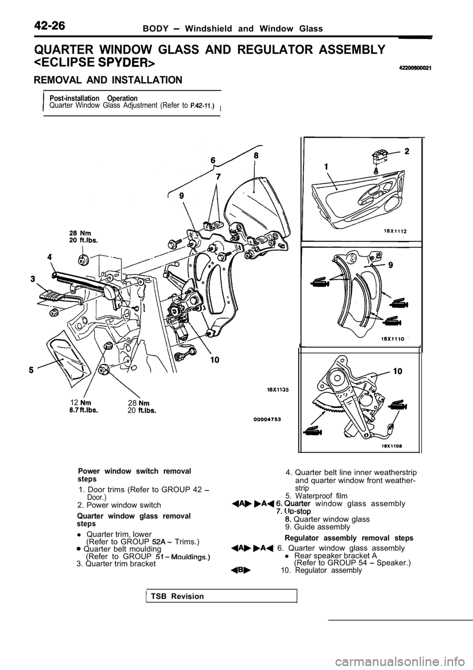
QUARTER WINDOW GLASS AND REGULATOR ASSEMBLY
IPost-installation OperationQuarter Window Glass Adjustment (Refer to I
122820
Power window switch removalsteps
1. Door trims (Refer to GROUP 42 Door.)2. Power window switch
Quarter window glass removalsteps
l Quarter trim, lower
(Refer to GROUP Trims.) Quarter belt moulding (Refer to GROUP
3. Quarter trim bracket
4. Quarter belt line inner weatherstrip
and quarter window front weather-
strip
5. Waterproof film
window glass assembly
Quarter window glass
9. Guide assembly
Regulator assembly removal steps
6. Quarter window glass assembly l Rear speaker bracket A
(Refer to GROUP 54 Speaker.)10. Regulator assembly
TSB Revision
Page 1851 of 2103
BODY Windshield Window
Section A A
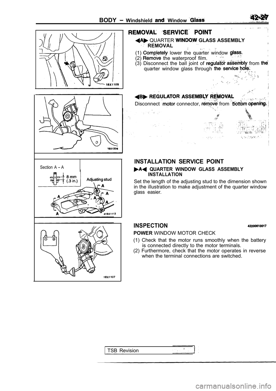
QUARTER GLASS ASSEMBLY
REMOVAL
(1) lower the quarter window
(2) the waterproof film.
(3) Disconnect the ball joint of from
quarter window glass through ,
Disconnect connector, from
INSTALLATION SERVICE POINT
QUARTER WINDOW GLASS ASSEMBLY
INSTALLATION
Set the length of the adjusting stud to the dimension shown
in the illustration to make adjustment of the quart er window
glass easier.
INSPECTION
POWERWINDOW MOTOR CHECK
(1) Check that the motor runs smoothly when the bat tery
is connected directly to the motor terminals.
(2) Furthermore, check that the motor operates in r everse
when the terminal connections are switched.
TSB Revision
Page 1857 of 2103

BODY,
SERVICE SPECIFICATIONS
Items
Inside handle play mm (in.)Standard value .
6.2 or more
Outside handle play mm (in;)
Clearance of door window Adjustment of glass inclin ation
glass to weatherstripamount
holder mm (in.)
Adjustment of glass longitudinal
inclination
Clearance between door window glass and door window glass
catch mm (in.)
Overlap margin between door window glass and door w indow
glass catch mm (in.)
Distance between door window glass and weatherstrip step line
mm (in.)
4.4 more
Front pillar37.0
Roof or convertible3 1
Front pillar
1.6
Roof or convertible1
Quarter pillar
Front pillar
SEALANT
Roof or Convertible 6.3 1
Quarter pillar 13.0 1
Front pillar
R o o f o r C o n v e r t i b l e 1
Front pillar
1.6
Roof or Convertible 1 I
Items Specified sealantII
Waterproof film ATD Part No. 8625 or equivalent
SPECIAL TOOLS
ToolTool number and nameApplication
General service toolRemoval of switch, trim,. etc.
remover
Adjustment of door fit
Door adjusting wrench
TSB Revision
Page 1870 of 2103

BODY Door
GLASS AND DOORS
SymptomProbable causeR e m e d y
Water leak through Incorrect window glass installation
Adjust position
door window glass Gap at upper window glass Adjust position
Door window Incorrect window glass installation
Adjust position
malfunction
Damaged or faulty regulator Correct or replace
Water leak throughCracked or faulty weatherstripReplace
door edge
Water leak from doorDrain hole clogged
Remove foreign objects
centerInadequate waterproof film contact or damageCorrect or replace
Door hard to open Incorrect latch or striker adjustment
Adjust
Door does not open Incorrect door installation Adjust position
close completely
Defective door check strap Correct or replace
Door check strap and hinge require grease Apply grease
Uneven gap betweenIncorrect door installationAdjust position
Wind noise around
door
Weatherstrip not holding firmly Adjust fit of door
Improperly installed weatherstrip or setting of Rep
air or replace
weatherstrip
Improperly closed door Adjust
Improperly fit door Adjust
Improper clearance between door glass and door Adjust
weatherstrip holder
D e f o r m e d d o o rRepair or replaceI
TSB Revision
Page 1872 of 2103
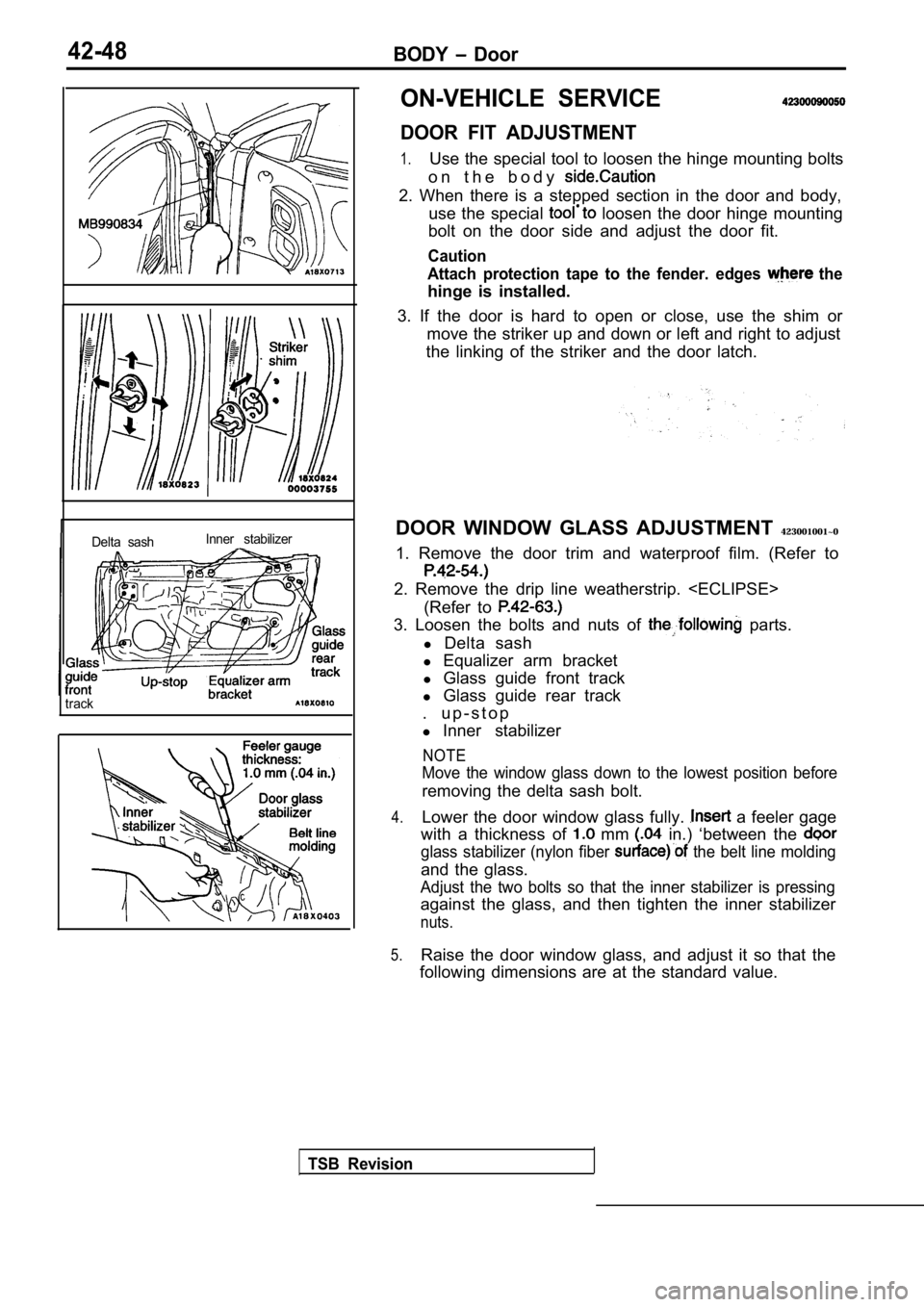
42-48BODY Door
Delta sashInner stabilizer
track
ON-VEHICLE SERVICE
DOOR FIT ADJUSTMENT
1.Use the special tool to loosen the hinge mounting b
olts
o n t h e b o d y
2. When there is a stepped section in the door and body,
use the special
loosen the door hinge mounting
bolt on the door side and adjust the door fit.
Caution
Attach protection tape to the fender. edges
the
hinge is installed.
3. If the door is hard to open or close, use the sh im or
move the striker up and down or left and right to a djust
the linking of the striker and the door latch.
DOOR WINDOW GLASS ADJUSTMENT 423001001~0
1. Remove the door trim and waterproof film. (Refer to
2. Remove the drip line weatherstrip.
(Refer to
3. Loosen the bolts and nuts of parts.
l Delta sash
l Equalizer arm bracket
l Glass guide front track
l Glass guide rear track
. u p - s t o p
l Inner stabilizer
NOTE
Move the window glass down to the lowest position b efore
removing the delta sash bolt.
4.Lower the door window glass fully. a feeler gage
with a thickness of
mm in.) ‘between the
glass stabilizer (nylon fiber the belt line molding
and the glass.
Adjust the two bolts so that the inner stabilizer i s pressing
against the glass, and then tighten the inner stabi lizer
nuts.
5.Raise the door window glass, and adjust it so that the
following dimensions are at the standard value.
TSB Revision