1990 MITSUBISHI SPYDER clutch
[x] Cancel search: clutchPage 29 of 2103
GENERAL Special Handling Instructions for Models
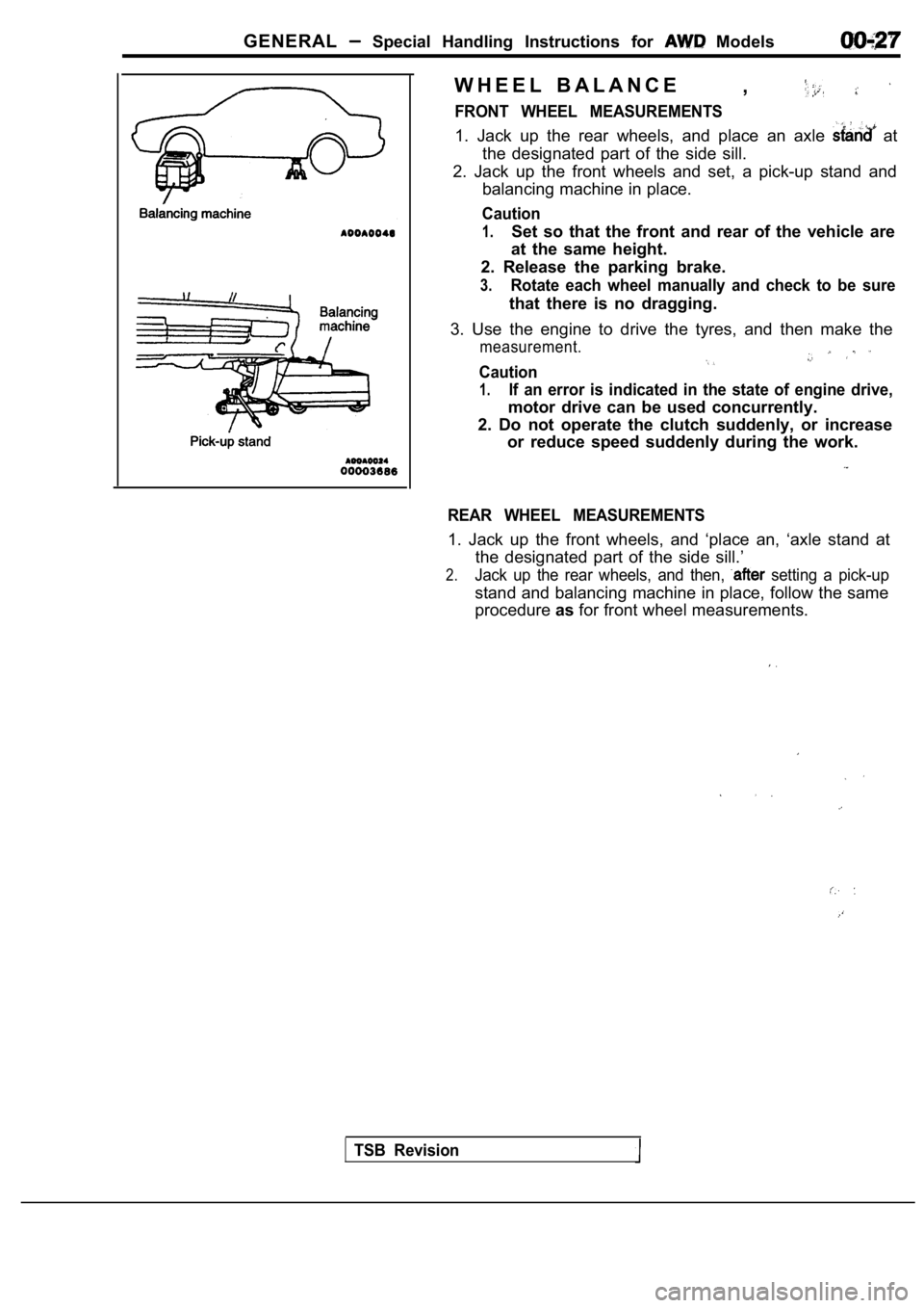
W H E E L B A L A N C E,
FRONT WHEEL MEASUREMENTS
1. Jack up the rear wheels, and place an axle at
the designated part of the side sill.
2. Jack up the front wheels and set, a pick-up stan d and
balancing machine in place.
Caution
1.Set so that the front and rear of the vehicle are
at the same height.
2. Release the parking brake.
3.Rotate each wheel manually and check to be sure
that there is no dragging.
3. Use the engine to drive the tyres, and then make the
measurement.
Caution
1.If an error is indicated in the state of engine drive,
motor drive can be used concurrently.
2. Do not operate the clutch suddenly, or increase or reduce speed suddenly during the work.
REAR WHEEL MEASUREMENTS
1. Jack up the front wheels, and ‘place an, ‘axle s tand at
the designated part of the side sill.’
2.Jack up the rear wheels, and then, setting a pick-up
stand and balancing machine in place, follow the sa me
procedure asfor front wheel measurements.
TSB Revision
Page 36 of 2103
Lubrication and
GENERAL Lubricants and Lubricant Capacities Table
Use of fuels containing alcohol is not recommended
unless the nature of the blend can be determined
as being satisfactory.
Gasohol
A mixture of 10% ethanol (grain alcohol)
and 90% unleaded gasoline may be used in your
car.
If problems are experienced as a result
of using gasohol, it is recommended that the car
be operated on gasoline.
Methanol Do not use gasolines containing
methanol (wood alcohol). Use of this type of alcohol
can result in vehicle performance deterioration and
damage critical parts in the fuel system compo-
nents. Fuel system damage and performance prob-
lems, resulting from the use of gasolines containin g
methanol, may not be covered by the new car war-
ranty.
Gasolines containing
Ether)
Unleaded gasoline containing 15% or
may be used in car. Fuel containing MTBE
over 15% vol. may cause reduced engine perfor-
mance and produce vapor lock or hard starting.
MATERIALS
TO FUEL
Indiscriminate use of fuel system -cleaning’
should be avoided. Many of these materials in-
tended for gum and varnish removal
highly active solvents or similar ingredients that
can be harmful to gasket and diaphragm materials
used in fuel system component
RECOMMENDED LUBRICANTS
Items
Engine
Recommended lubricants
Engine oil displaying EOLCS certification mark or c onforming
to the API classification SH or (For
details, refer to section)
Manual transaxle Engine (Non-turbo) TEXACO MTX FLUID FM I
Engine (Turbo) and API classification SAE or
Engine,
Automatic transaxle DIAMOND ATF SP or equivalent
TSB Revision
Transfer API classification SAE or
Differential (rear axle)API classification or higher
Above SAE
From to
SAE
Below SAE
Power steering
Brake and clutch Automatic transmission fluid
Conforming to or
Engine coolant LONG-LIFE COOLANT (Part or
High quality ethylene-glycol antifreeze I
Page 48 of 2103
GENERAL Maintenance
4.Before removing dipstick, wipe all dirt from area around
dipstick. Then take out the dipstick and check the condition
of the fluid.
Further investigation of the transaxle is necessary if,
l the fluid smells burnt.
l the fluid color is brown or black.
l metal particles can be seen or felt on the dipstick .
5.Check to see if fluid level is in “HOT” range on dipstick.
If fluid level is low, add ATF until level reaches “HOT”
range. Low fluid level can cause a variety of condi tions
because it allows pump to take in air along with fl uid.
Air trapped in hydraulic circuit forms bubbles which make
fluid spongy.
Therefore, pressures will be erratic. Improper filling can also raise fluid level too hig h. When
transaxle has too much fluid, gears churn up foam a nd
cause same conditions which occur with low fluid le vel,
resulting in accelerated deterioration of ATF.
In either case, air bubbles can cause overheating, fluid
-oxidation, which can interfere with normal valve, clutch,
and servo operation. Foaming can also result in flu id
escaping from transaxle vent where it may be mistak en
for a leak.
6. Be sure to examine fluid on dipstick closely.
(Change fluid)
Engine (Non-turbo)>
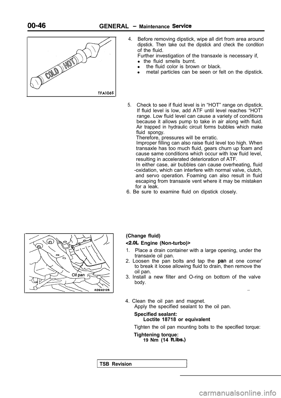
1.Place a drain container with a large opening, under the
transaxle oil pan.
2. Loosen the pan bolts and tap the
at one comer’
to break it loose allowing fluid to drain, then rem ove the
oil pan.
3. Install a new filter and O-ring on bottom of the valve
body.
4. Clean the oil pan and magnet.
Apply the specified sealant to the oil pan.
Specified sealant: Loctite 18718 or equivalent
Tighten the oil pan mounting bolts to the specified torque:
Tightening torque:
19Nm (14
TSB Revision
Page 197 of 2103
ENGINE Crankshaft Rear Oil Seal
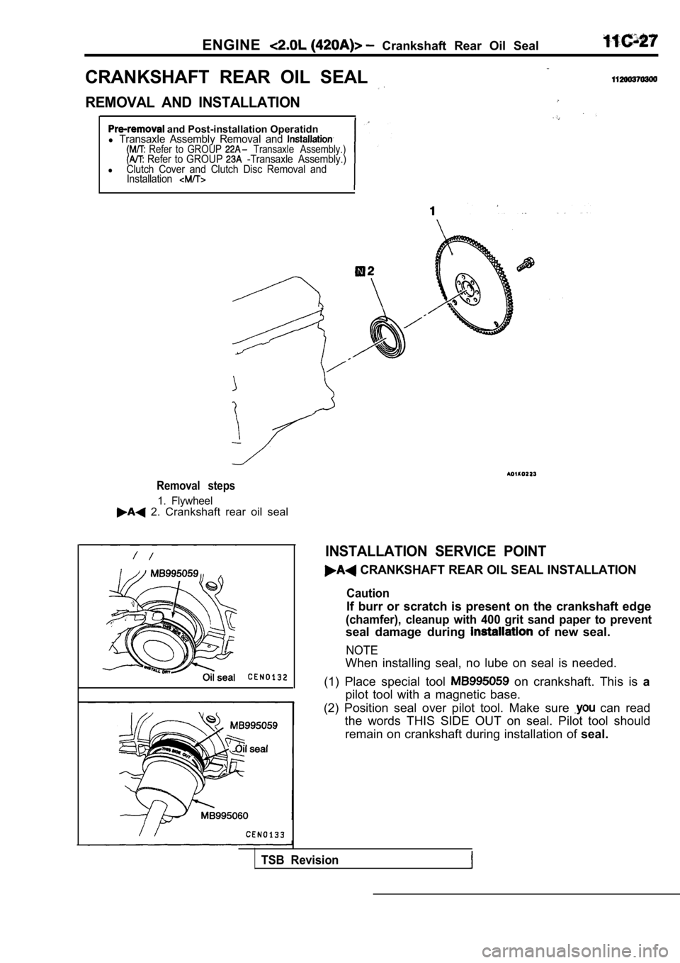
CRANKSHAFT REAR OIL SEAL
REMOVAL AND INSTALLATION
and Post-installation Operatidnl Transaxle Assembly Removal and Refer to GROUP Transaxle Assembly.) Refer to GROUP -Transaxle Assembly.)lClutch Cover and Clutch Disc Removal and Installation
Removal steps
1. Flywheel 2. Crankshaft rear oil seal
INSTALLATION SERVICE POINT
CRANKSHAFT REAR OIL SEAL INSTALLATION
Caution
If burr or scratch is present on the crankshaft edg e
(chamfer), cleanup with 400 grit sand paper to prev ent
seal damage during of new seal.
NOTE
When installing seal, no lube on seal is needed.
(1) Place special tool
on crankshaft. This is a
pilot tool with a magnetic base.
(2) Position seal over pilot tool. Make sure
can read
the words THIS SIDE OUT on seal. Pilot tool should
remain on crankshaft during installation of seal.
TSB Revision
Page 295 of 2103
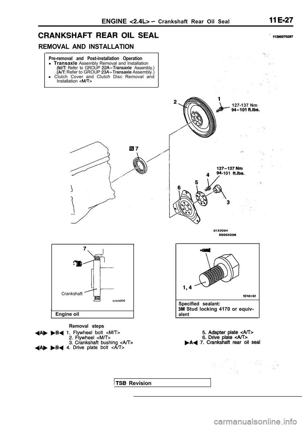
ENGINECrankshaft Rear Oil Seal
REMOVAL AND INSTALLATION
Pre-removal and Post-installation Operationl Transaxle Assembly Removal and Installation Refer to GROUP Assembly.) Refer to GROUP Assembly.)
l Clutch Cover and Clutch Disc Removal and
Installation
127-137 Nm
-101
Crankshaft
Engine oil
Removal steps
Specified sealant:
Stud locking 4170 or equiv-
alent
Revision
Page 384 of 2103
ENGINE (NON-TURBO)>
DIAGNOSTIC TEST MODE
l When an abnormality is detected in one
of the sensors or actuators related to
emission control, the CHECK
MALFUNCTION INDICATOR LAMP
nates as a warning to the driver.
l When an abnormality is detected in one
of the sensors or actuators, a diagnostic
OTHER CONTROL FUNCTIONS
t r o u b l e c o d e
a b n o r m a l i t y i s o u t p u t .
lThe RAM data inside the PCM that is
to the sensors and
by means of the scan tool.
In addition, the actuators can be controlled
under certain circumstances. . ,
1. Fuel Pump Control
Turns the fuel pump relay ON so that current
is supplied to the fuel pump while the engine
is cranking or running.
2. A/C Compressor Clutch Relay Control Turns the A/C compressor clutch ON and
OFF.
3. Fan Relay Control
The radiator fan and condenser fan speeds
are controlled in response to the engine
coolant temperature and vehicle speed. 4. Generator
Controls the generator in order
to control the generated current.
5. Engine Speedometer or Tachometer
Control.
Sends a pulse signal which ‘corresponds
to the engine speed to the’ speedometer
unit..
6. Evaporative Emission Purge
C o n t r o l
Refer to GROUP 17.
7. Electric EGR Transducer Solenoid Control Refer to GROUP 17.
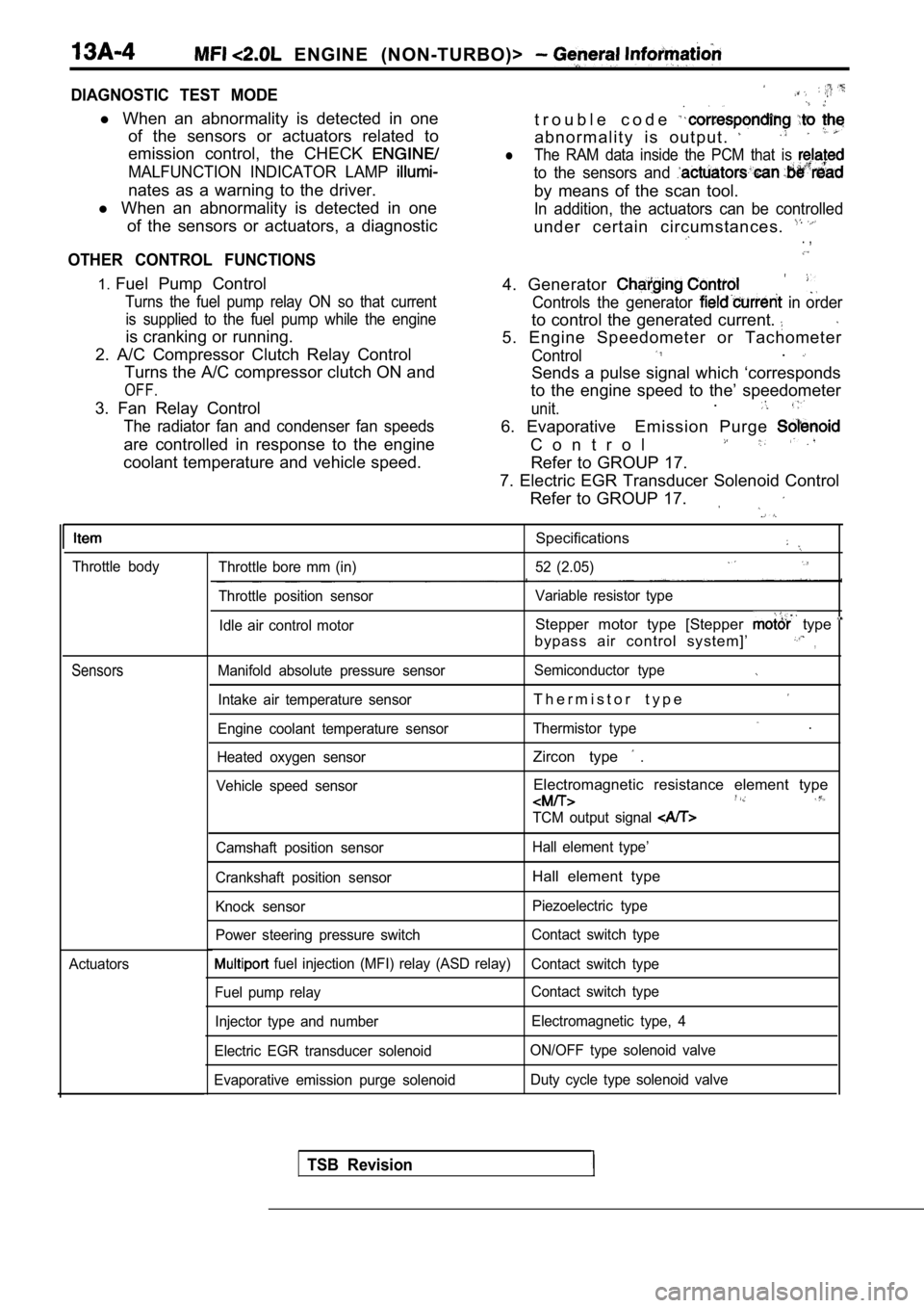
Throttle body
Sensors
Actuators
Specifications
Throttle bore mm (in) 52 (2.05)
Throttle position sensor Variable resistor type
Idle air control motor
Stepper motor type [Stepper type
bypass air control system]’,
Manifold absolute pressure sensor Semiconductor type
Intake air temperature sensorT h e r m i s t o r t y p e
Engine coolant temperature sensorThermistor type .
Heated oxygen sensorZircon type .
Vehicle speed sensorElectromagnetic resistance element type
TCM output signal
Camshaft position sensor Hall element type’
Crankshaft position sensor
Hall element type
Knock sensor Piezoelectric type
Power steering pressure switch Contact switch type
fuel injection (MFI) relay (ASD relay)
Contact switch type
Fuel pump relay Contact switch type
Injector type and number Electromagnetic type, 4
Electric EGR transducer solenoid ON/OFF type solenoid valve
Evaporative emission purge solenoid Duty cycle type solenoid valve
TSB Revision
Page 398 of 2103
ENGINE (NON-TURBO)> Troubleshooting
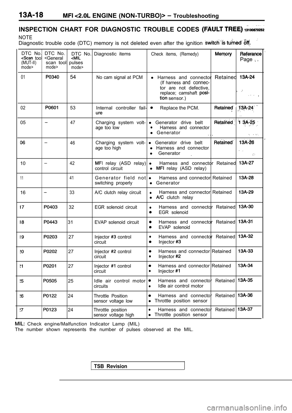
INSPECTION CHART FOR DIAGNOSTIC TROUBLE CODES
NOTE
Diagnostic trouble code (DTC) memory is not deleted even after the ignition
DTC No. DTC No.
DTC No. Diagnostic itemsCheck items, (Remedy) tool
mode>
mode>
01 54No cam signal at PCMl Harness and connector Retained
(If harness and connec-
tor are not defective,
replace; camshaft ,
sensor.) ,
02 53
Internal controller fail- Replace the PCM.,
. .
0547
46
Charging system volt- l Generator drive belt
age too lowlHarness and connector
l Generator. . ,
Charging system volt- l Generator drive belt
age too highl Harness and connector
l Generator
1042
1 141
1633
relay (ASD relay) lHarness and connector Retained
control circuitl relay (ASD relay)
G e n e r a t o r f i e l d n o t lHarness and connector Retained
switching properlyl Generator
A/C clutch relay circuitlHarness and connector Retained
l clutch relay
32
31
27
27
27
25
24
24
EGR solenoid circuitlHarness and connector Retained
EGR solenoid
EVAP solenoid circuit
Harness and connector Retained
EVAP solenoid
Injector
controllHarness and connector Retained
circuitInjector
Injector controlHarness and connector Retained
circuitlInjector
Injector controlHarness and connector Retained
circuitlInjector
Idle air control motor Harness and connector Retained
circuitslIdle air control motor
Throttle PositionHarness and connector Retained
sensor voltage lowl Throttle position sensor
Throttle positionlHarness and connector Retained
sensor voltage highl Throttle position sensor
TSB Revision
Check engine/Malfunction Indicator Lamp (MIL)
The number shown represents the number of pulses ob served at the MIL.
Page 409 of 2103
![MITSUBISHI SPYDER 1990 Service Repair Manual Scan tool 16
General scan tool A/C Clutch Relay Circuit ,.
33
[Comment]Coinpressor clutch relay shortedBackgroundl control circuit defectivel The PCM provides a switched groun MITSUBISHI SPYDER 1990 Service Repair Manual Scan tool 16
General scan tool A/C Clutch Relay Circuit ,.
33
[Comment]Coinpressor clutch relay shortedBackgroundl control circuit defectivel The PCM provides a switched groun](/manual-img/19/57345/w960_57345-408.png)
Scan tool 16
General scan tool A/C Clutch Relay Circuit ,.
33
[Comment]Coinpressor clutch relay shortedBackgroundl control circuit defectivel The PCM provides a switched ground to the clutch relay.
l circuit driver in PCMlThe PCM can prevent operation of the clutch in selected situations such as duringwide-open or for a period at start-up.l This DTC indicates an open or short-circuit conditi on in the circuit.Range of Checkl Ignition ONl Battery voltage: or morel 30 seconds or more after starting engineSet ConditionlOpen or short circuit is detected in the A/C clutch relay control circuit for 3 seconds.
N G relay. Replace
. .
. 55 On-vehicle Service) me (Refer to GROUF
OK
Measure at the PCM connectors and lDisconnect the connector, and measure at the harnes s side.
l Voltage between 36 and ground, and 64 and ground
(Ignition switch: ON)
switch: ON)
OK: Battery positive
l Connect a jumper wire between and the ground.
(Ignition switch: ON)
(A/C switch: ON)
OK:
compressor clutch is turned on
N G
Check the system (Refer to GROUP 55 Troubleshooting) Check trouble symptom.
NG
Replace the . ,
I ,
TSB Revision