1990 MITSUBISHI SPYDER clutch
[x] Cancel search: clutchPage 523 of 2103

ENGINE (TURBO)
AND ENGINE> General lnformaiton
Engine>
Heated oxygen sensor Power supply(front)l Vehicle speed sensor Volume air flow sensor l switch Intake air temperature Park/neutral positionsensorswitch Throttle position sensor Power steering pressure Closed throttle positionswitch
switchl Ignition switch ST Camshaft position sensor Crankshaft position sen-sor Barometric pressure sen-sor Engine coolant tempera-
ture sensor
valve position sensor Heated oxygen sensor(rear) Manifold differential pres-sure sensor tank differential pres-
sure sensor
,
Engine control Injector l
Fuel pump relay Evaporative emission lFuel pump relay purge solenoid air control motor injection EGR solenoid relay Evaporative emission l ventilation solenoid clutch relay
l C h e c k
o u t p u t coil, ignition
T h r o t t l e s e n s o r ,
control
Intake air
t e m p e r a t u r e
. . . sensor pressure
a
temperature sensor EGR
solenoidHeated oxygen
Fuel tank pressure
sensor (rear) Heated oxygen
Evaporativeemission canisterFuel tank
Crankshaft position sensor
Camshaft positionsensor
TSB Revision
Page 533 of 2103
ENGINE (TURBO)
AND
ENGINE> Troubleshooting
4. Exhaust gas recirculation (EGR) system monitor
Test conditions/procedure
1. All of the following conditions should be satisfied when the drive test is carried out.
(1) Engine coolant temperature:
or higher (when engine is
(2) Outside air temperature: or higher
(3) A/T condition:
lSelector lever position: range
l Overdrive switch: ON
lPower/economy changeover switch: Power
(4) A/C switch:
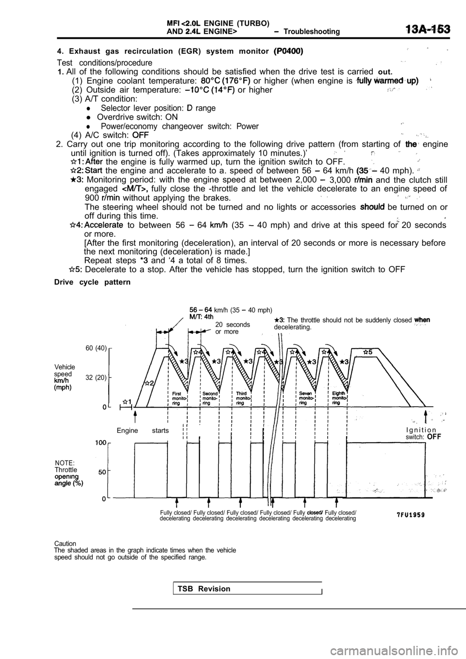
2. Carry out one trip monitoring according to the f ollowing drive pattern (from starting of engine
until ignition is turned off). (Takes approximately 10 minutes.)’
the engine is fully warmed up, turn the ignition s witch to OFF.
the engine and accelerate to a. speed of between 5 6 64 km/h 40 mph).
Monitoring period: with the engine speed at between 2,000 3,000 and the clutch still
engaged
fully close the -throttle and let the vehicle dece lerate to an engine speed of
900
without applying the brakes.
The steering wheel should not be turned and no ligh ts or accessories be turned on or
off during this time.
to between 56 64 (35 40 mph) and drive at this speed for 20 seconds
or more.
[After the first monitoring (deceleration), an inte rval of 20 seconds or more is necessary before
the next monitoring (deceleration) is made.]
Repeat steps
and ‘4 a total of 8 times.
Decelerate to a stop. After the vehicle has stoppe d, turn the ignition switch to OFF
Drive cycle pattern
60 (40)
Vehicle
speed
32 (20)
NOTE:Throttle
km/h (35 40 mph)
20 seconds
The throttle should not be suddenly closed
or more decelerating.
Engine starts I g n i t i o nswitch:OFF
Fully closed/ Fully closed/ Fully closed/ Fully clo
sed/ Fully Fully closed/
decelerating decelerating decelerating decelerating decelerating decelerating
TSB RevisionI
Caution
The shaded areas in the graph indicate times when t he vehicle
speed should not go outside of the specified range.
Page 541 of 2103
ENGINE (TURBO)
AND
ENGINE> Troubleshooting
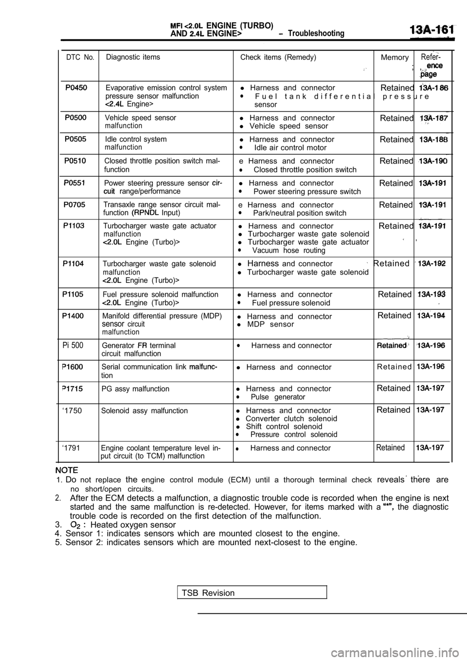
DTC No.Diagnostic items Check items (Remedy)MemoryRefer-
; ,
Evaporative emission control systeml Harness and connector
Retained
pressure sensor malfunctionl
Engine>F u e l t a n k d i f f e r e n t i a l p r e s s u r e
sensor
Vehicle speed sensorl Harness and connectormalfunctionl Vehicle speed sensor Retained
Idle control systeml
Harness and connector
RetainedmalfunctionlIdle air control motor
Closed throttle position switch mal-e Harness and connector Retained
functionlClosed throttle position switch
Power steering pressure sensor l Harness and connector
Retained
range/performancelPower steering pressure switch
Transaxle range sensor circuit mal-e Harness and connector Retainedfunction Input)lPark/neutral position switch
Turbocharger waste gate actuatorl Harness and connector
Retained
malfunctionl Turbocharger waste gate solenoid
Engine (Turbo)>l Turbocharger waste gate actuator ,
lVacuum hose routing
Turbocharger waste gate solenoidl Harness and connector Retained
malfunctionl Turbocharger waste gate solenoid
Engine (Turbo)>
Fuel pressure solenoid malfunctionl Harness and connector
Retained
Engine (Turbo)>lFuel pressure solenoid
Manifold differential pressure (MDP)l Harness and connector Retainedsensorcircuitl
MDP sensormalfunction
Pi 500Generator terminal
circuit malfunctionlHarness and connector
Serial communication link
tion
l Harness and connector R e t a i n e d
‘1750
‘1791PG assy malfunction
l
Harness and connector RetainedlPulse generator
Solenoid assy malfunction
l Harness and connector Retained
l
Converter clutch solenoid
l Shift control solenoid
lPressure control solenoid
Engine coolant temperature level in-
lHarness and connectorRetained
put circuit (to TCM) malfunction
1. Do not replace theengine control module (ECM) until a thorough termin al check reveals there are
no short/open circuits.
2.After the ECM detects a malfunction, a diagnostic t rouble code is recorded when the engine is next
started and the same malfunction is re-detected. Ho wever, for items marked with a the diagnostic
trouble code is recorded on the first detection of the malfunction.
3.
Heated oxygen sensor
4. Sensor 1: indicates sensors which are mounted cl osest to the engine.
5. Sensor 2: indicates sensors which are mounted ne xt-closest to the engine.
TSB Revision
Page 577 of 2103
ENGINE
AND ENGINE> Troubleshooting
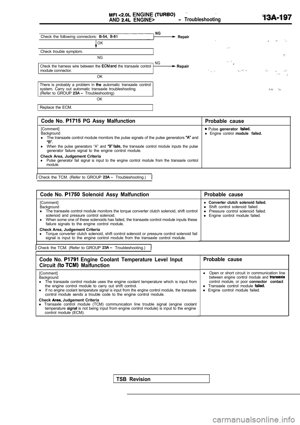
NGCheck the following connectors: Repair
OK
Check trouble symptom.
NG
NGCheck the harness wire between the the transaxle control Repairmodule connector. ,
OK
There is probably a problem in automatic transaxle control
system. Carry out automatic transaxle troubleshooti ng.
(Refer to GROUP Troubleshooting)
OK
Replace the ECM.
Code No. PG Assy Malfunction
Probable cause
[Comment] Pulse generatorBackgroundl Engine control module failed.lThe transaxle control module monitors the pulse sig nals of the pulse generators and
lWhen the pulse generators “A” and the transaxle control module inputs the pulsegenerator failure signal to the engine control modu le.
Check Area, Judgement Criteria
lPulse generator fail signal is input to the engine control module from the transaxle control
module.
Check the TCM. (Refer to GROUP Troubleshooting.)
Code No. Solenoid Assy Malfunction Probable cause
[Comment]
Background
lThe transaxle control module monitors the torque co nverter clutch solenoid, shift control
solenoid and pressure control solenoid.
lWhen some one of these solenoids has failed, the tr ansaxle control module inputs these
failure signals to the engine control module.
Check Area, Judgement Criteria
lTorque converter clutch solenoid, shift control sol enoid or pressure control solenoid fail
signal is input to the engine control module from t he transaxle control module.
Check the TCM. (Refer to GROUP Troubleshooting.)
l Converter clutch solenoid failed.l Shift control solenoid failed.
l Pressure control solenoid failed.
l Engine control module failed.
Code No. Engine Coolant Temperature Level Input
Circuit
Malfunction
[Comment]
Background
lThe transaxle control module uses the engine coolan t temperature which is input from
the engine control module to carry out shift contro l.
lIf no engine coolant temperature signal is input from the engine control module, the transaxlecontrol module sends a trouble code to the engine c ontrol module.
Check
Judgement Criteria
l Transaxle control module (TCM) communication line t rouble signal (engine coolant
temperature
is not being input from engine control module) is input to the engine
control module (ECM).
Probable cause
lOpen or short circuit in communication linebetween engine control module and control module, or poor connector contactl Transaxle control module l Engine control module failed.
TSB Revision
Page 587 of 2103
![MITSUBISHI SPYDER 1990 Service Repair Manual ENGINE (TURBO)
AND Troubleshooting
INSPECTION PROCEDURE 9
speed is high. (Improper idle speed)
[Comment]
In such cases as the above, the cause is probably that the intake ai MITSUBISHI SPYDER 1990 Service Repair Manual ENGINE (TURBO)
AND Troubleshooting
INSPECTION PROCEDURE 9
speed is high. (Improper idle speed)
[Comment]
In such cases as the above, the cause is probably that the intake ai](/manual-img/19/57345/w960_57345-586.png)
ENGINE (TURBO)
AND Troubleshooting
INSPECTION PROCEDURE 9
speed is high. (Improper idle speed)
[Comment]
In such cases as the above, the cause is probably that the intake air volume during idle is too
great.
YES
Refer to INSPECTION CHART FOR Are diagnostic troublecodesoutputTROUBLE CODES.
Check the idle air control motor for operation sound Engine (Turbo)>. (Refer to Check the idle air control motor for operation sound Engine>. (Refer to
OKCheck the idle control system malfunction (Refer
INSPECTION PROCEDURE FOR DIAGNOSTIC TROUBLE CODE
NGSCAN TOOL Data list Check the closed throttle position 26 Closed throttle position switch (Refer to (Refer to INSPECTION PROCEDURE FOR TROUBLE CODE
SCAN TOOL Data listNG Check the engine coolant’ temperature 21 I N S P E C T I O N
P R O C E D U RE
OKTROUBLE CODES
SCAN TOOL Data list
28 A/C switch (Refer to
OK
Adjust the basic idle speed. (Refer to
Check the A/C switch and clutch to INSPECTION PROCEDURE 32.)
Check trouble symptom.
N G
Clean the throttle valve area. (Refer to
Check and the fixed SAS. (Refer to .
TSB RevisionI
Page 604 of 2103
![MITSUBISHI SPYDER 1990 Service Repair Manual E N G I N E
AND ‘ENGINE> Troubleshooting
INSPECTION PROCEDURE 32
switch and compressor clutch relay system, . .
(Comment]l Malfunction of control When an A/C ON signal is i MITSUBISHI SPYDER 1990 Service Repair Manual E N G I N E
AND ‘ENGINE> Troubleshooting
INSPECTION PROCEDURE 32
switch and compressor clutch relay system, . .
(Comment]l Malfunction of control When an A/C ON signal is i](/manual-img/19/57345/w960_57345-603.png)
E N G I N E
AND ‘ENGINE> Troubleshooting
INSPECTION PROCEDURE 32
switch and compressor clutch relay system, . .
(Comment]l Malfunction of control When an A/C ON signal is input to the the ECM carries out control of the idle air control Malfunction of motor, and also operates the compressor magnetic clutch.lImproper connector open circuit or harness .
NG
(Refer toGROUP55 On-vehicleService.) Replace
OK
Measure at the ECM connectors lDisconnect the connector, and measure at the harness
lVoltage between 22 and ground, and 45 and ground
(Ignition switch: ON)
(A/C switch: ON)
OK: Battery positive voltage
l Shortcircuit between 22 and ground
(Ignition switch: ON)
switch: ON)
OK: compressor clutch turns ON.
OK
N G
OK
Check trouble symptom.
the
NG
TSB RevisionI
Page 622 of 2103
E N G I N E
AND ENGINE>. . .
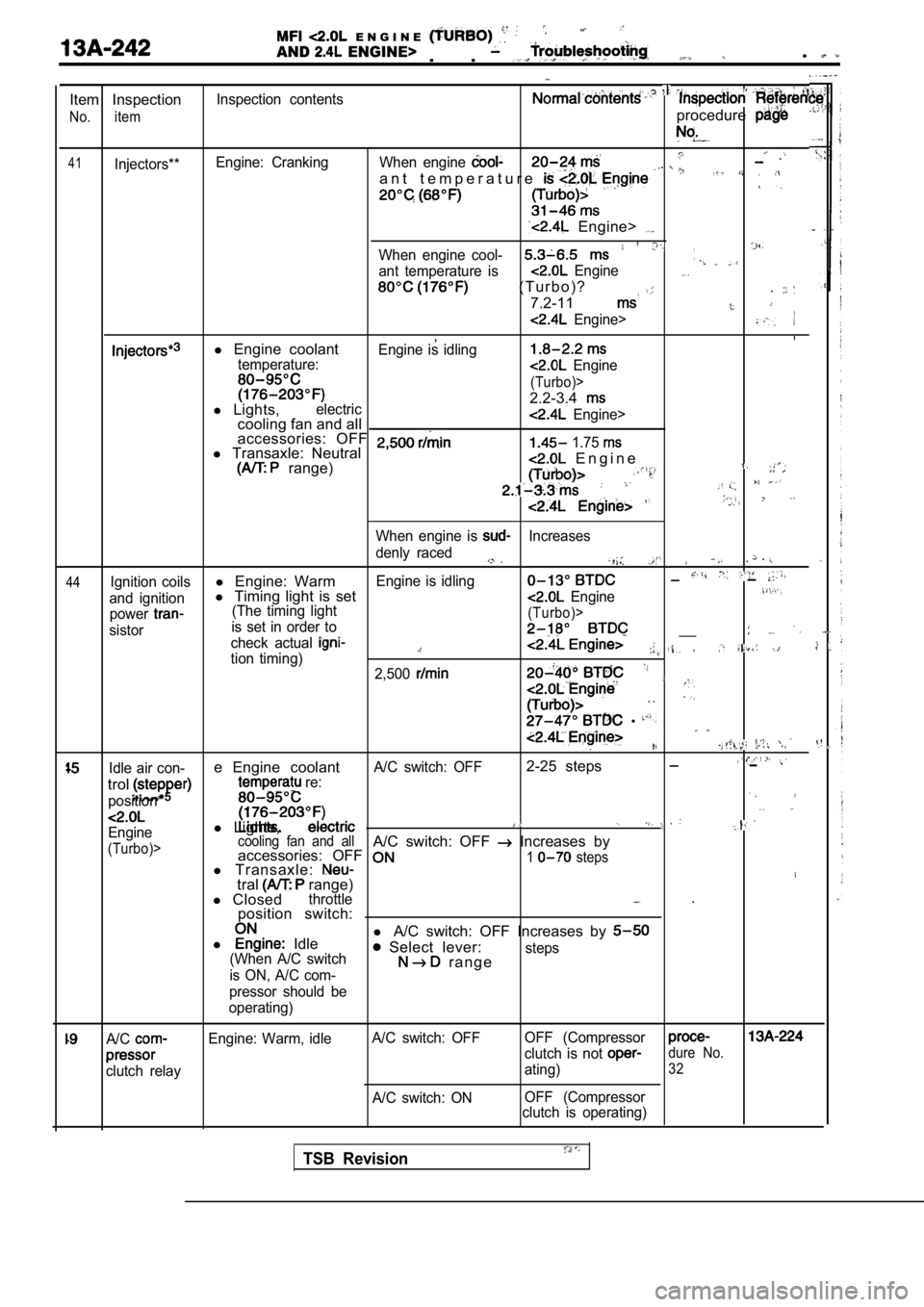
Item Inspection
No. item
41Injectors**Inspection contents
Engine: Cranking
procedure
When engine
a n t t e m p e r a t u r e
Engine>
When engine cool-
ant temperature is Engine
( T u r b o ) ?
7.2-11
.
Engine>
,l Engine coolantEngine is idlingtemperature: Engine
(Turbo)>
2.2-3.4l Lights,electriccooling fan and all Engine>
accessories: OFF l Transaxle: Neutral 1.75
range) E n g i n e
44
When engine is Increases
denly raced
.
Ignition coilsl Engine: WarmEngine is idling
and ignitionl Timing light is set Engine
power(The timing light
sistor is set in order to(Turbo)>
check actual __
tion timing)2,500
. .
.
,
Idle air con-e Engine coolantA/C switch: OFF2-25 steps
trol
position*
re:
l
Lights,Engine
(Turbo)> cooling fan and allA/C switch: OFF Increases by
accessories: OFF
l Transaxle:1 steps
tral range)
l Closedthrottle .
position switch:
l
Idle l
A/C switch: OFF Increases by Select lever:(When A/C switch
is ON, A/C com- r a n g esteps
pressor should be
operating)
A/C
clutch relay Engine: Warm, idle
A/C switch: OFF
A/C switch: ON OFF (Compressor
clutch is not dure No.
ating)32
OFF (Compressor
clutch is operating)
TSB Revision
Page 627 of 2103
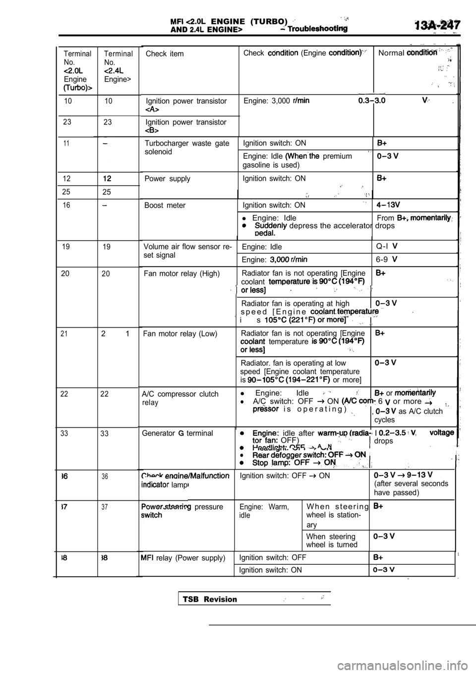
ENGINE (TURBO)
AND ENGINE>
Check itemIgnition power transistorCheck (Engine Normal
Engine: 3,000 .
Ignition power transistor
Terminal No.
Engine
Terminal
No.
Engine>
10 10
23 23
11
12
Turbocharger waste gate Ignition switch: ON
solenoid
Engine: Idle premium
gasoline is used)
Power supply Ignition switch: ON
2525
Boost meter
Ignition switch: ON
l Engine: IdleFrom depress the accelerator drops
16
19
19Volume air flow sensor re- Engine: IdleQ - l
set signal
Engine:6-9
Fan motor relay (High)Radiator fan is not operating [Engine
coolant
2020
21
22
33
.
Radiator fan is operating at high
s p e e d [ E n g i n e
i s
Fan motor relay (Low)Radiator fan is not operating [Engine temperature
Radiator. fan is operating at low
speed [Engine coolant temperature
is
or more]
A/C compressor clutch
l Engine: Idle or
relaylA/C switch: OFF ON 6 or more i s o p e r a t i n g ) , as A/C clutch
cycles
2 1
22
33
ine: idle after I OFF) . . A Ndrops
II. .
Generator terminal
l
36Ignition switch: OFF ON
lamp(after several seconds
have passed)
pressureEngine: Warm,W h e n s t e e r i n g
idlewheel is station-
ary
When steering
wheel is turned
37
relay (Power supply) Ignition switch: OFF
Ignition switch: ON
TSB Revision