Page 834 of 2103

C L U T C H
21199979939
SymptomProbable cause
Remedy
Clutch slips Insufficient clutch pedal play Adjust
Excessive wear of clutch disc facing
Replace
Hardening of clutch disc facing, or adhesion of oilReplace
Clutch release fork catching Repair or replace parts
Weak or damaged diaphragm spring
Replace
Clogging of hydraulic systemRepair or replace parts
Gear shift malfunction Excessive clutch pedal Adjust
Distorted clutch disc, excessive oscillation
Replace
Clutch cover assembly wornReplace
Clutch disc spline worn or corrodedReplace
Clutch disc facing peelingReplace
Clutch bearing wornReplace
Damaged pressure plate or flywheelReplace
Leakage, air mix or clogging of hydraulic system Repair or replace parts
noise clutch pedal playAdjust
Improper installation of clutch cover assembly Repair or replace parts
Excessive wear of clutch disc facing
Replace
Clutch release fork catching Repair or replace parts
Clutch release bearing worn
Replace
Weak or damaged torsion springReplace
Damaged pilot bushingReplace
Insufficient lubrication of bearing sleeve sliding Repair
surface
pedal feels Insufficient lubrication of clutch ped alRepair
Insufficient lubrication of clutch disc spline Repai r
Clutch release fork catching Repair or replace parts
Insufficient lubrication of bearing sleeve sliding
Repair
or damaged Worn or damaged clutch disc facing
disc facing
Oil adhered to clutch disc facing
Uneven
of diaphragm spring
Weak or damaged torsion spring Damaged pressure plate or flywheel
Loose or damaged mounting
Replace
Replace
Repair or replace parts
Replace
Replace
Replace or tighten mounting
Revision
Page 835 of 2103

CLUTCH -On-vehicle Service
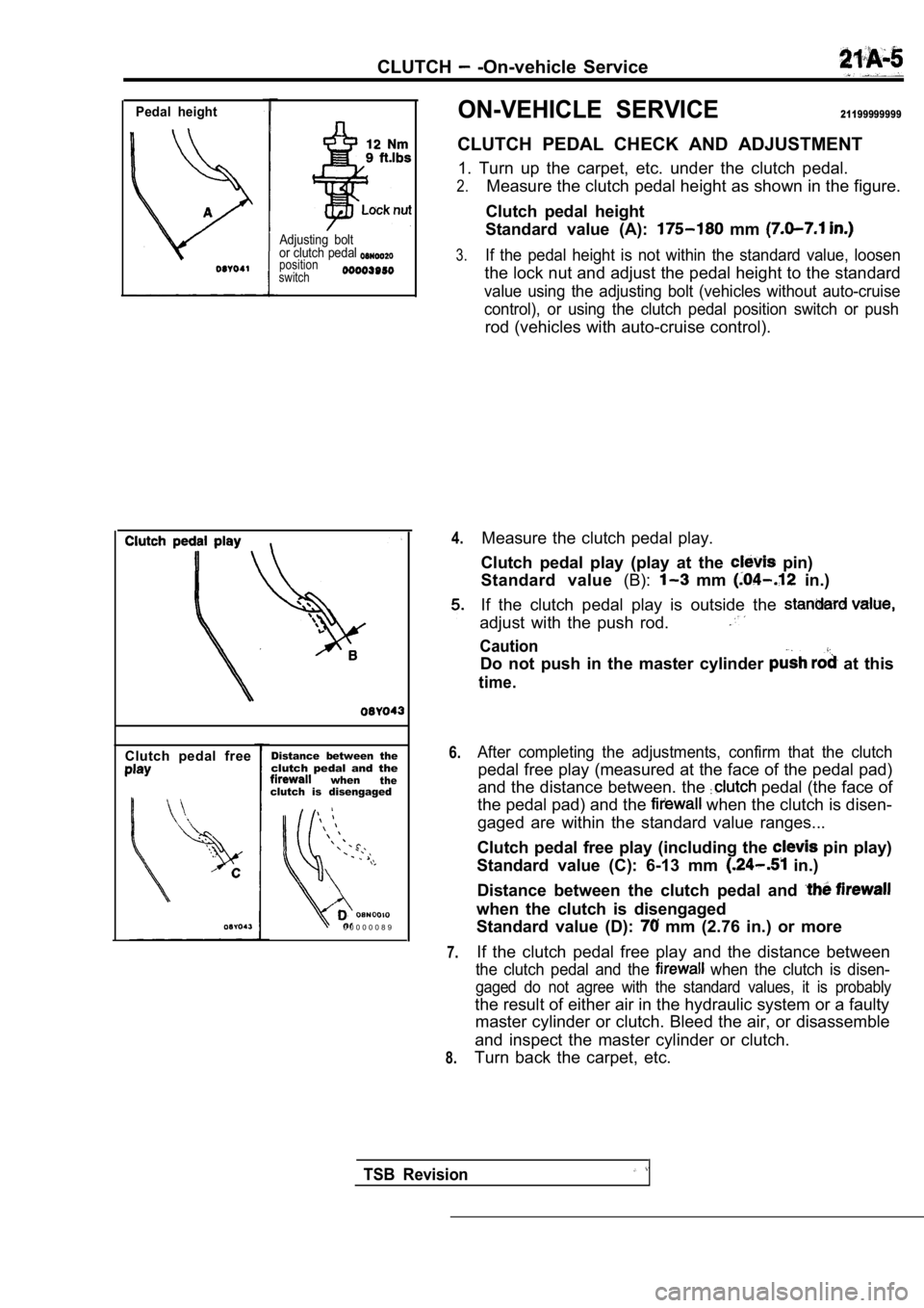
Pedal height
Adjusting bolt
or clutch pedal
position
switch
Clutch pedal freeDistance between theclutch pedal and thewhentheclutch is disengaged
0 0 0 0 0 0 8 9
ON-VEHICLE SERVICE21199999999
CLUTCH PEDAL CHECK AND ADJUSTMENT
1. Turn up the carpet, etc. under the clutch pedal.
2.Measure the clutch pedal height as shown in the fig ure.
Clutch pedal height
Standard value (A):
mm
3.If the pedal height is not within the standard valu e, loosen
the lock nut and adjust the pedal height to the sta ndard
value using the adjusting bolt (vehicles without au to-cruise
control), or using the clutch pedal position switch or push
rod (vehicles with auto-cruise control).
4.
6.
7.
8.
Measure the clutch pedal play.
Clutch pedal play (play at the
pin)
Standard value (B):
mm in.)
If the clutch pedal play is outside the
adjust with the push rod.
Caution
Do not push in the master cylinder at this
time.
After completing the adjustments, confirm that the clutch
pedal free play (measured at the face of the pedal pad)
and the distance between. the
pedal (the face of
the pedal pad) and the
when the clutch is disen-
gaged are within the standard value ranges...
Clutch pedal free play (including the
pin play)
Standard value (C): 6-13 mm
in.)
Distance between the clutch pedal and
when the clutch is disengaged
Standard value (D):
mm (2.76 in.) or more
If the clutch pedal free play and the distance betw een
the clutch pedal and the when the clutch is disen-
gaged do not agree with the standard values, it is probably
the result of either air in the hydraulic system or a faulty
master cylinder or clutch. Bleed the air, or disass emble
and inspect the master cylinder or clutch.
Turn back the carpet, etc.
TSB Revision
Page 836 of 2103

CLUTCH On-vehicle Service
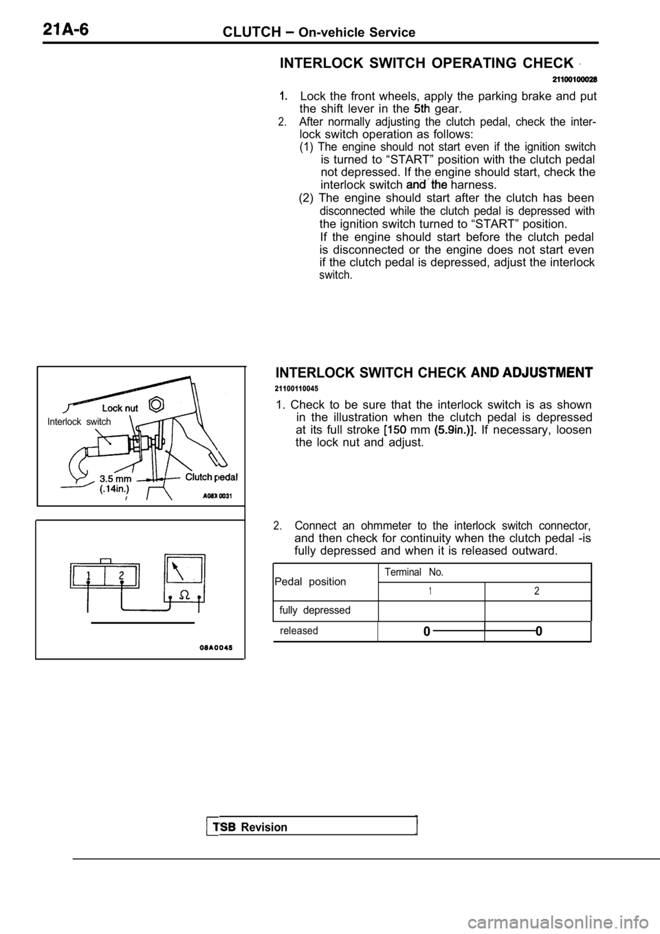
Interlock switch
Revision
INTERLOCK SWITCH OPERATING CHECK
1.
2.
Lock the front wheels, apply the parking brake and put
the shift lever in the
gear.
After normally adjusting the clutch pedal, check th e inter-
lock switch operation as follows:
(1) The engine should not start even if the ignition switch
is turned to “START” position with the clutch pedal
not depressed. If the engine should start, check th e
interlock switch
harness.
(2) The engine should start after the clutch has be en
disconnected while the clutch pedal is depressed with
the ignition switch turned to “START” position.
If the engine should start before the clutch pedal
is disconnected or the engine does not start even
if the clutch pedal is depressed, adjust the interl ock
switch.
INTERLOCK SWITCH CHECK
21100110045
1. Check to be sure that the interlock switch is as shown
in the illustration when the clutch pedal is depres sed
at its full stroke
mm If necessary, loosen
the lock nut and adjust.
2.Connect an ohmmeter to the interlock switch connect or,
and then check for continuity when the clutch pedal -is
fully depressed and when it is released outward.
Terminal No.Pedal position12
fully depressed
released0I0
Page 837 of 2103
CLUTCH On-vehicle Service
Engine (Non-turbo)>
Engine (Turbo) and
BLEEDING
Whenever the clutch tube, the clutch clutch
master cylinder have or the clutch pedal
is spongy, bleed the system.
Specified brake fluid: DOT 3 or 4
Caution
Use only the specified brake fluid. Do not mix with
fluid.
TSB Revision
Page 838 of 2103
21CLUTCH Clutch Pedal
CLUTCH PEDAL
REMOVAL AND INSTALLATION
Pre-removal OperationlScuff Plate Removal GROUP Cowl Side Trim Removal(Refer to GROUP Trims.)
l Junction Block Installation Boll: Removal
Post-installation Operationl Clutch Pedal Adjustment (Refer tol Junction Block Installation
l Cowl Side Trim Installation (Refer to GROUP Trims.) Scuff Plate Installation
(Refer to GROUP Trims.)
I
I
Nm7-929 Nm21
5
Removal steps
1. Instrument under
(Refer to GROUP Panel.)
2. Master cylinder installation nuts
3. Clutch pedal return spring gine (Non-turbo) Engine>4. Clevis pin
5. Clutch pedal assembly
6. Clevis pin
(Turbo)>
7. Rod A Engine (Turbo)>
8. Turnover spring Engine
9. Rod Engine (Turbo)>
Revision
00003519
E n g i n e ( T u r b o ) >
Clutch pedal13. Bushing
14. Spacer
15. Pedal pad
16. Adjusting bolt
17. Clutch pedal position switch
18. Interlock switch
19. Clutch pedal bracket assembly
Page 839 of 2103
CLUTCH Clutch
INSPECTION
l Check the pedal shaft for, wear.
l Check the clutch
‘for
lCheck the return spring for or
lCheck the turnover spring for
lCheck the pedal pad for damage or wear.
TSBRevision
Page 840 of 2103
CLUTCH Clutch Control
CLUTCH CONTROL
REMOVAL AND INSTALLATION
Operationl Clutch Fluid Draining
Engine (Non-turbo)>
Clutch Pedal Adjustment (Refer to
Specified grease:
MITSUBISHI genuine grease
Part No. 0101011 or equivalentI
Nm
11
11
TSB Revision
Clutch master
removalsteps
1. Clevis pin
2. Clutch pipe
3. Clutch master cylinder
4. Sealer
5. Reservoir bracket
49
00003520
Clutch release cylinder removal
steps
6. Clutch pipe connection
7. Clutch release cylinder
Clutch line removal steps 8. Clutch pipe
11. Clutch pipe 12. Clutch hose 13. Clutch hose bracket
Page 841 of 2103
CLUTCH Clutch
Nm7-9 Engine (Turbo)>
,
9
11
Clutch master cylinder removal
steps
1. pin
2. Clutch pipe connection
master cylinder
Reservoir bracket
Clutch release cylinder removal
steps
6. Clutch pipe connection
7. Clutch release cylinder
Clutch line removal steps 8. Clutch pipe
9. Clutch pipe10. Clutch fluid chamber 11. Clutch pipe 12. Clutch h o s e
TSB Revision