Page 903 of 2103

MANUAL TRANSAXLE OVERHAUL Tools
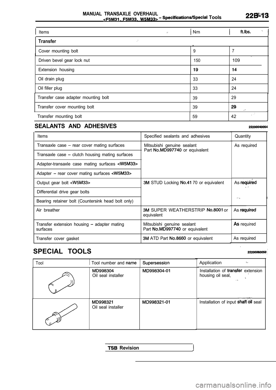
Items Nm
Transfer
Cover mounting bolt
,
97
Driven bevel gear lock nut
Extension housing150109
Oil drain plug 3324
Oil filler plug3324
Transfer case adapter mounting bolt
Transfer cover mounting bolt
39 29
39
Transfer mounting bolt
5942
SEALANTS AND ADHESIVES
Items
Transaxle case rear cover mating surfacesSpecified sealants and adhesives
Mitsubishi genuine sealant
Part
or equivalent
Transaxle case clutch housing mating surfaces
Adapter-transaxle case mating surfaces
Adapter rear cover mating surfaces
Output gear bolt STUD Locking 70 or equivalent
Differential drive gear bolts
Bearing retainer bolt (Countersink head bolt only)
Air breather
SUPER WEATHERSTRIP or
equivalent
Transfer extension housing
adapter mating
surfaces
Transfer cover gasket Mitsubishi genuine sealant
Part
or equivalent
ATD Part or equivalent
SPECIAL TOOLS
Tool Tool number and Application
Oil seal installer
Oil seal installer
Quantity
As required
As.
As
Asrequired
As required
Installation of
extension
housing oil seal,
Installation of input seal
Revision
Page 909 of 2103
MANUAL TRANSAXLE OVERHAUL
Transaxle
Lubricate all internalparts with oil during reassembly.
19 Nm19
54
58
Disassembly steps
Bearing retainer 51. Intermediate gear assembly
52. Input shaft assembly
53. Output shaft assembly
54. Differential gear assembly
55. Bearing outer race
56. Oil guide
57. Bearing outer race
58. Bearing outer race’ 59. Oil seal 60. Oil seal61. Clutch housing assembly
6 2 . M a g n e t
6 3 . M a g n e t h o l d e r
TSB Revision
Page 912 of 2103
MANUAL TRANSAXLE Transaxle
19N m1453
Lubricate all internalparts with engine oil
during reassembly.
.
Disassembly steps
Bearing retainer 54. Intermediate gear assembly
55. Input shaft assembly 56. Output shaft assembly
57. Differential gear assembly 58. Bearing outer race
59. Bearing outer race 60. Oil guide
61. Bearing outer race
62. Bearing outer race
63. Oil seal 64. Oil seal65. Magnet 6 6 . M a g n e t h o l d e r67. Clutch housing assembly
TSB Revision I
Page 915 of 2103
Disassembly steps
38. Clutch oil line bracket
39. Transaxle case40. Oil guide
41. Oil guide
42. Outer race
43. Spacer 44. Spacer
45. Stopper bracket
46. Oil seal
47. Reverse shift lever assembly
48. Reverse shift lever shoe .
49. Reverse idler gear
50. Reverse idler gear
51. Front output shaft assembly
52. Needle bearing
53. Front erential
TSB Revision
Page 916 of 2103
MANUAL TRANSAXLE OVERHAUL
Disassembly steps
54. Spring pin 55. Spring pin 56. Shift rail assembly 57. Bolt58. Bearing retainer
59. Intermediate gear assembly 60. Input shaft assembly61. Outer race62. Outer race
Oil 64. race’ 65. O i l s e a l
O i l ‘ s e a l 68. Magnet Magnet 70. Clutch housing assembly
TSB Revision
Page 917 of 2103
MANUAL TRANSAXLE OVERHAUL Transaxle
23
NUTS FOR INPUT
INTERMEDIATE GEAR
(1) Unstake nuts of the input shaft and
gear.
(2) the transaxle in reverse using control lever and
select lever.
(3) Install the special tool onto the input shaft.
(4) Screw a bolt
mm in.)] into the bolt
clutch housing and attach a spinner handle to special
(5) Remove the lock nut, while using the bolt as a spinner
handle stopper.
R A I L A S S E M B L Y
(1) Shift the speed fork to the speed.
(2) Shift the
speed fork to the speed.
TSB Revision
(3)Remove the shift rail as shown in the
so as not to hit the interlock plate and
Page 921 of 2103
MANUAL TRANSAXLE OVERHAUL
Transaxle
IDLER GEAR SHAFT BOLT
INSTALLATION
(1)Center the shaft with a Phillips screwdriver [shaft diameter
8 mm in.)] or the like.
(2) Tighten the reverse idler gear shaft bolt to th e specified
torque.
LOCK NUTS FOR INPUT SHAFT
INTERMEDIATE GEAR INSTALLATION,
(1) Install the special tool onto the input shaft.
(2) Screw a bolt [IO mm in.)] into the hole around clutch
housing and attach a handle to the
(3)Shift the transaxle in reverse using control lever and
(4) the lock nut to the specified torque, using
the bolt attached in the above step as a spinner ha ndle
stopper.
(5) Stake the lock nut.
PIN FOR SHIFT FORK
INSTALLATION
TSB Revision
Page 936 of 2103

M A N U A L T R A N S A X L E ’ O V E R H A U L
Shaft , ,
2 0 1 0 5 1
II
Synchronizer ringGear2110009
201044
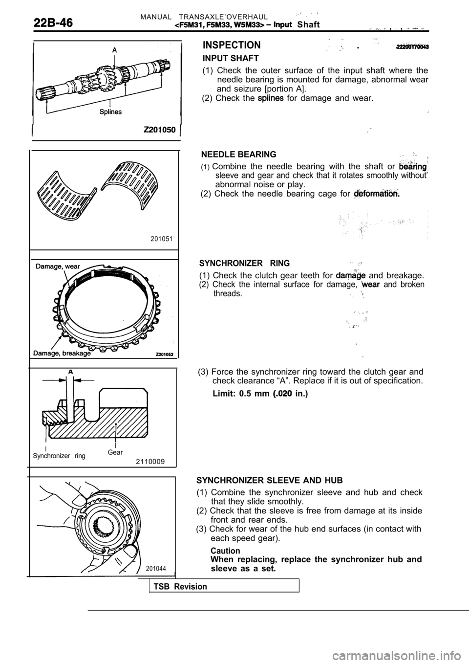
INSPECTION
INPUT SHAFT
. . .
(1) Check the outer surface of the input shaft wher
e the
needle bearing is mounted for damage, abnormal wear
and seizure [portion A].
(2) Check the
for damage and wear.
NEEDLE BEARING
(1) Combine the needle bearing with the shaft or
sleeve and gear and check that it rotates smoothly without’
abnormal noise or play.
(2) Check the needle bearing cage for
SYNCHRONIZER RING
(1) Check the clutch gear teeth for and breakage.
(2) Check the internal surface for damage, and broken
threads.
(3) Force the synchronizer ring toward the clutch g ear and
check clearance “A”. Replace if it is out of specif ication.
Limit: 0.5 mm
in.)
SYNCHRONIZER SLEEVE AND HUB (1) Combine the synchronizer sleeve and hub and che ck
that they slide smoothly.
(2) Check that the sleeve is free from damage at it s inside
front and rear ends.
(3) Check for wear of the hub end surfaces (in cont act with
each speed gear).
Caution
When replacing, replace the synchronizer hub and sleeve as a set.
TSB Revision