1990 MITSUBISHI SPYDER change wheel
[x] Cancel search: change wheelPage 531 of 2103
ENGINE (TURBO)
AND
ENGINE>
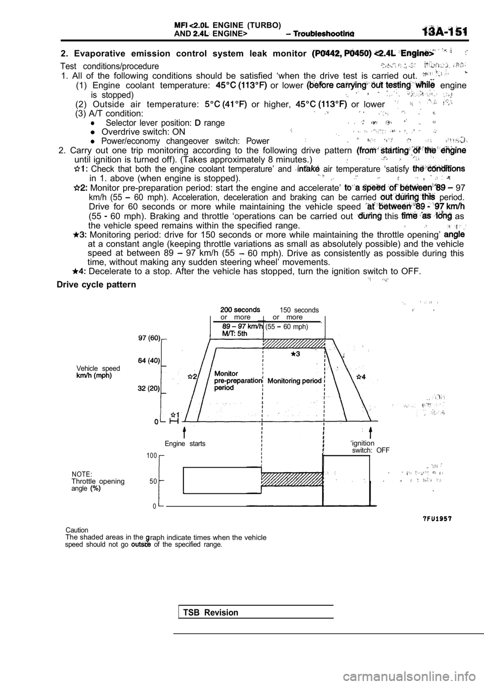
2. Evaporative emission control system leak monitor
Test conditions/procedure , . .
1. All of the following conditions should be satisfied ‘when the drive test is carried out.
(1) Engine coolant temperature: or lower engine
is stopped) ,
(2) Outside air temperature: or higher, or lower
(3) A/T condition: .
lSelector lever position: range .
l Overdrive switch: ON
l Power/economy changeover switch: Power
2. Carry out one trip monitoring according to the f ollowing drive pattern
until ignition is turned off). (Takes approximately 8 minutes.)
Check that both the engine coolant temperature’ an d air temperature ‘satisfy
in 1. above (when engine is stopped). ,
Monitor pre-preparation period: start the engine and accelerate’ 97
km/h (55 60 mph). Acceleration, deceleration and braking ca n be carried period.
Drive for 60 seconds or more while maintaining the vehicle speed
(55 60 mph). Braking and throttle ‘operations can be carried out this as
the vehicle speed remains within the specified rang e.
Monitoring period: drive for 150 seconds or more w hile maintaining the throttle opening’
at a constant angle (keeping throttle variations as small as absolutely possible) and the vehicle
speed at between 89
97 km/h (55 60 mph). Drive as consistently as possible during this
time, without making any sudden steering wheel’ mov ements.
Decelerate to a stop. After the vehicle has stopped, turn the ignition switch to OFF.
Drive cycle pattern
150 seconds
Vehicle speed
NOTE:Throttle openingangle
or more __ or more
.
(55 60 mph)
Engine starts
1 0 0
50
0
I
‘ignitionswitch: OFF
,
CautionThe shaded areas in theraph indicate times when the vehiclespeed should not go of the specified range.
TSB Revision
Page 532 of 2103
ENGINE (TURBO)
AND
ENGINE> Troubleshooting
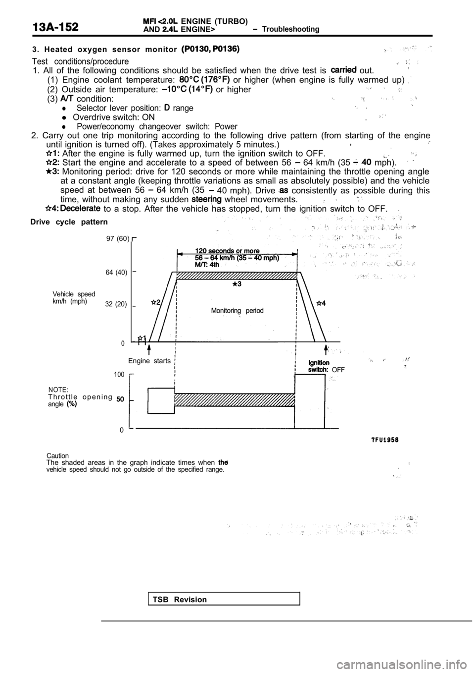
3 . H e a t e d o x y g e n s e n s o r m o n i t o r
Test conditions/procedure
1. All of the following conditions should be satisf ied when the drive test is out.
(1) Engine coolant temperature: or higher (when engine is fully warmed up)
(2) Outside air temperature: or higher
(3) condition:
lSelector lever position: range
l Overdrive switch: ON.
lPower/economy changeover switch: Power
2. Carry out one trip monitoring according to the f ollowing drive pattern (from starting of the engine
until ignition is turned off). (Takes approximately 5 minutes.),
After the engine is fully warmed up, turn the igni
tion switch to OFF.
Start the engine and accelerate to a speed of betw een 56 64 km/h (35 mph).
Monitoring period: drive for 120 seconds or more w hile maintaining the throttle opening angle
at a constant angle (keeping throttle variations as small as absolutely possible) and the vehicle
speed at between 56
64 km/h (35 40 mph). Drive consistently as possible during this
time, without making any sudden
wheel movements.
to a stop. After the vehicle has stopped, turn the ignition switch to OFF.
Drive cycle pattern
97 (60)
64 (40)
Vehicle speed
km/h (mph) 32 (20)
0
Monitoring period
Monitoring period
TSB Revision
Engine starts
I. .
OFF100
NOTE:T h r o t t l e o p e n i n g angle
0
CautionThe shaded areas in the graph indicate times when vehicle speed should not go outside of the specifie
d range.
Page 533 of 2103
ENGINE (TURBO)
AND
ENGINE> Troubleshooting
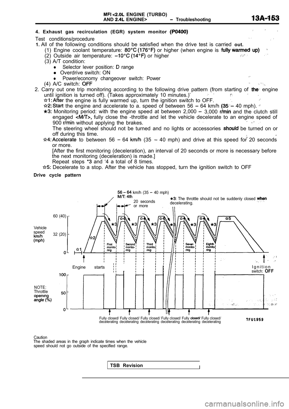
4. Exhaust gas recirculation (EGR) system monitor
Test conditions/procedure
1. All of the following conditions should be satisfied when the drive test is carried out.
(1) Engine coolant temperature:
or higher (when engine is
(2) Outside air temperature: or higher
(3) A/T condition:
lSelector lever position: range
l Overdrive switch: ON
lPower/economy changeover switch: Power
(4) A/C switch:
2. Carry out one trip monitoring according to the f ollowing drive pattern (from starting of engine
until ignition is turned off). (Takes approximately 10 minutes.)’
the engine is fully warmed up, turn the ignition s witch to OFF.
the engine and accelerate to a. speed of between 5 6 64 km/h 40 mph).
Monitoring period: with the engine speed at between 2,000 3,000 and the clutch still
engaged
fully close the -throttle and let the vehicle dece lerate to an engine speed of
900
without applying the brakes.
The steering wheel should not be turned and no ligh ts or accessories be turned on or
off during this time.
to between 56 64 (35 40 mph) and drive at this speed for 20 seconds
or more.
[After the first monitoring (deceleration), an inte rval of 20 seconds or more is necessary before
the next monitoring (deceleration) is made.]
Repeat steps
and ‘4 a total of 8 times.
Decelerate to a stop. After the vehicle has stoppe d, turn the ignition switch to OFF
Drive cycle pattern
60 (40)
Vehicle
speed
32 (20)
NOTE:Throttle
km/h (35 40 mph)
20 seconds
The throttle should not be suddenly closed
or more decelerating.
Engine starts I g n i t i o nswitch:OFF
Fully closed/ Fully closed/ Fully closed/ Fully clo
sed/ Fully Fully closed/
decelerating decelerating decelerating decelerating decelerating decelerating
TSB RevisionI
Caution
The shaded areas in the graph indicate times when t he vehicle
speed should not go outside of the specified range.
Page 535 of 2103
ENGINE (TURBO)
AND
ENGINE> Troubleshooting .
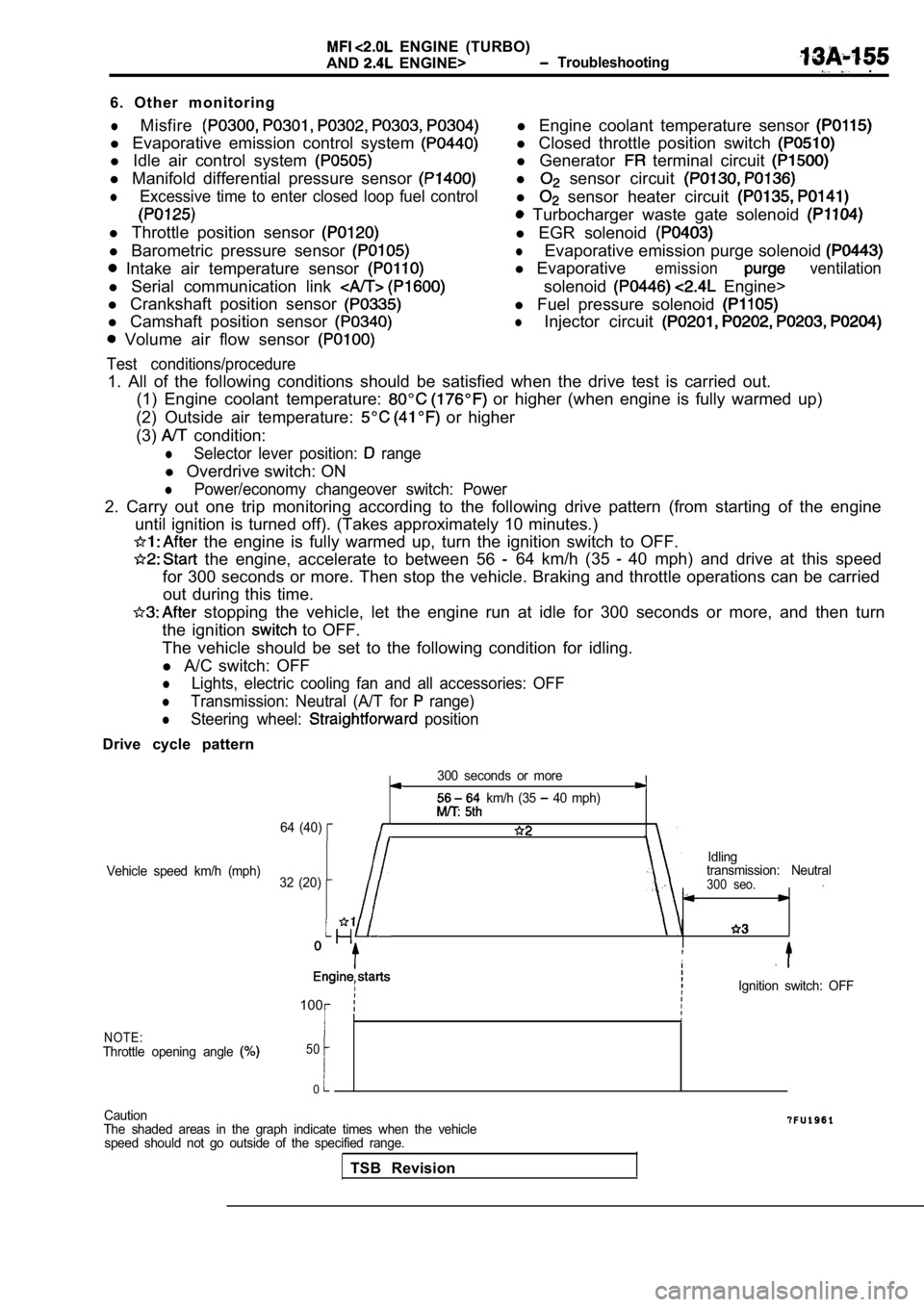
6. Other monitoring
lMisfire
l Evaporative emission control system
l Idle air control system
l Manifold differential pressure sensor
lExcessive time to enter closed loop fuel control
l Throttle position sensor
l Barometric pressure sensor
Intake air temperature sensor
l Serial communication link
l Crankshaft position sensor
l Camshaft position sensor
Volume air flow sensor
Test conditions/procedure
l Engine coolant temperature sensor
l Closed throttle position switch
l Generator terminal circuit
l sensor circuit
l sensor heater circuit
Turbocharger waste gate solenoid
l EGR solenoid
lEvaporative emission purge solenoid
l Evaporativeemissionventilation
solenoid Engine>
l Fuel pressure solenoid
lInjector circuit
1. All of the following conditions should be satisf ied when the drive test is carried out.
(1) Engine coolant temperature:
or higher (when engine is fully warmed up)
(2) Outside air temperature:
or higher
(3)
condition:
lSelector lever position: range
l Overdrive switch: ON
lPower/economy changeover switch: Power
2. Carry out one trip monitoring according to the f ollowing drive pattern (from starting of the engine
until ignition is turned off). (Takes approximately 10 minutes.)
the engine is fully warmed up, turn the ignition s witch to OFF.
the engine, accelerate to between 56 64 km/h (35 40 mph) and drive at this speed
for 300 seconds or more. Then stop the vehicle. Bra king and throttle operations can be carried
out during this time.
stopping the vehicle, let the engine run at idle f or 300 seconds or more, and then turn
the ignition
to OFF.
The vehicle should be set to the following conditio n for idling.
l A/C switch: OFF
lLights, electric cooling fan and all accessories: O FF
lTransmission: Neutral (A/T for range)
lSteering wheel: position
Drive cycle pattern
300 seconds or more
km/h (35 40 mph)
64 (40)
Idling
Vehicle speed km/h (mph) transmission: Neutral
32 (20)
300 seo.
,
Ignition switch: OFF
100
NOTE:Throttle opening angle 50
0
Caution
The shaded areas in the graph indicate times when t he vehicle
speed should not go outside of the specified range.
TSB Revision
Page 580 of 2103
ENGINE (TURBO)
AND Troubleshooting
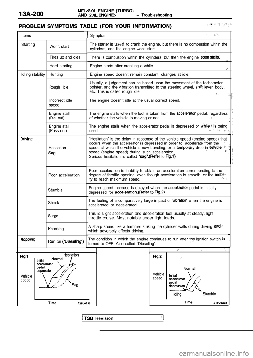
Items
Starting
Idling stabilityWon’t start Fires up and dies
Hard starting
Hunting
Rough idle
Incorrect idle
speed
Engine stall
(Die out)
Engine stall
(Pass out)
Hesitation
Poor acceleration
Stumble
Shock
Surge
Knocking
Run on
Symptom
The starter is usedto crank the engine, but there is no combustion wit hin the
cylinders, and the engine won’t start.
There is combustion within the cylinders, but then the engine
Engine starts after cranking a while.
Engine speed doesn’t remain constant; changes at id le.
Usually, a judgement can be based upon the movement of the tachometer
pointer, and the vibration transmitted to the steer ing wheel,
lever, body,
etc. This is called rough idle.
The engine doesn’t idle at the usual correct speed.
The engine stalls when the foot is taken from the
pedal, regardless
of whether the vehicle is moving or not.
The engine stalls when the accelerator pedal is dep ressed or being
used.
“Hesitation” is the delay in response of the vehicle speed (engine speed) that
occurs when the accelerator is depressed in order t o, accelerate from the
speed at which the vehicle is now traveling, or a drop in
speed (engine speed) during such acceleration.
Serious hesitation is called to
Poor acceleration is inability to obtain an acceleration corresponding to the
degree of throttle opening, even though acceleratio n is smooth, or the
to reach maximum speed.
Engine speed increase is delayed when the pedal is initially
depressed for
to
The feeling of a comparatively large impact or when the engine is
accelerated or decelerated.
This is slight acceleration and deceleration feel u sually at steady, light
throttle cruise. Most notable under light loads.
A sharp sound like a hammer striking the cylinder w alls during driving
which adversely affects driving.
The condition in which the engine continues to run after
ignition switch
turned to OFF. Also called “Dieseling”.
Vehicle
speedHesitation
Hesitation
Time
Vehicle
speed
Idling Stumble
Revision
Page 1656 of 2103
BASIC BRAKE SYSTEM On-vehicle Service
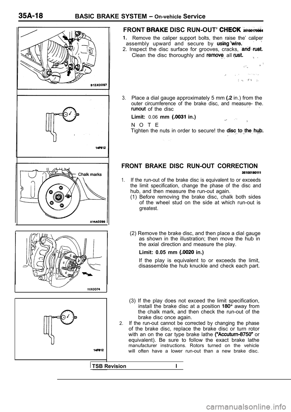
FRONT DISC RUN-OUT’
Remove the caliper support bolts, then raise the’ c aliper
assembly upward and secure by
2. Inspect the disc surface for grooves, cracks,
Clean the disc thoroughly and all
,
3.Place a dial gauge approximately 5 mm in.) from the
outer circumference of the brake disc, and measure- the.
of the disc
Limit:0.06mm in.)
N O T E
Tighten the nuts in order to secure! the
FRONT BRAKE DISC RUN-OUT CORRECTION
1.If the run-out of the brake disc is equivalent to o r exceeds
the limit specification, change the phase of the di sc and
hub, and then measure the run-out again.
(1) Before removing the brake disc, chalk both side s
of the wheel stud on the side at which run-out is
greatest.
(2) Remove the brake disc, and then place a dial ga uge
as shown in the illustration; then move the hub in
the axial direction and measure the play.
Limit: 0.05 mm
in.)
If the play is equivalent to or exceeds the limit,
disassemble the hub knuckle and check each part.
2.
(3) If the play does not exceed the limit specifica tion,
install the brake disc at a position
away from
the chalk mark, and then check the run-out of the
brake disc once again.
If the run-out cannot be corrected by changing the phase
of the brake disc, replace the brake disc or turn rotor
with an on the car type brake lathe
or
equivalent). Be sure to follow the exact brake lath e
manufacturer instructions. Rotors turned on the veh icle
will often have a lower run-out than a new brake di sc.
TSB RevisionI
Page 1716 of 2103
ABS On-vehicle Service
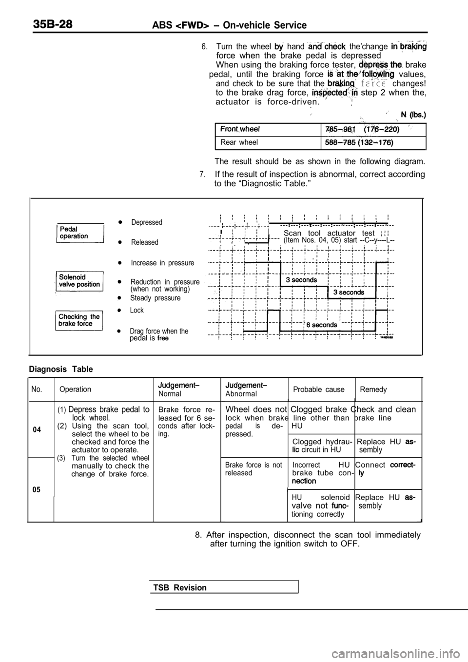
6.Turn the wheel hand the’change
force when the brake pedal is depressed
When using the braking force tester,
brake
pedal, until the braking force
values,
and check to be sure that the farce changes!
to the brake drag force, step 2 when the,
actuator is force-driven.
Rear wheel
The result should be as shown in the following diag ram.
7.If the result of inspection is abnormal, correct according
to the “Diagnostic Table.”
Depressed
Released
Increase in pressure
Reduction in pressure
(when not working)
Steady pressure
Lock
Drag force when the
pedal is
- - - ! - - - ; - - - t - - - ! - - - : - - - ~ - - - ; - - - : - - - i - - - ~ - -
I
Scan tool actuator test ,
, , (Item Nos. 04, 05) start --C--y----L--
, ,
Diagnosis Table
No.
04
Operation
(1)Depress brake pedal to
lock wheel.
(2) Using the scan tool,
select the wheel to be
checked and force the
actuator to operate.
(3)Turn the selected wheel
manually to check the
change of brake force.
05
Normal
Brake force re-
leased for 6 se-
conds after lock-
ing.
AbnormalProbable cause Remedy
Wheel does not Clogged brake Check and clean
lock when brake line other than brake line
pedalisde- HU
pressed.Clogged hydrau- Replace HU
circuit in HUsembly
Brake force is not IncorrectHU Connect
releasedbrake tube con-
HUsolenoid Replace HU
valve not sembly
tioning correctly
8. After inspection, disconnect the scan tool immed iately
after turning the ignition switch to OFF.
TSB Revision
Page 1753 of 2103
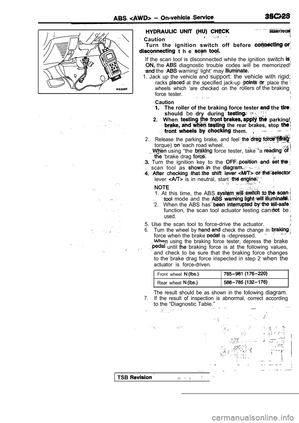
Caution,
Turn the ignition switch off before
t h e
If the scan tool is disconnected while the ignition
switch
the diagnostic trouble codes will be memorized!
the warning’ light’ may
1. Jack up the vehicle and support: the vehicle with rigid;
racks at the specified jack-up place the
wheels which ‘are checked on. .therollers of the braking
force tester.
Caution
The roller of the braking force tester the
shouldbedry during
2. When parking!
the rear brakes, stop
them.,
2.Release the parking brake, and feel
torque) ‘each road wheel. .
using “the force tester, take “a
‘brake drag
Turn the ignition key to the
scan tool as the
lever is in neutral, start
1. At this time, the ABS
‘2.
mode and the
When the ABS has’
function, the scan tool actuator testing canbe
used.
5. Use the scan tool to force-drive the actuator.
6.Turn the wheel by check the change in
force when the brake is -depressed.
using the braking force tester, depress the brake
until braking force is at the following values,
and check to be sure that the braking force changes
to the brake drag force inspected in step 2 when the
actuator is force-driven.
Front wheel
Rear wheel
The result should be as shown in the following diagram.
7.If the result of inspection is abnormal, correct ac cording
to the “Diagnostic Table.”__ .
,
__
TSB