1990 MITSUBISHI SPYDER timing belt
[x] Cancel search: timing beltPage 3 of 2103
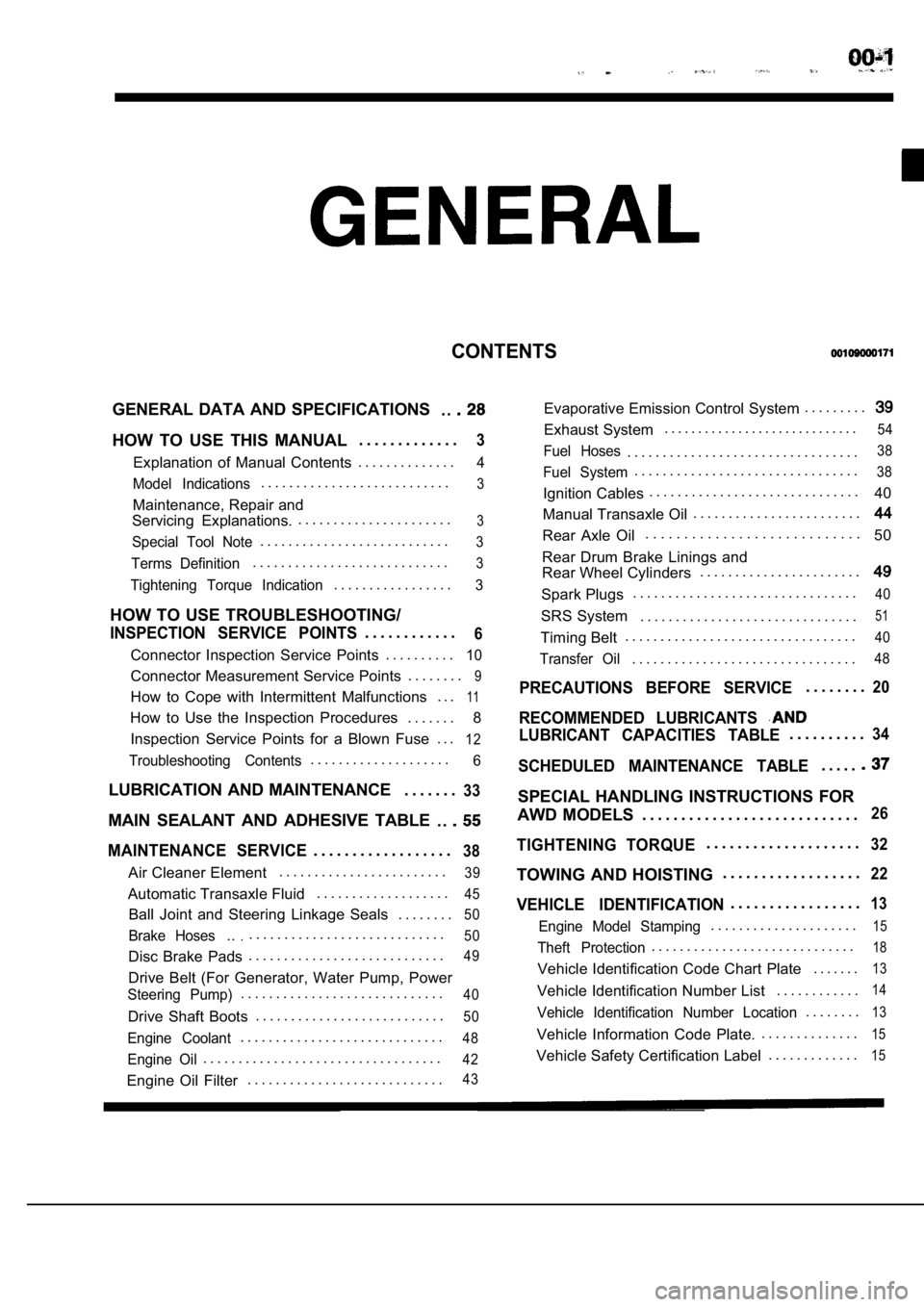
CONTENTS
GENERAL DATA AND SPECIFICATIONS. .
HOW TO USE THIS MANUAL. . . . . . . . . . . . .3
Explanation of Manual Contents. . . . . . . . . . . . . .4
Model Indications
. . . . . . . . . . . . . . . . . . . . . . . . . . .3
Maintenance, Repair and
Servicing Explanations. . . . . . . . . . . . . . . . . . . . . . .
3
Special Tool Note. . . . . . . . . . . . . . . . . . . . . . . . . . .3
Terms Definition. . . . . . . . . . . . . . . . . . . . . . . . . . . .3
Tightening Torque Indication. . . . . . . . . . . . . . . . .3
HOW TO USE TROUBLESHOOTING/
INSPECTION SERVICE POINTS. . . . . . . . . . . .6
Connector Inspection Service Points
. . . . . . . . . .10
Connector Measurement Service Points . . . . . . . .9
How to Cope with Intermittent Malfunctions . . .11
How to Use the Inspection Procedures
. . . . . . .
8
Inspection Service Points for a Blown Fuse . . .
12
Troubleshooting Contents. . . . . . . . . . . . . . . . . . . .6
LUBRICATION AND MAINTENANCE . . . . . . .33
MAIN SEALANT AND ADHESIVE TABLE
. .
MAINTENANCE SERVICE. . . . . . . . . . . . . . . . . .38
Air Cleaner Element. . . . . . . . . . . . . . . . . . . . . . . .39
Automatic Transaxle Fluid
. . . . . . . . . . . . . . . . . . .45
Ball Joint and Steering Linkage Seals
. . . . . . . .50
Brake Hoses.... . . . . . . . . . . . . . . . . . . . . . . . . . . .50
Disc Brake Pads. . . . . . . . . . . . . . . . . . . . . . . . . . . .49
Drive Belt (For Generator, Water Pump, Power
Steering Pump). . . . . . . . . . . . . . . . . . . . . . . . . . . . .40
Drive Shaft Boots
. . . . . . . . . . . . . . . . . . . . . . . . . . .50
Engine Coolant. . . . . . . . . . . . . . . . . . . . . . . . . . . . .48
Engine Oil. . . . . . . . . . . . . . . . . . . . . . . . . . . . . . . . . .42
Engine Oil Filter. . . . . . . . . . . . . . . . . . . . . . . . . . . .43
Evaporative Emission Control System . . . . . . . . .
Exhaust System. . . . . . . . . . . . . . . . . . . . . . . . . . . . .54
Fuel Hoses. . . . . . . . . . . . . . . . . . . . . . . . . . . . . . . . .38
Fuel System. . . . . . . . . . . . . . . . . . . . . . . . . . . . . . . .38
Ignition Cables. . . . . . . . . . . . . . . . . . . . . . . . . . . . . .
40
Manual Transaxle Oil . . . . . . . . . . . . . . . . . . . . . . . .
Rear Axle Oil. . . . . . . . . . . . . . . . . . . . . . . . . . . .
50
Rear Drum Brake Linings and
Rear Wheel Cylinders . . . . . . . . . . . . . . . . . . . . . . .
Spark Plugs. . . . . . . . . . . . . . . . . . . . . . . . . . . . . . . .40
SRS System . . . . . . . . . . . . . . . . . . . . . . . . . . . . . . .51
Timing Belt. . . . . . . . . . . . . . . . . . . . . . . . . . . . . . . . .40
Transfer Oil. . . . . . . . . . . . . . . . . . . . . . . . . . . . . . . .48
PRECAUTIONS BEFORE SERVICE. . . . . . . .20
RECOMMENDED LUBRICANTS
LUBRICANT CAPACITIES TABLE. . . . . . . . . .34
SCHEDULED MAINTENANCE TABLE. . . . .
SPECIAL HANDLING INSTRUCTIONS FOR
AWD MODELS . . . . . . . . . . . . . . . . . . . . . . . . . . . .
26
TIGHTENING TORQUE. . . . . . . . . . . . . . . . . . . .32
TOWING AND HOISTING . . . . . . . . . . . . . . . . . .22
VEHICLE IDENTIFICATION. . . . . . . . . . . . . . . . .13
Engine Model Stamping. . . . . . . . . . . . . . . . . . . . .15
Theft Protection. . . . . . . . . . . . . . . . . . . . . . . . . . . . .18
Vehicle Identification Code Chart Plate
. . . . . . .13
Vehicle Identification Number List. . . . . . . . . . . .14
Vehicle Identification Number Location. . . . . . . .13
Vehicle Information Code Plate.. . . . . . . . . . . . . .15
Vehicle Safety Certification Label
. . . . . . . . . . . . .15
Page 42 of 2103

GENERAL Maintenance
Incorrect Correct
5. SPARK PLUGS
1.Spark plugs must spark properly to assure proper engine
performance and reduce exhaust emission
Therefore, they should be periodically with new
ones.
2. The new plugs should be checked gap.
Spark plug gap:, . .
Engine (Turbo)>’
mm
Engine (Non-turbo)> ,
1.22-1.35 mm
in.)
Engine> .
in.)
3. Install the spark plug and tighten to the
Tightening torque:
Engine (Turbo) and Engine>
25 Nm (18
E n g i n e ( N o n - t u r b o ) >
28 Nm (20
6. IGNITION CABLES (Replace)
The ignition cables should. be replaced periodicall y with new
ones. After replacing, make sure that the ignition cables are
routed properly and fully seated.
NOTE
When disconnecting an ignition cable; be sure to ho ld the
cable boot. If the cable is disconnected by pulling on the
cable alone, an open circuit might result.
7. TIMING BELT (Replace)
00100220027
Replace the belt with a new one periodically to ass ure proper
engine performance.
For disassembly and assembly procedures; Refer to GROUP
Timing Belt.
Refer to GROUP
Timing Belt.
Refer to GROUP 11
Timing Belt.
8. DRIVE BELT (For Generator, Water Pump, Power Steering Pump) (Check condition)
Check the tension of the drive belt. Check the driv e belt
for evidence of cuts and cracks, and replace it if defective.
TSB Revision
Page 61 of 2103
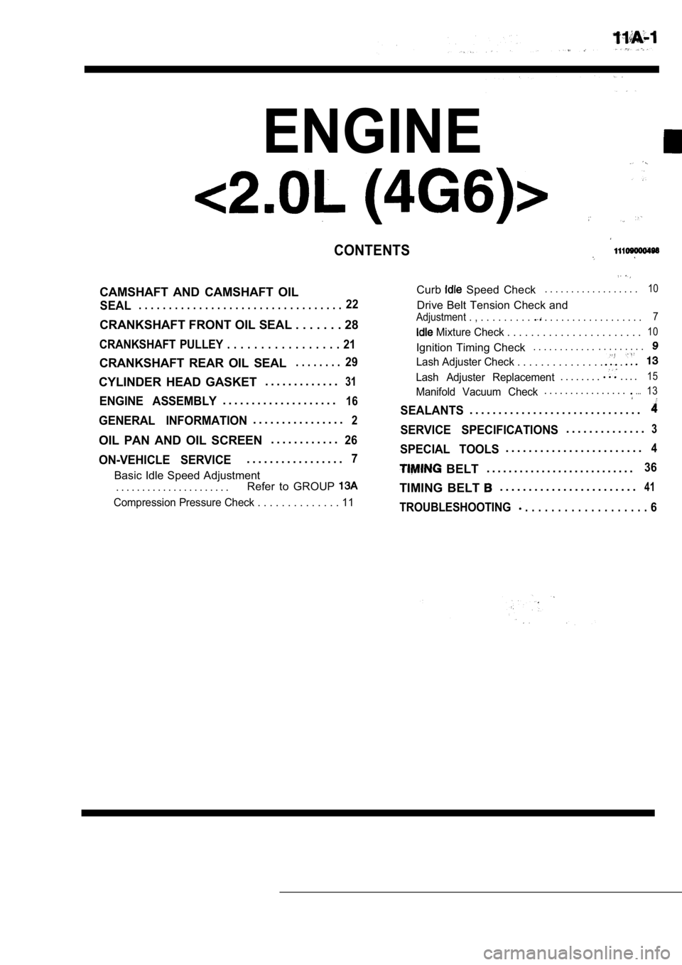
ENGINE
CONTENTS
CAMSHAFT AND CAMSHAFT OIL
SEAL. . . . . . . . . . . . . . . . . . . . . . . . . . . . . . . . . .22
CRANKSHAFT FRONT OIL SEAL . . . . . . . 28
CRANKSHAFT PULLEY . . . . . . . . . . . . . . . . . 21
CRANKSHAFT REAR OIL SEAL. . . . . . . .29
Curb Speed Check. . . . . . . . . . . . . . . . . .10
Drive Belt Tension Check and
Adjustment . , . . . . . . . . . . . . . . . . . . . . . . . . . . . 7
Mixture Check . . . . . . . . . . . . . . . . . .
. . . . .10
Ignition Timing Check. . . . . . . . . . . .. . . . . . . . .
Lash Adjuster Check . . . . . . . . . . . . . . . .
CYLINDER HEAD GASKET . . . . . . . . . . . . .31
ENGINE ASSEMBLY. . . . . . . . . . . . . . . . . . . .16
GENERAL INFORMATION. . . . . . . . . . . . . . . .2
OIL PAN AND OIL SCREEN . . . . . . . . . . . .26
ON-VEHICLE SERVICE. . . . . . . . . . . . . . . . .7
Basic Idle Speed Adjustment
. . . . . . . . . . . . . . . . . . . . . . Refer to GROUP
Lash Adjuster Replacement. . . . . . . .. . . .15
Manifold Vacuum Check. . . . . . . . . . . . . . . ....13
SEALANTS. . . . . . . . . . . . . . . . . . . . . . . . . . . . . .
SERVICE SPECIFICATIONS. . . . . . . . . . . . . .3
SPECIAL TOOLS. . . . . . . . . . . . . . . . . . . . . . . .4
BELT. . . . . . . . . . . . . . . . . . . . . . . . . . .36
TIMING BELT . . . . . . . . . . . . . . . . . . . . . . . .41
Compression Pressure Check . . . . . . . . . . . .
. . 11TROUBLESHOOTING . . . . . . . . . . . . . . . . . . . 6
Page 63 of 2103
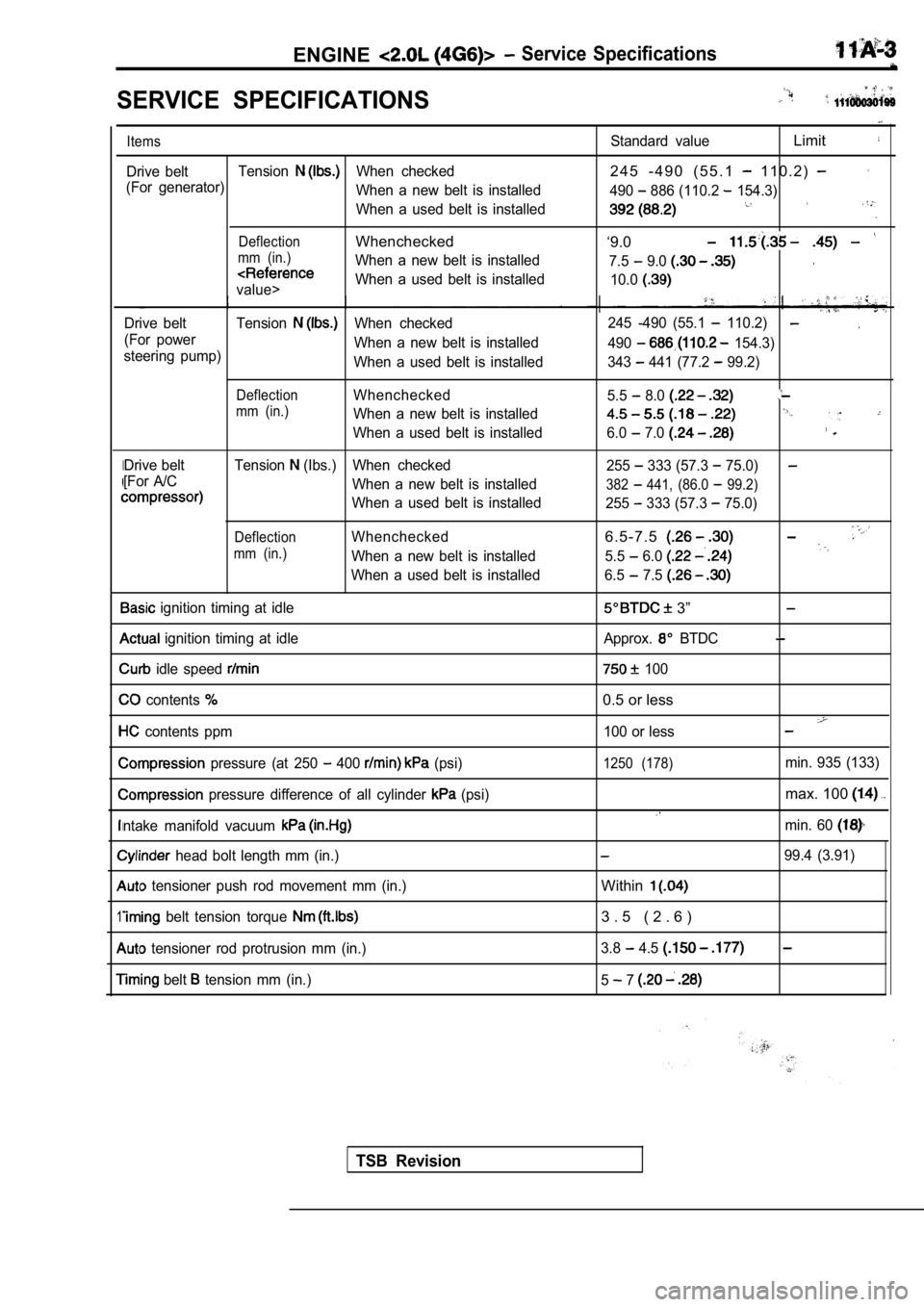
ENGINE Service Specifications
SERVICE SPECIFICATIONS
I
1
Items
Drive beltTensionWhen checked
(For generator) When a new belt is installed
When a used belt is installed
DeflectionWhenchecked
mm (in.)When a new belt is installed
value>When a used belt is installed
Drive belt Tension
When checked
(For power When a new belt is installed
steering pump) When a used belt is installed
DeflectionWhenchecked
mm (in.)When a new belt is installed
When a used belt is installed
Drive belt Tension
(Ibs.) When checked
[For A/C When a new belt is installed
When a used belt is installed
DeflectionWhenchecked
mm (in.)When a new belt is installed
When a used belt is installed
ignition timing at idle
ignition timing at idle
idle speed
contents
contents ppm
pressure (at 250 400 (psi)
pressure difference of all cylinder (psi)
ntake manifold vacuum
head bolt length mm (in.)
tensioner push rod movement mm (in.)
belt tension torque
tensioner rod protrusion mm (in.)
belt tension mm (in.)
Standard valueLimit
2 4 5 - 4 9 0 ( 5 5 . 1 1 1 0 . 2 )
490 886 (110.2 154.3)
‘9.0
7.5 9.0
10.0
.245 -490 (55.1 110.2)
490 154.3)
343
441 (77.2 99.2)
5.5
8.0
6.0 7.0
255 333 (57.3 75.0)
382 441, (86.0 99.2)
255 333 (57.3 75.0)
6 . 5 - 7 . 5
5.5 6.0
6.5 7.5
3”
Approx. BTDC
100
0.5 or less
100 or less
1250 (178)min. 935 (133)
max. 100
min. 60
99.4 (3.91)
Within
3 . 5 ( 2 . 6 )
3.8 4.5
5 7
TSB Revision
Page 69 of 2103
ENGINE On-vehicle
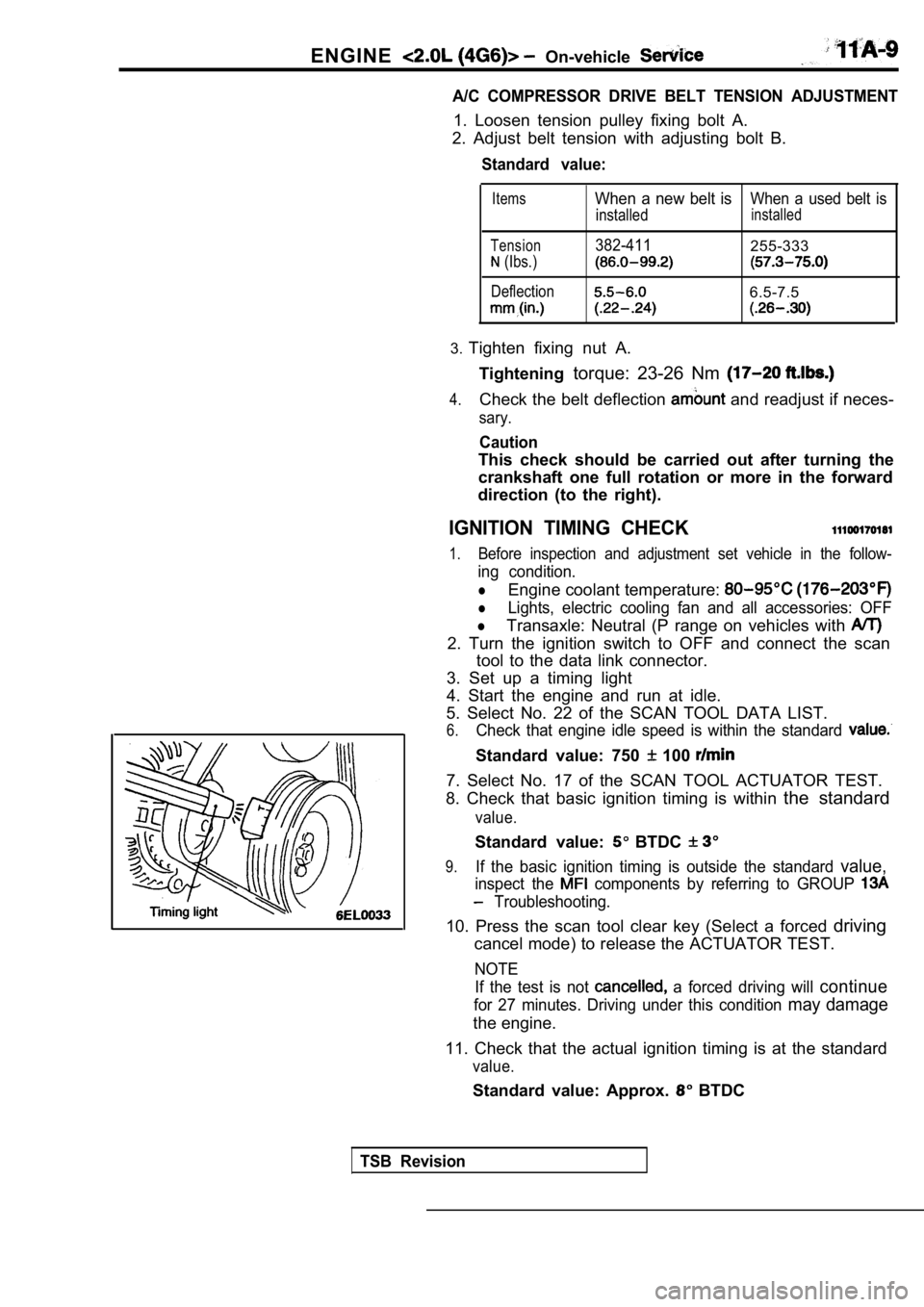
A/C COMPRESSOR DRIVE BELT TENSION ADJUSTMENT
1. Loosen tension pulley fixing bolt A.
2. Adjust belt tension with adjusting bolt B.
Standard value:
Items
Tension
(Ibs.)
Deflection
When a new belt isWhen a used belt is
installedinstalled
382-411255-333
6.5-7.5
3. Tighten fixing nut A.
Tightening torque: 23-26 Nm
4.Check the belt deflection and readjust if neces-
sary.
Caution
This check should be carried out after turning the
crankshaft one full rotation or more in the forward
direction (to the right).
IGNITION TIMING CHECK
1.Before inspection and adjustment set vehicle in the follow-
ing condition.
lEngine coolant temperature:
lLights, electric cooling fan and all accessories: OFF
lTransaxle: Neutral (P range on vehicles with
2. Turn the ignition switch to OFF and connect the scan
tool to the data link connector.
3. Set up a timing light
4. Start the engine and run at idle.
5. Select No. 22 of the SCAN TOOL DATA LIST.
6.Check that engine idle speed is within the standard
Standard value: 750 100
7. Select No. 17 of the SCAN TOOL ACTUATOR TEST.
8. Check that basic ignition timing is within the standard
value.
Standard value: BTDC
9.If the basic ignition timing is outside the standar d value,
inspect the components by referring to GROUP
Troubleshooting.
10. Press the scan tool clear key (Select a forced driving
cancel mode) to release the ACTUATOR TEST.
NOTE
If the test is not
a forced driving will continue
for 27 minutes. Driving under this condition may damage
the engine.
11. Check that the actual ignition timing is at the standard
value.
Standard value: Approx. BTDC
TSB Revision
Page 74 of 2103
ENGINE On-vehicle Service
Timing belt side
.
2.Start the engine and perform gentle racing* several times
(less than times.)
If the abnormal noise stops by racing, the air is b led
from the high pressure chamber of the lash adjusters
and the function of the lash adjusters is normalized.
After raising the engine speed from idling to 3000
gradually (in 30 seconds), drop the
ally (in 30 seconds) to idling.
NOTE
lIf the vehicle is parked on a slope for the oil
in the lash adjusters will be decreased ‘andairmay
enter the high pressure chamber when the
is started.
lAfter the vehicle is parked for long, air may enter
the high pressure chamber because the, oil in the
oil passage will be gone and, it will take a time b efore
the oil is supplied to the lash adjusters.
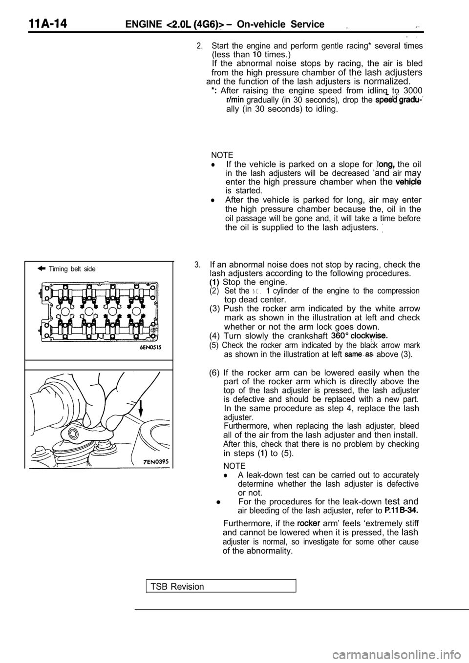
3.If an abnormal noise does not stop by racing, check the
lash adjusters according to the following procedure s.
Stop the engine.
(2)Set the NG. cylinder of the engine to the compression
top dead center.
(3) Push the rocker arm indicated by the white arro w
mark as shown in the illustration at left and check
whether or not the arm lock goes down.
(4) Turn slowly the crankshaft
(5) Check the rocker arm indicated by the black arr ow mark
as shown in the illustration at left above (3).
(6) If the rocker arm can be lowered easily when th e
part of the rocker arm which is directly above the
top of the lash adjuster is pressed, the lash adjus ter
is defective and should be replaced with a new part .
In the same procedure as step 4, replace the lash
adjuster.
Furthermore, when replacing the lash adjuster, bleed
all of the air from the lash adjuster and then install.
After this, check that there is no problem by check ing
in steps to (5).
NOTE
lA leak-down test can be carried out to accurately
determine whether the lash adjuster is defective
or not.
l For the procedures for the leak-down test and
air bleeding of the lash adjuster, refer to
Furthermore, if the arm’ feels ‘extremely stiff
and cannot be lowered when it is pressed, the lash
adjuster is normal, so investigate for some other c ause
of the abnormality.
TSB Revision
Page 82 of 2103
ENGINECamshaft and Oil Seal
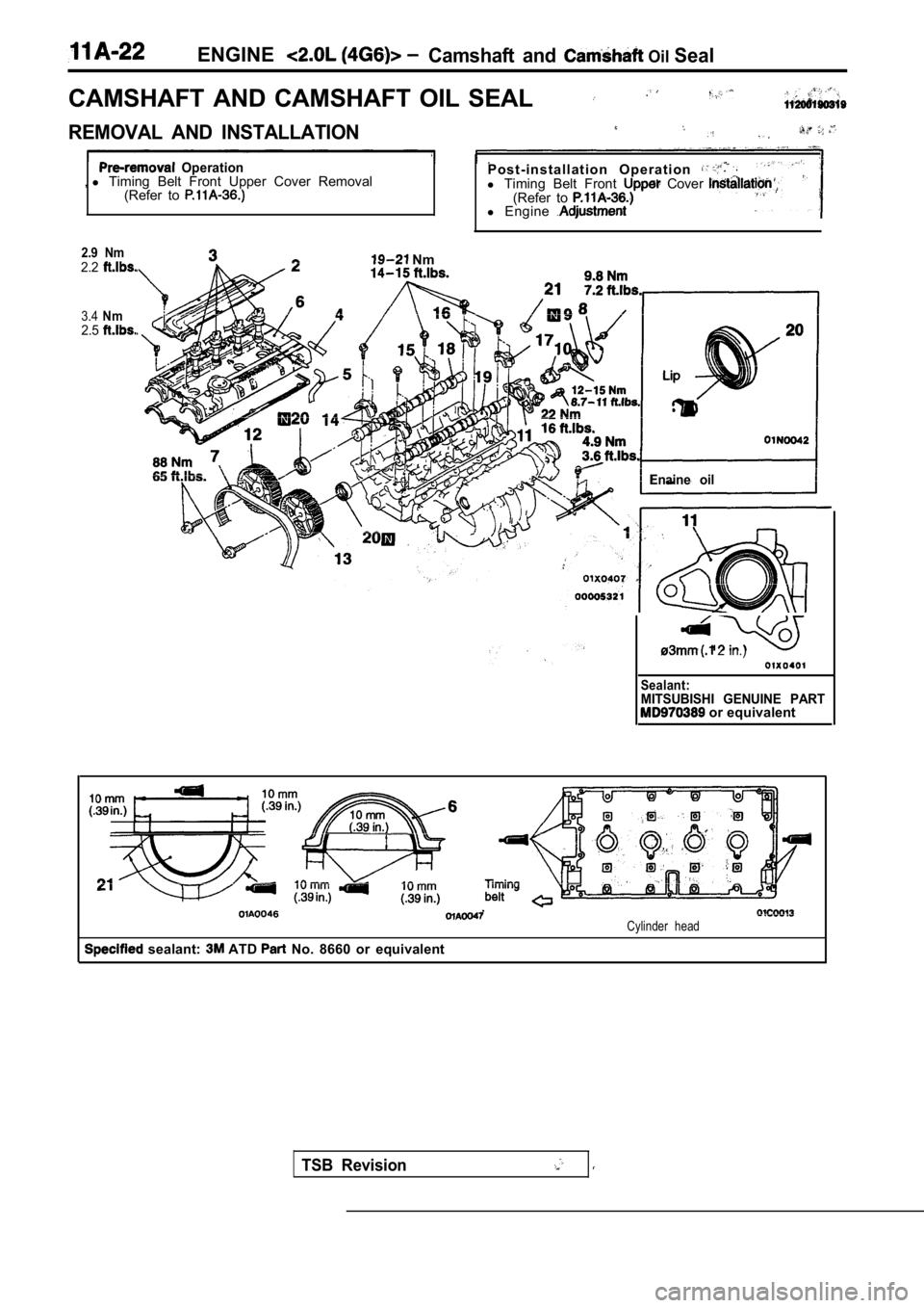
CAMSHAFT AND CAMSHAFT OIL SEAL
REMOVAL AND INSTALLATION
Operation,l Timing Belt Front Upper Cover Removal
(Refer to P o s t - i n s t a l l a t i o n O p e r a t i o n l Timing Belt Front Cover (Refer to l Engine
2.9 Nm2.2
3.4Nm2.5
Nm
Enaine oil
TSB Revision
2 in.)
Sealant:MITSUBISHI GENUINE PART or equivalent
Cylinder head
sealant: ATD No. 8660 or equivalent
Page 83 of 2103
ENGINECamshaft and Camshaft ‘Oil -Seal
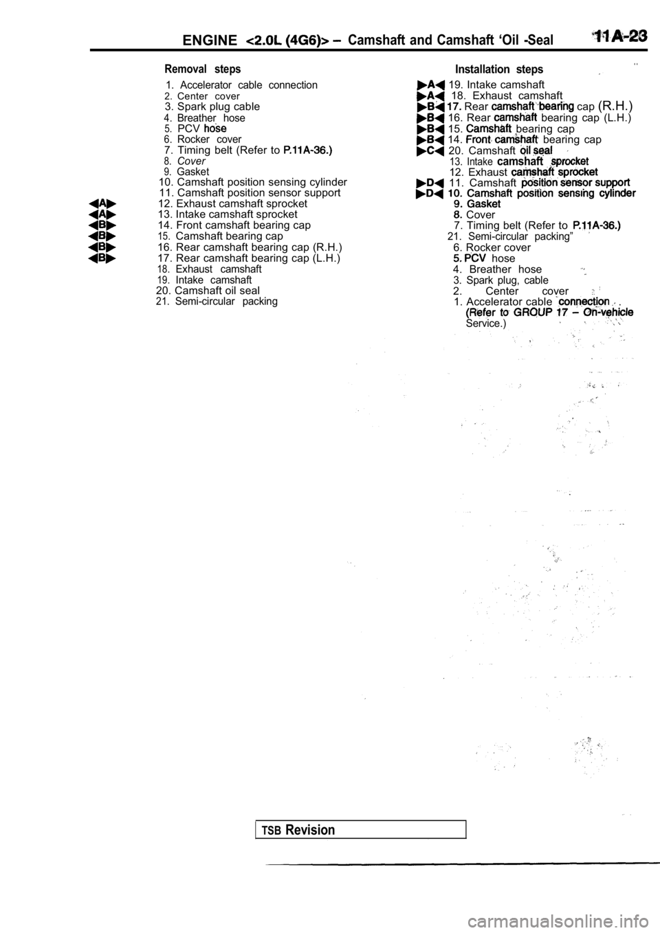
Removal steps
1. Accelerator cable connection2.Center cover
3. Spark plug cable
4.Breather hose5.PCV6.Rocker cover7. Timing belt (Refer to 8.Cover9.Gasket10. Camshaft position sensing cylinder 11. Camshaft position sensor support
12. Exhaust camshaft sprocket
13. Intake camshaft sprocket
14. Front camshaft bearing cap
15.Camshaft bearing cap
16. Rear camshaft bearing cap (R.H.)
17. Rear camshaft bearing cap (L.H.)
18.Exhaust camshaft19.Intake camshaft20. Camshaft oil seal21.Semi-circular packing
Installation steps. .
19. Intake camshaft 18. Exhaust camshaft Rear cap (R.H.)
16. Rear bearing cap (L.H.)
15. bearing cap 14. bearing cap
20. Camshaft 13. Intake camshaft12. Exhaust 11. Camshaft
Cover
7. Timing belt (Refer to
21. Semi-circular packing”
6. Rocker cover hose
4. Breather hose
3. Spark plug, cable2. Center cover 1. Accelerator cable .
Service.)
TSBRevision