Page 88 of 2103
ENGINECrankshaft Front Oil’
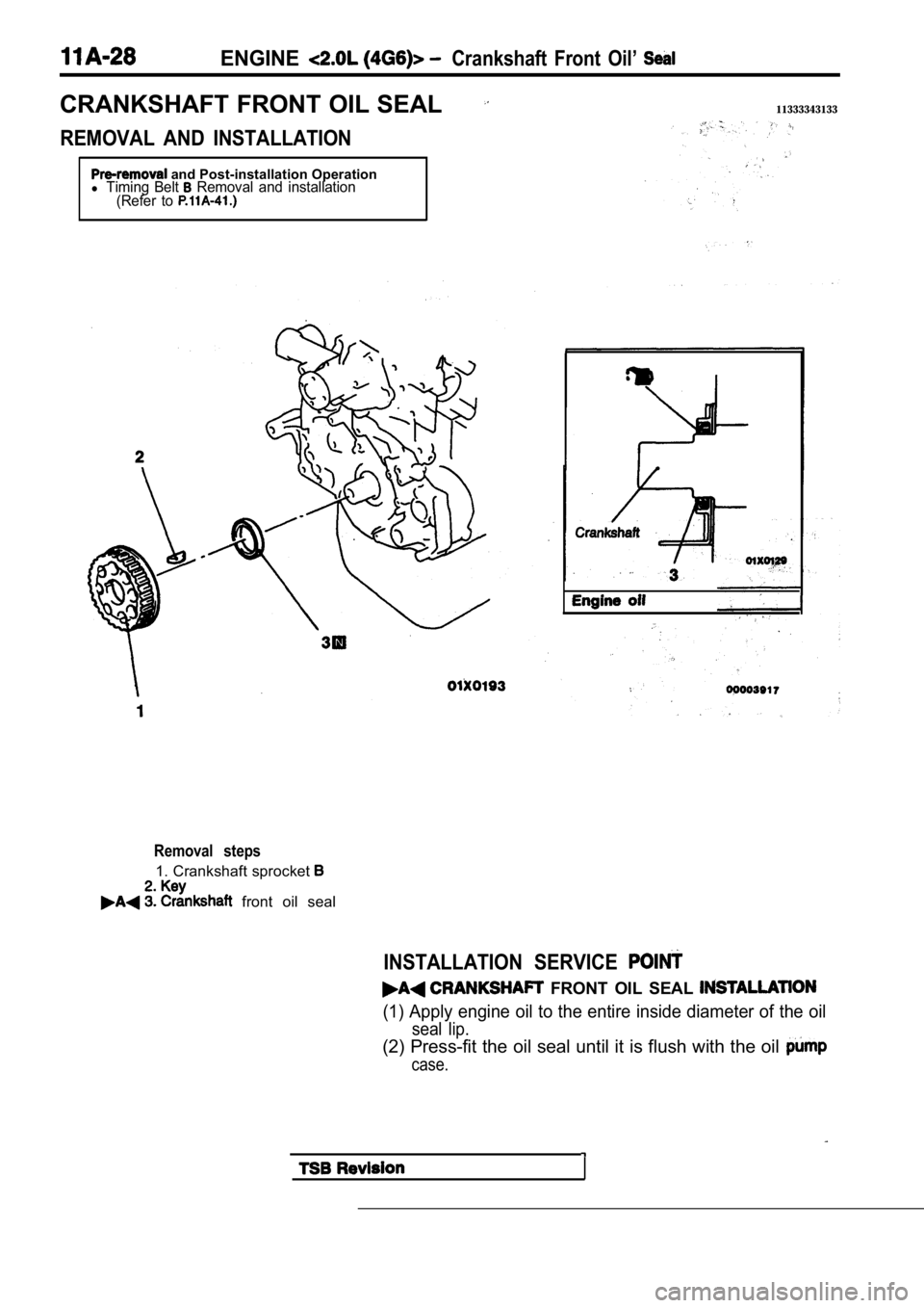
CRANKSHAFT FRONT OIL SEAL11333343133
REMOVAL AND INSTALLATION
and Post-installation Operationl Timing Belt Removal and installation
(Refer to
Removal steps
1. Crankshaft sprocket
front oil seal
INSTALLATION SERVICE
FRONT OIL SEAL
(1) Apply engine oil to the entire inside diameter of the oil
seal lip.
(2) Press-fit the oil seal until it is flush with the oil
case.
Page 92 of 2103
ENGINE Head Gasket’.
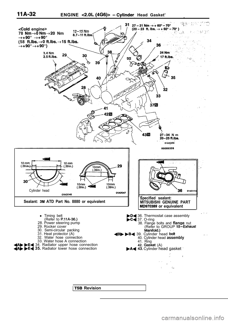
engine>
78
Nm
(58
N m
Cylinder head
Sealant: ATD Part No. 8880 or equivalent
Revision
Specified sealant: MITSUBISHI GENUINE PART
or equivalent
36. Thermostat case assembly 37. O-ring38. Flange bolts and flangenut(Refer to GROUP
39. Cylinder head 40. Cylinder head assembly41. Ring42. (A) Cylinder head gasket
l Timing belt(Refer to 28. Power steering pump
29. Rocker cover
30. Semi-circular packing31. Heat protector (A)32. Water hose connection33. Water hose A connection 34. Radiator upper hose connection 35. Radiator lower hose connection
Page 96 of 2103
E N G I N E Timing Belt
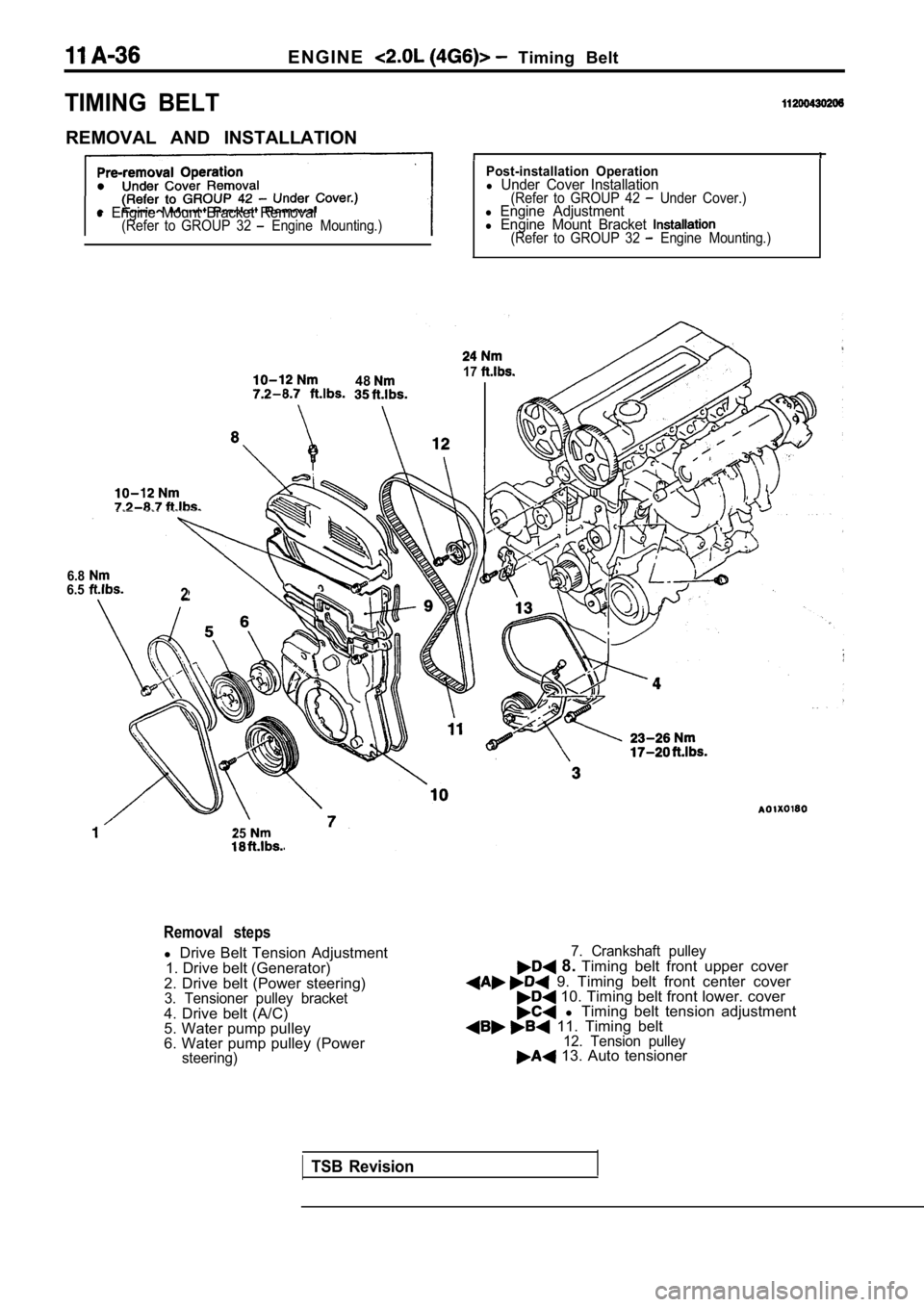
TIMING BELT
REMOVAL AND INSTALLATION
l Engine Mount Bracket Removal(Refer to GROUP 32 Engine Mounting.)
Post-installation Operationl Under Cover Installation(Refer to GROUP 42 Under Cover.)l Engine Adjustmentl Engine Mount Bracket (Refer to GROUP 32 Engine Mounting.)
4817
6.86.52
25
Removal steps
l Drive Belt Tension Adjustment
1. Drive belt (Generator)
2. Drive belt (Power steering)
3. Tensioner pulley bracket4. Drive belt (A/C)
5. Water pump pulley
6. Water pump pulley (Power
steering)
7. Crankshaft pulley 8. Timing belt front upper cover 9. Timing belt front center cover 10. Timing belt front lower. cover l Timing belt tension adjustment 11. Timing belt12. Tension pulley 13. Auto tensioner
TSB Revision
Page 97 of 2103
ENGINE Timing
(22-44
A
tensioner
marks Cylinder headI surface
I I I
REMOVAL SERVICE POINTS
BELT FRONT CENTER COVER
Remove the stud bolt of the engine support bracket, and
remove the timing belt front center cover.
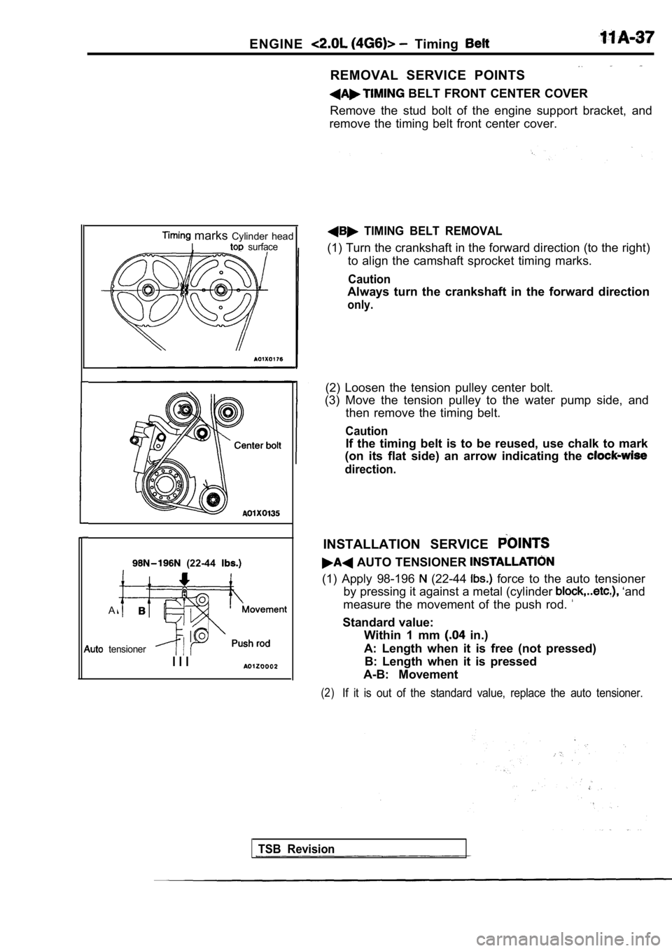
TIMING BELT REMOVAL
(1) Turn the crankshaft in the forward direction (t o the right)
to align the camshaft sprocket timing marks.
Caution
Always turn the crankshaft in the forward direction
only.
(2) Loosen the tension pulley center bolt.
(3) Move the tension pulley to the water pump side, and
then remove the timing belt.
Caution
If the timing belt is to be reused, use chalk to ma rk
(on its flat side) an arrow indicating the
direction.
INSTALLATION SERVICE
AUTO TENSIONER
(1) Apply 98-196 (22-44 force to the auto tensioner
by pressing it against a metal (cylinder
‘and
measure the movement of the push rod.
Standard value: Within 1 mm
in.)
A: Length when it is free (not pressed) B: Length when it is pressed
A-B: Movement
(2)If it is out of the standard value, replace the aut o tensioner.
TSB Revision
Page 98 of 2103
ENGINE Timing Belt
,Set pin
I
Timing marksCylinder had
Itop surface
Crankshaft
sprocket
60 mm
60 mm
(2.36 in.)
(2.36 in.)
or more
or more in.) in.)
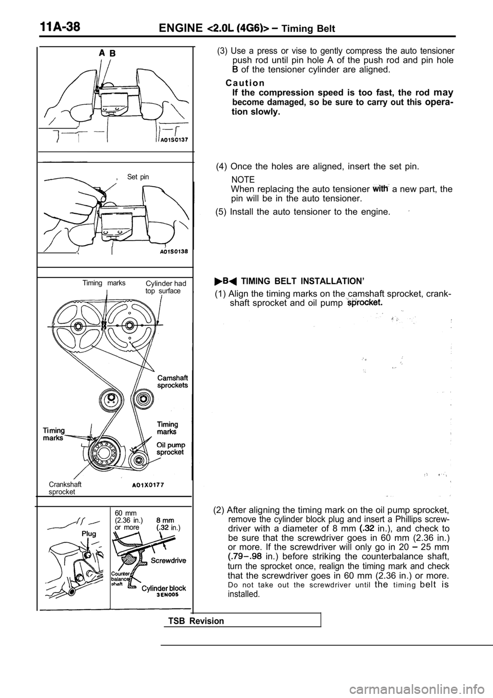
(3) Use a press or vise to gently compress the auto tensioner
push rod until pin hole A of the push rod and pin hole
of the tensioner cylinder are aligned.
C a u t i o n If the compression speed is too fast, the rod may
become damaged, so be sure to carry out this opera-
tion slowly.
(4) Once the holes are aligned, insert the set pin.
NOTE
When replacing the auto tensioner a new part, the
pin will be in the auto tensioner.
(5) Install the auto tensioner to the engine.
TIMING BELT INSTALLATION’
(1) Align the timing marks on the camshaft sprocket , crank-
shaft sprocket and oil pump
(2) After aligning the timing mark on the oil pump sprocket,
remove the cylinder block plug and insert a Phillips screw-
driver with a diameter of 8 mm in.), and check to
be sure that the screwdriver goes in 60 mm (2.36 in .)
or more. If the screwdriver will only go in 20
25 mm
in.) before striking the counterbalance shaft,
turn the sprocket once, realign the timing mark and check
that the screwdriver goes in 60 mm (2.36 in.) or mo re.
Do not take out the screwdriver until thet i m i n g b e l t i s
installed.
TSB Revision
Page 99 of 2103
E N G I N E
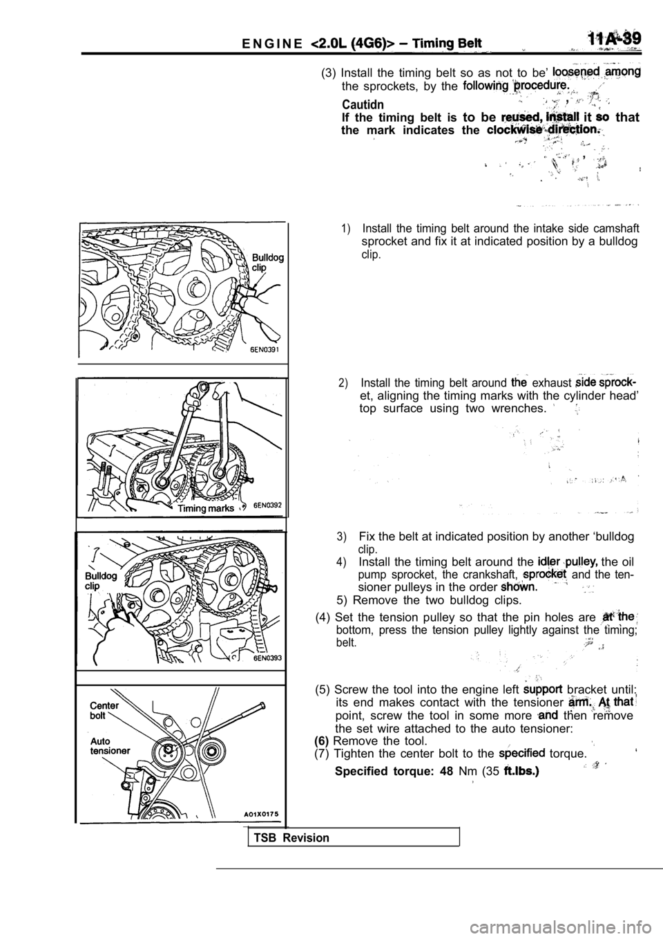
(3) Install the timing belt so as not to be’
the sprockets, by the
Cautidn ,
If the timing belt is to be it that
the mark indicates the
,
1)Install the timing belt around the intake side cams haft
sprocket and fix it at indicated position by a bulldog
clip.
2)Install the timing belt around exhaust
et, aligning the timing marks with the cylinder hea d’
top surface using two wrenches.
3)Fix the belt at indicated position by another ‘bull dog
clip.
4)
Install the timing belt around the the oil
pump sprocket, the crankshaft, and the ten-
sioner pulleys in the order
5) Remove the two bulldog clips.
(4) Set the tension pulley so that the pin holes ar e
bottom, press the tension pulley lightly against the timing;
belt.
(5) Screw the tool into the engine left bracket until:
its end makes contact with the tensioner
point, screw the tool in some more then remove
the set wire attached to the auto tensioner:
(6) Remove the tool.
(7) Tighten the center bolt to the
torque.
Specified torque: 48 Nm (35
TSB Revision
Page 100 of 2103
E N G I N E Belt
Auto tensioner
TIMING BELT TENSION ADJUSTMENT
(1) After turning the crankshaft of a revolution in the
counterclockwise direction, turn it in the clockwise direction
. until the timing marks are aligned.
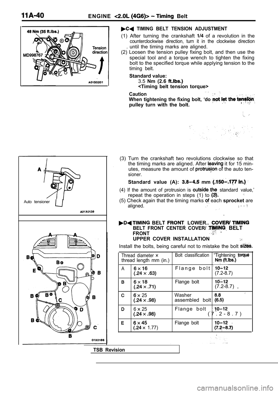
(2) Loosen the tension pulley fixing bolt, and then use the
special tool and a torque wrench to tighten the fix ing
bolt to the specified torque while applying tension to the
timing belt.
Standard value:
3.5 Nm (2.6
Caution
When tightening the fixing bolt, ‘do
pulley turn with the bolt.,
(3) Turn the crankshaft two revolutions clockwise s o that
the timing marks are aligned. After
it for 15 min-
utes, measure the amount of
of the auto ten-
sioner.
Standard value (A): mm
(4) If the amount of protrusion is standard value,’
repeat the operation in steps (1) to
(5) Check again that the timing marks each sprocket are
aligned. . .
.
BELT LOWER..
BELT FRONT CENTER COVER/ BELT
FRONT .
UPPER COVER INSTALLATION
Install the bolts, being careful not to mistake the bolt
Thread diameter Bolt classification“Tightening
thread length mm (in.)
AF l a n g e b o l t
(7.2-8.7)
Flange bolt(7.2-8.7) ,
25Washer
assembled bolt
6 25F l a n g e b o l t
( 7 . 2 - 8 . 7 )
Flange bolt
1.77)
TSB Revision
Page 101 of 2103
ENGINE Timing
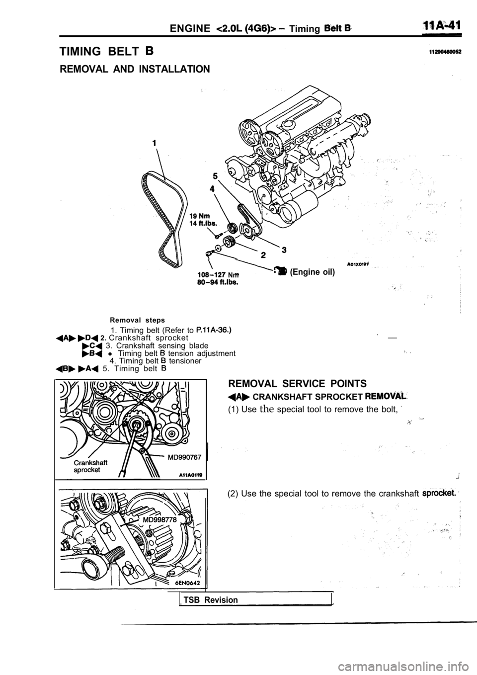
TIMING BELT
REMOVAL AND INSTALLATION
(Engine oil) Nm
Removal steps1. Timing belt (Refer to
2. Crankshaft sprocket 3. Crankshaft sensing blade l Timing belt tension adjustment
4. Timing belt tensioner 5. Timing belt
__
REMOVAL SERVICE POINTS
CRANKSHAFT SPROCKET
(1) Use thespecial tool to remove the bolt,
(2) Use the special tool to remove the crankshaft
TSB Revision