Page 50 of 2103

GENERAL Maintenance Service
,
Revision
Drain Plug
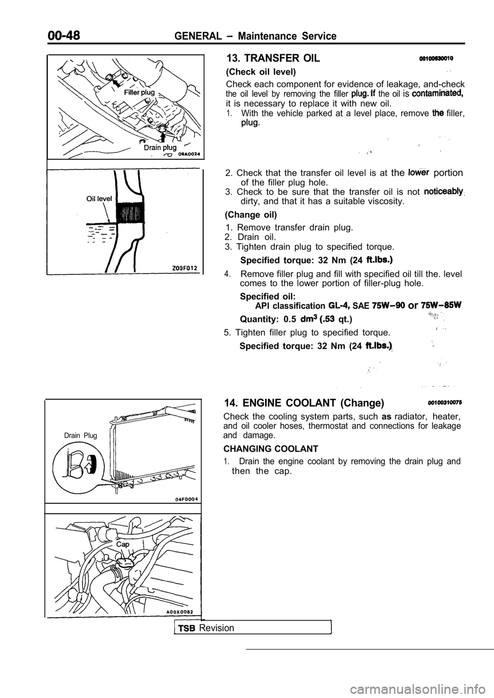
13. TRANSFER OIL
(Check oil level)
Check each component for evidence of leakage, and-check
the oil level by removing the filler the oil is
it is necessary to replace it with new oil.
1.With the vehicle parked at a level place, remove filler,
2. Check that the transfer oil level is at the portion
of the filler plug hole.
3. Check to be sure that the transfer oil is not
dirty, and that it has a suitable viscosity.
(Change oil) 1. Remove transfer drain plug.
2. Drain oil.
3. Tighten drain plug to specified torque.
Specified torque: 32 Nm (24
4.Remove filler plug and fill with specified oil till the. level
comes to the lower portion of filler-plug hole.
Specified oil:
API classification SAE or
Quantity: 0.5 qt.)
5. Tighten filler plug to specified torque.
Specified torque: 32 Nm (24
14. ENGINE COOLANT (Change)
Check the cooling system parts, such asradiator, heater,
and oil cooler hoses, thermostat and connections fo r leakage
and damage.
CHANGING COOLANT
1.Drain the engine coolant by removing the drain plug and
then the cap.
Page 51 of 2103

GENERAL Maintenance
a
Engine (Non-turbo)>
in plug
Engine>
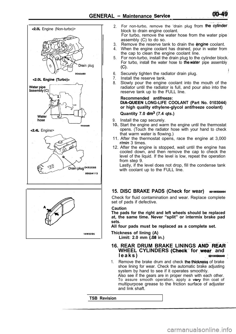
2.For non-turbo, remove the ‘drain plug from
block to drain engine coolant.
For turbo, remove the water hose from the water pip e
assembly (C) to do so.
3.
4.
5.Remove the reserve tank to drain the coolant.
When the engine coolant has drained, pour in water from
the cap to clean the engine coolant line.
For non-turbo, install the drain plug to the cylind er block.
For turbo, install the water hose to pipe assembly
6.
7.
8.
Securely tighten the radiator drain plug.
Install the reserve tank.
9.
Slowly pour the engine coolant into the mouth of th e
radiator until the radiator is full, and pour also into the
reserve tank up to the FULL line.
Recommended antifreeze:
LONG-LIFE COOLANT (Part No. 0103044)
or high quality ethylene-glycol antifreeze coolant)
Quantity 7.0
(7.4 qts.)
Install the cap securely.
Start the engine and warm the engine until the the rmostat
opens. (Touch the radiator hose with your hand to c heck
that warm water is flowing.)
11. After the thermostat opens, race the engine at 3,000
3 times.
12. After the engine is stopped, wait until the eng ine has
cooled down, and then remove the cap to check the
level of the liquid. If the level is low, repeat th e operation
from step 9.
Lastly, if the level does not drop, fill the conden se tank
with coolant up to the FULL line.
15. DISC BRAKE PADS (Check for wear)
Check for fluid contamination and wear. Replace com plete
set of pads if defective.
Caution
The pads for the right and left wheels should be re placed
at, the same time. Never “split” or intermix brake pad
sets.
All four pads must be replaced as a complete set.
Thickness of lining (A) Limit: 2.0 mm
in.)
16. REAR DRUM BRAKE LININGS
WHEEL CYLINDERS for and
l e a k s )
1.Remove the brake drum and check of brake
shoe lining for wear. Check the automatic brake adj usting
system by hand to see if it operates smoothly.
Also see if the gears are in proper mesh with each other.
To assure smooth operation, apply a thin coat of
multipurpose grease to the friction surface of adju ster
and link shaft.
TSB Revision
Page 76 of 2103

ENGINE Engine
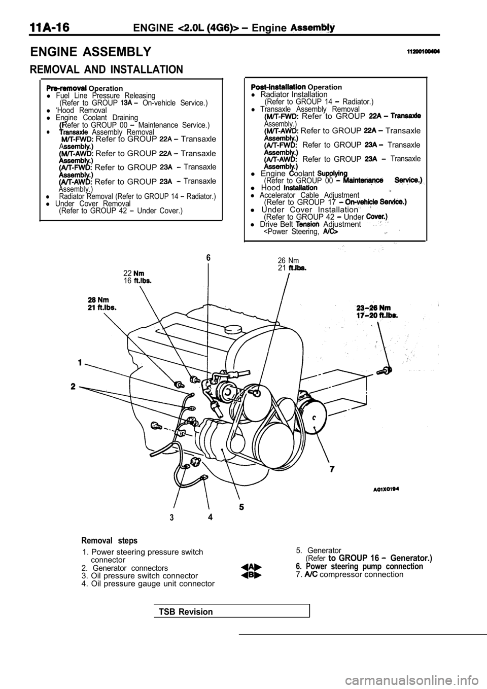
ENGINE ASSEMBLY
REMOVAL AND INSTALLATION
Operationl Fuel Line Pressure Releasing(Refer to GROUP On-vehicle Service.)l ‘Hood Removall Engine Coolant DrainingRefer to GROUP 00 Maintenance Service.)l Assembly Removal Refer to GROUP TransaxleA Refer to GROUP Transaxle
Refer to GROUP Transaxle
Refer to GROUP TransaxleAssembly.)lRadiator Removal (Refer to GROUP 14 Radiator.)l Under Cover Removal (Refer to GROUP 42 Under Cover.)
6
2216
Operationl Radiator Installation(Refer to GROUP 14 Radiator.)l Transaxle Assembly Removal Refer to GROUP Assembly.) Refer to GROUP Transaxle
Refer to GROUP Transaxle
Refer to GROUP
Transaxle
l Engineoolant(Refer to GROUP 00 l Hoodl Accelerator Cable Adjustment(Refer to GROUP 17 l Under Cover Installation(Refer to GROUP 42 Under l Drive Belt Adjustment
26 Nm21
34
Removal steps
1. Power steering pressure switchconnector
2. Generator connectors
3. Oil pressure switch connector
4. Oil pressure gauge unit connector
5. Generator(Referto GROUP 16 Generator.)
6. Power steering pump connection7. compressor connection
TSB Revision
Page 92 of 2103
ENGINE Head Gasket’.
engine>
78
Nm
(58
N m
Cylinder head
Sealant: ATD Part No. 8880 or equivalent
Revision
Specified sealant: MITSUBISHI GENUINE PART
or equivalent
36. Thermostat case assembly 37. O-ring38. Flange bolts and flangenut(Refer to GROUP
39. Cylinder head 40. Cylinder head assembly41. Ring42. (A) Cylinder head gasket
l Timing belt(Refer to 28. Power steering pump
29. Rocker cover
30. Semi-circular packing31. Heat protector (A)32. Water hose connection33. Water hose A connection 34. Radiator upper hose connection 35. Radiator lower hose connection
Page 93 of 2103
ENGINE Cylinder Head Gasket,
Intake sideFront of
engine
Exhaust side
REMOVAL SERVICE POINTS
UPPER HOSE/RADIATOR
HOSE
.Place mating marks on the radiator hose and the hos e clamp,
and then disconnect the radiator hose.
HEAD BOLT REMOVAL
Using the special tool, loosen the bolts in the ord er shown
in the illustration (in 2 or 3 stages), and then the
cylinder head assembly.
INSTALLATION SERVICE
CYLINDER HEAD GASKET INSTALLATION
(1) all oil and grease from the gasket mounting
(2) Install the gasket to the cylinder block with the identification
mark facing upwards.
HEAD BOLT INSTALLATION
(1) When installing the cylinder head-bolts, the le ngth below
the head of the bolts should be within the
If it is outside the limit, bolts.
(A): 99.4 mm (3.91 In.)
(2) Apply engine oil to the bolt thread and the was her..
TSB Revision
Page 95 of 2103
ENGINE Cylinder Head Gasket
i n . )
Mating marks
(2) Apply specified sealant to the thermostat case
in the places shown in the illustration.
Specified
MITSUBISHI GENUINE PART equiva-
lent
(3) Apply a small amount of water to the O-ring water
inlet pipe, and then press the thermostat case
into the water inlet pipe.
(4) Tighten the thermostat case assembly mounting b olts.
(5) Tighten the water inlet pipe bolts.
RADIATOR LOWER HOSE/RADIATOR UPPER HOSE CONNECTION
(1) Insert each hose as far as the projection of th e water
outlet fitting or water inlet fitting.
(2) Align the mating marks on the radiator hose and hose
clamp, and then connect the radiator hose.
HIGH-PRESSURE FUEL CONNECTION
When connecting the fuel hose to the fuel rail,
apply a small amount of clean engine oil to the hos e union
and then insert, being careful not to damage the
Caution
Do not let engine oil get into the fuel rail.
TSB Revision
Page 184 of 2103

ENGINE Engine
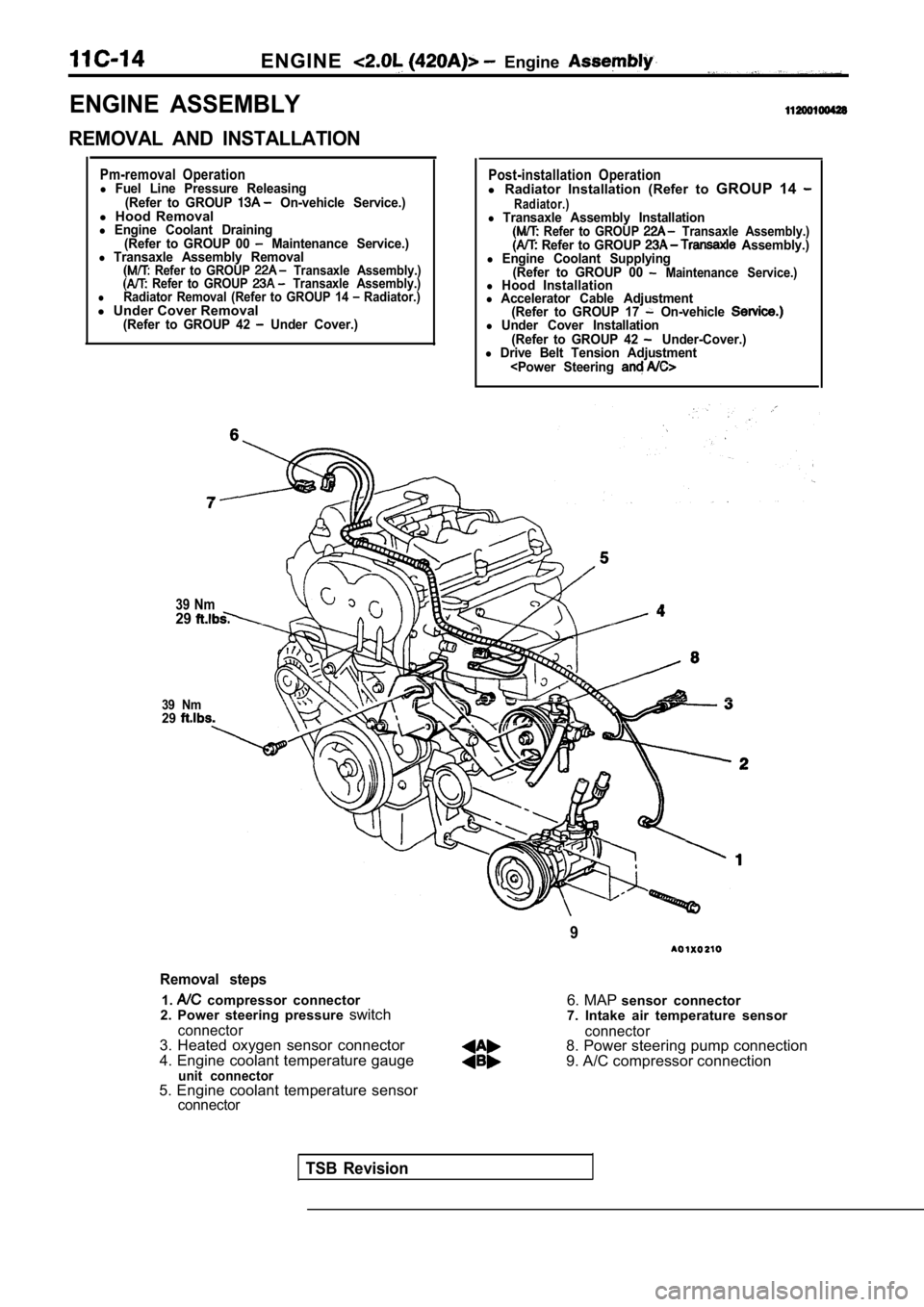
ENGINE ASSEMBLY
REMOVAL AND INSTALLATION
Pm-removal Operationl Fuel Line Pressure Releasing(Refer to GROUP On-vehicle Service.)l Hood Removall Engine Coolant Draining
(Refer to GROUP 00 Maintenance Service.)l Transaxle Assembly Removal Refer to GROUP Transaxle Assembly.) Refer to GROUP Transaxle Assembly.)lRadiator Removal (Refer to GROUP 14 Radiator.)l Under Cover Removal(Refer to GROUP 42 Under Cover.)
39 Nm29
39 Nm29
Post-installation Operationl Radiator Installation (Refer to GROUP 14 Radiator.)l Transaxle Assembly Installation Refer to GROUP Transaxle Assembly.) Refer to GROUP Assembly.)l Engine Coolant Supplying
(Refer to GROUP 00 Maintenance Service.)l Hood Installationl Accelerator Cable Adjustment(Refer to GROUP 17 On-vehicle l Under Cover Installation
(Refer to GROUP 42 Under-Cover.)l Drive Belt Tension Adjustment
9
Removal steps
1. compressor connector
2. Power steering pressure switch
connector3. Heated oxygen sensor connector
4. Engine coolant temperature gauge
unit connector
6. MAP sensor connector
7. Intake air temperature sensor
connector8. Power steering pump connection
9. A/C compressor connection
5. Engine coolant temperature sensor
connector
TSB Revision
Page 200 of 2103
ENGINE Cylinder Head
4.9 Nm
10
Engine oil
TSB Revision
2
15
8. Accelerator cable connection
9. Throttle position sensor connector
10. air motor connector11. Injector harness connector
12. Ignition coil connector
13. Camshaft position sensor connector
14. EGR solenoid valve connector
15. Heater hose connection
16. High-pressure fuel hose connection 17. Purge air hose connection
Brake booster. vacuum hoseconnection
19. Overflow tube connection
20. Radiator upper hose connection 21. Water hose
22. Intake manifold stay