1990 MITSUBISHI SPYDER air filter
[x] Cancel search: air filterPage 3 of 2103
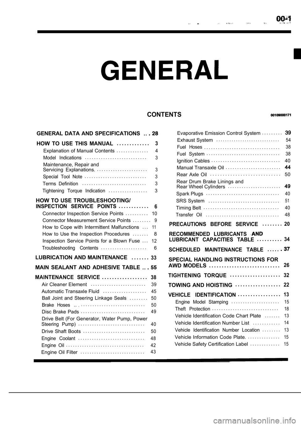
CONTENTS
GENERAL DATA AND SPECIFICATIONS. .
HOW TO USE THIS MANUAL. . . . . . . . . . . . .3
Explanation of Manual Contents. . . . . . . . . . . . . .4
Model Indications
. . . . . . . . . . . . . . . . . . . . . . . . . . .3
Maintenance, Repair and
Servicing Explanations. . . . . . . . . . . . . . . . . . . . . . .
3
Special Tool Note. . . . . . . . . . . . . . . . . . . . . . . . . . .3
Terms Definition. . . . . . . . . . . . . . . . . . . . . . . . . . . .3
Tightening Torque Indication. . . . . . . . . . . . . . . . .3
HOW TO USE TROUBLESHOOTING/
INSPECTION SERVICE POINTS. . . . . . . . . . . .6
Connector Inspection Service Points
. . . . . . . . . .10
Connector Measurement Service Points . . . . . . . .9
How to Cope with Intermittent Malfunctions . . .11
How to Use the Inspection Procedures
. . . . . . .
8
Inspection Service Points for a Blown Fuse . . .
12
Troubleshooting Contents. . . . . . . . . . . . . . . . . . . .6
LUBRICATION AND MAINTENANCE . . . . . . .33
MAIN SEALANT AND ADHESIVE TABLE
. .
MAINTENANCE SERVICE. . . . . . . . . . . . . . . . . .38
Air Cleaner Element. . . . . . . . . . . . . . . . . . . . . . . .39
Automatic Transaxle Fluid
. . . . . . . . . . . . . . . . . . .45
Ball Joint and Steering Linkage Seals
. . . . . . . .50
Brake Hoses.... . . . . . . . . . . . . . . . . . . . . . . . . . . .50
Disc Brake Pads. . . . . . . . . . . . . . . . . . . . . . . . . . . .49
Drive Belt (For Generator, Water Pump, Power
Steering Pump). . . . . . . . . . . . . . . . . . . . . . . . . . . . .40
Drive Shaft Boots
. . . . . . . . . . . . . . . . . . . . . . . . . . .50
Engine Coolant. . . . . . . . . . . . . . . . . . . . . . . . . . . . .48
Engine Oil. . . . . . . . . . . . . . . . . . . . . . . . . . . . . . . . . .42
Engine Oil Filter. . . . . . . . . . . . . . . . . . . . . . . . . . . .43
Evaporative Emission Control System . . . . . . . . .
Exhaust System. . . . . . . . . . . . . . . . . . . . . . . . . . . . .54
Fuel Hoses. . . . . . . . . . . . . . . . . . . . . . . . . . . . . . . . .38
Fuel System. . . . . . . . . . . . . . . . . . . . . . . . . . . . . . . .38
Ignition Cables. . . . . . . . . . . . . . . . . . . . . . . . . . . . . .
40
Manual Transaxle Oil . . . . . . . . . . . . . . . . . . . . . . . .
Rear Axle Oil. . . . . . . . . . . . . . . . . . . . . . . . . . . .
50
Rear Drum Brake Linings and
Rear Wheel Cylinders . . . . . . . . . . . . . . . . . . . . . . .
Spark Plugs. . . . . . . . . . . . . . . . . . . . . . . . . . . . . . . .40
SRS System . . . . . . . . . . . . . . . . . . . . . . . . . . . . . . .51
Timing Belt. . . . . . . . . . . . . . . . . . . . . . . . . . . . . . . . .40
Transfer Oil. . . . . . . . . . . . . . . . . . . . . . . . . . . . . . . .48
PRECAUTIONS BEFORE SERVICE. . . . . . . .20
RECOMMENDED LUBRICANTS
LUBRICANT CAPACITIES TABLE. . . . . . . . . .34
SCHEDULED MAINTENANCE TABLE. . . . .
SPECIAL HANDLING INSTRUCTIONS FOR
AWD MODELS . . . . . . . . . . . . . . . . . . . . . . . . . . . .
26
TIGHTENING TORQUE. . . . . . . . . . . . . . . . . . . .32
TOWING AND HOISTING . . . . . . . . . . . . . . . . . .22
VEHICLE IDENTIFICATION. . . . . . . . . . . . . . . . .13
Engine Model Stamping. . . . . . . . . . . . . . . . . . . . .15
Theft Protection. . . . . . . . . . . . . . . . . . . . . . . . . . . . .18
Vehicle Identification Code Chart Plate
. . . . . . .13
Vehicle Identification Number List. . . . . . . . . . . .14
Vehicle Identification Number Location. . . . . . . .13
Vehicle Information Code Plate.. . . . . . . . . . . . . .15
Vehicle Safety Certification Label
. . . . . . . . . . . . .15
Page 41 of 2103
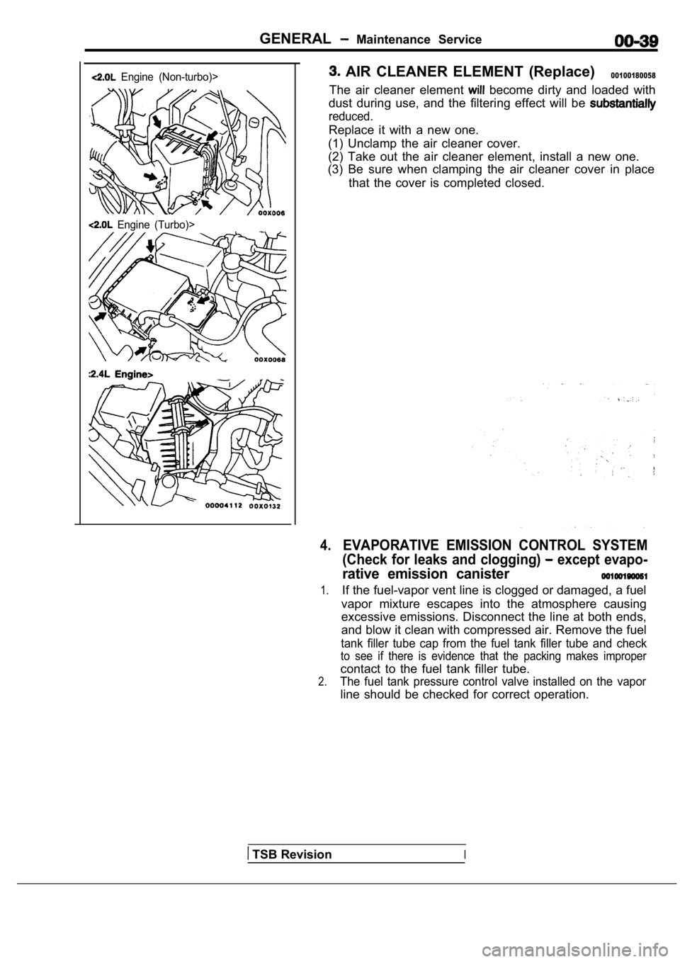
GENERAL Maintenance Service
Engine (Non-turbo)>
Engine (Turbo)>
AIR CLEANER ELEMENT (Replace)00100180058
The air cleaner element become dirty and loaded with
dust during use, and the filtering effect will be
reduced.
Replace it with a new one.
(1) Unclamp the air cleaner cover.
(2) Take out the air cleaner element, install a new one.
(3) Be sure when clamping the air cleaner cover in place
that the cover is completed closed.
4.EVAPORATIVE EMISSION CONTROL SYSTEM
(Check for leaks and clogging)
except evapo-
rative emission canister
1.If the fuel-vapor vent line is clogged or damaged, a fuel
vapor mixture escapes into the atmosphere causing
excessive emissions. Disconnect the line at both en ds,
and blow it clean with compressed air. Remove the f uel
tank filler tube cap from the fuel tank filler tube and check
to see if there is evidence that the packing makes improper
contact to the fuel tank filler tube.
2.The fuel tank pressure control valve installed on the vapor
line should be checked for correct operation.
TSB RevisionI
Page 48 of 2103
GENERAL Maintenance
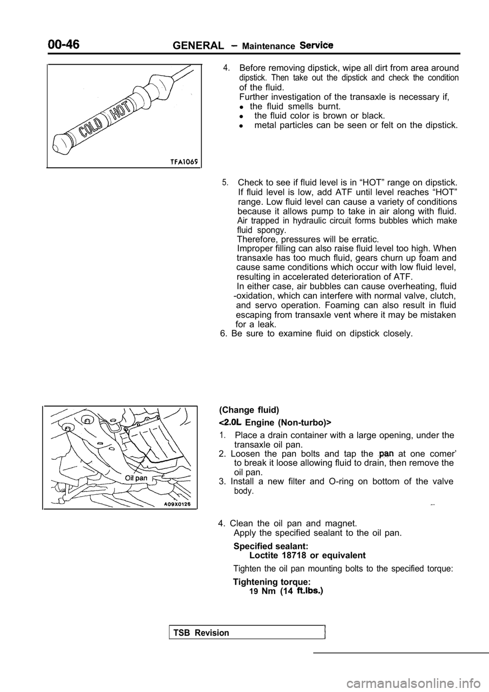
4.Before removing dipstick, wipe all dirt from area around
dipstick. Then take out the dipstick and check the condition
of the fluid.
Further investigation of the transaxle is necessary if,
l the fluid smells burnt.
l the fluid color is brown or black.
l metal particles can be seen or felt on the dipstick .
5.Check to see if fluid level is in “HOT” range on dipstick.
If fluid level is low, add ATF until level reaches “HOT”
range. Low fluid level can cause a variety of condi tions
because it allows pump to take in air along with fl uid.
Air trapped in hydraulic circuit forms bubbles which make
fluid spongy.
Therefore, pressures will be erratic. Improper filling can also raise fluid level too hig h. When
transaxle has too much fluid, gears churn up foam a nd
cause same conditions which occur with low fluid le vel,
resulting in accelerated deterioration of ATF.
In either case, air bubbles can cause overheating, fluid
-oxidation, which can interfere with normal valve, clutch,
and servo operation. Foaming can also result in flu id
escaping from transaxle vent where it may be mistak en
for a leak.
6. Be sure to examine fluid on dipstick closely.
(Change fluid)
Engine (Non-turbo)>
1.Place a drain container with a large opening, under the
transaxle oil pan.
2. Loosen the pan bolts and tap the
at one comer’
to break it loose allowing fluid to drain, then rem ove the
oil pan.
3. Install a new filter and O-ring on bottom of the valve
body.
4. Clean the oil pan and magnet.
Apply the specified sealant to the oil pan.
Specified sealant: Loctite 18718 or equivalent
Tighten the oil pan mounting bolts to the specified torque:
Tightening torque:
19Nm (14
TSB Revision
Page 66 of 2103
ENGINE,
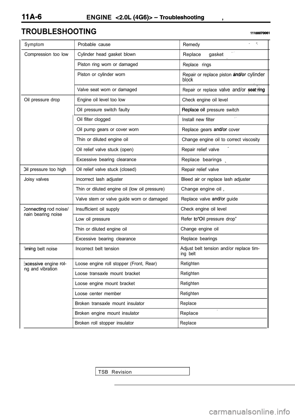
TROUBLESHOOTING
Oil filter cloggedInstall new filter
Oil pump gears or cover wornReplace gears cover
Thin or diluted engine oil Change engine oil to correct viscosity
Oil relief valve stuck (open) Repair relief valve
Excessive bearing clearanceReplace bearings
pressure too high Oil relief valve stuck (closed) Repair relief valve
Joisy valves Incorrect lash adjuster Bleed air or rep lace lash adjuster
Thin or diluted engine oil (low oil pressure)
Change engine oil ,
Valve stem or valve guide worn or damaged Replace va lve guide
rod noise/Insufficient oil supplyCheck engine oil level
nain bearing noise Low oil pressure Refer
pressure drop”
Thin or diluted engine oil Change engine oil
Excessive bearing clearance Replace bearings
belt noiseIncorrect belt tension Adjust belt tension and/or replace tim-ing belt
engine Loose engine roll stopper (Front, Rear)Retighten
ng and vibration
Loose transaxle mount bracketRetighten
Loose engine mount bracketRetighten
Loose center memberRetighten
Broken transaxle mount insulatorReplace
Broken engine mount insulatorReplace
Broken roll stopper insulatorReplace
Symptom
Probable cause
Remedy.
Compression too low Cylinder head gasket blownReplace gasket
Piston ring worn or damagedReplace rings
Piston or cylinder worn
Repair or replace piston cylinder
block
Valve seat worn or damagedRepair or replace valve and/or
Oil pressure drop Engine oil level too low Check engine oil level
Oil pressure switch faulty
pressure switch
TSB Revision
Page 177 of 2103
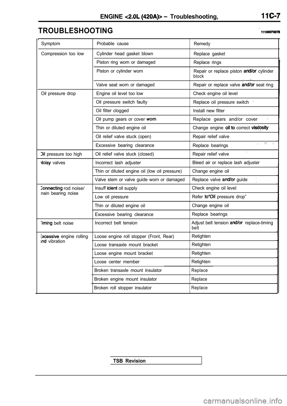
ENGINE Troubleshooting,
TROUBLESHOOTING
Symptom Probable causeRemedy
Compression too low Cylinder head gasket blown Replace gasket
Piston ring worn or damaged Replace rings
Piston or cylinder worn Repair or replace piston
cylinder
block
Valve seat worn or damaged Repair or replace valve seat ring
Oil pressure drop Engine oil level too low Check engi ne oil level
Oil pressure switch faulty Replace oil pressure switch
Oil filter clogged
Install new filter
Oil pump gears or cover
Replace gears and/or cover
Thin or diluted engine oil Change engine correct
Oil relief valve stuck (open) Repair relief valve
Excessive bearing clearance Replace bearings
pressure too highOil relief valve stuck (closed) Repair relief valve
valves Incorrect lash adjuster Bleed air or replace lash adjuster
Thin or diluted engine oil (low oil pressure) Change engine oil
Valve stem or valve guide worn or damaged Replace va lve
guide
rod noise/lnsuff oil supplyCheck engine oil level
nain bearing noise Low oil pressure Refer
pressure drop”
Thin or diluted engine oil Change engine oil
Excessive bearing clearance Replace bearings
belt noiseIncorrect belt tension
Adjust belt tension replace-timing
belt
engine rolling Loose engine roll stopper (Front, Re
ar)Retighten
vibration
Loose transaxle mount bracket Retighten
Loose engine mount bracket Retighten
Loose center member Retighten
Broken transaxle mount insulator
Replace
Broken engine mount insulatorReplace
Broken roll stopper insulatorReplace
TSB Revision
Page 213 of 2103

ENGINE OVERHAUL
Items
Engine coolant temperature sensor
Fuel and emission control parts
EGR tube
EGR valve
Intake manifold
11 8
Intake manifold air temperature sensor
Manifold absolute pressure sensor
Intake manifold
Exhaust manifold
Exhaust manifold
Camshaft and cam follower
Cvlinder head cover
Bearing head cover
No.5 12
No.1, 628 20
Cvlinder head and
valve.
7
21 . 4
231 7 :
23 17
Cylinder head bolt
Oil pan and oil pump
Oil filter
Adapter
Oil
Oil pick-up tube
Oil pump
Oil pump
Relief valve retaining cap
Long bolt87
Short bolt2820
21,
12
2 8
23
54
Oil pump cover
Piston, connecting rod and cylinder block
Connecting rod cap bolt
1 2
2720
Knock sensor 10I
SEALANTS
Engine coolant temperature sensor
switch
Camshaft bearing cap
Oil pump
Bed plate to oil pan gasket
Oil pressure switch Bed plate to cylinder block Specified sealant
Loctite 24200 or equivalent
Loctite 24200 or equivalent
Loctite 51817 or equivalent
Loctite 51817 or equivalent
Loctite 18718 or equivalent
Loctite 24200 or equivalent
Loctite 19614 or equivalent
TSB Revision
Page 274 of 2103
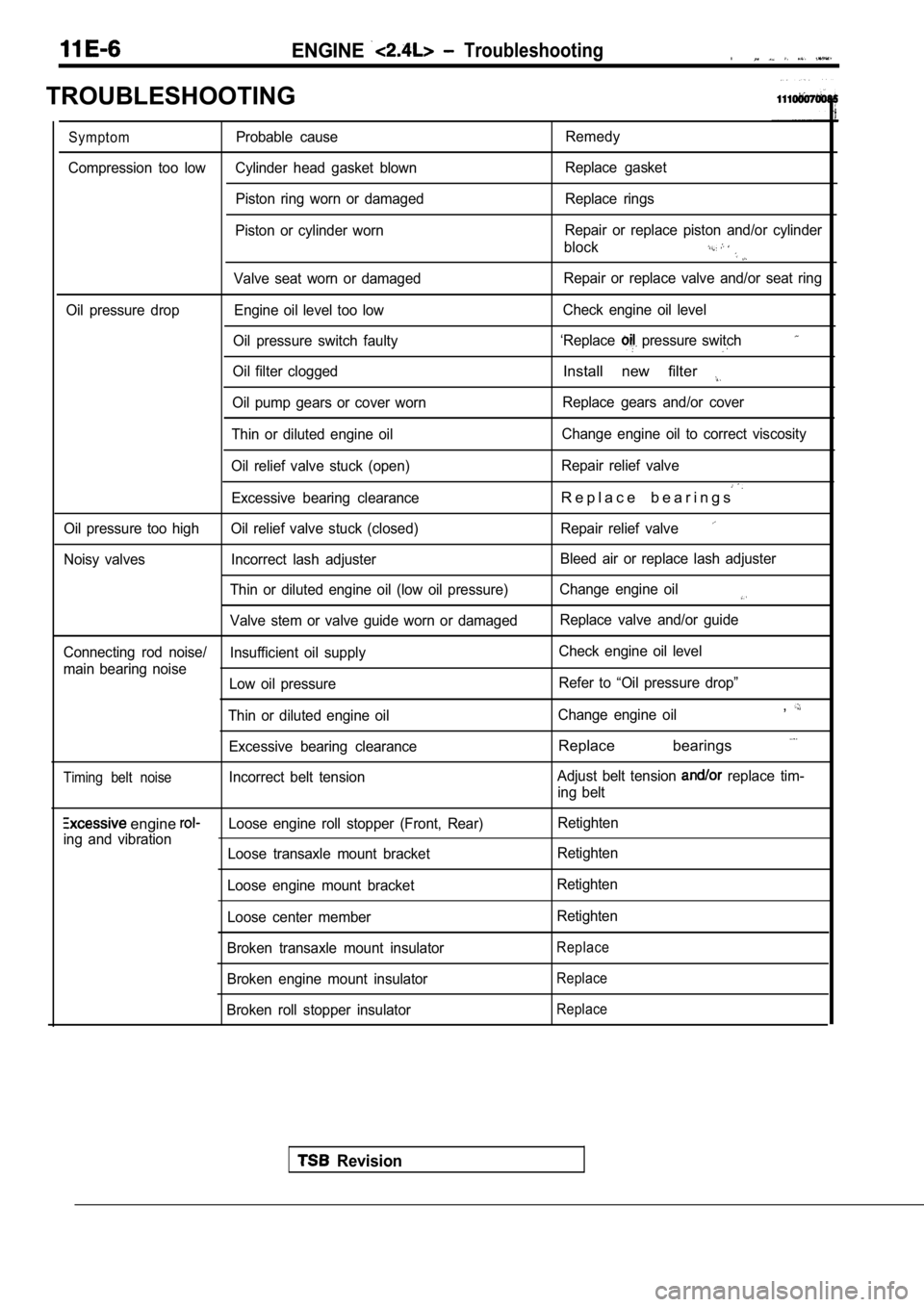
ENGINE Troubleshooting.
TROUBLESHOOTING
SymptomProbable causeRemedy
Compression too low Cylinder head gasket blown Replace gasket
Piston ring worn or damaged Replace rings
Piston or cylinder worn Repair or replace piston and/or cylinder
block
Valve seat worn or damaged Repair or replace valve and/or seat ring
Oil pressure drop Engine oil level too low Check engine oil level
Oil pressure switch faulty ‘Replace
pressure switch
Oil filter cloggedInstall new filter
Oil pump gears or cover worn Replace gears and/or cover
Thin or diluted engine oil Change engine oil to correct viscosity
Oil relief valve stuck (open) Repair relief valve
Excessive bearing clearanceR e p l a c e b e a r i n g s
Oil pressure too high Oil relief valve stuck (closed
) Repair relief valve
Noisy valves Incorrect lash adjuster Bleed air or replace lash adjuster
Thin or diluted engine oil (low oil pressure) Change engine oil
Valve stem or valve guide worn or damaged Replace valve and/or guide
Connecting rod noise/ Insufficient oil supply Check engine oil level
main bearing noise Low oil pressure Refer to “Oil pressure drop”
Thin or diluted engine oil Change engine oil
,
Excessive bearing clearanceReplace bearings
Timing belt noiseIncorrect belt tensionAdjust belt tension replace tim-
ing belt
engine Loose engine roll stopper (Front, Rear) Retighten
ing and vibration Loose transaxle mount bracket Retighten
Loose engine mount bracket Retighten
Loose center member Retighten
Broken transaxle mount insulator
Replace
Broken engine mount insulatorReplace
Broken roll stopper insulatorReplace
Revision
Page 441 of 2103
![MITSUBISHI SPYDER 1990 Service Repair Manual ENGINE (NON-TURBO)>
Scan tool 106
Code General scan tool
No.Multiple Cylinder Mlsfire
43
[Comment]Background
l Excessive engine misfire results in increased catal yst temperature. MITSUBISHI SPYDER 1990 Service Repair Manual ENGINE (NON-TURBO)>
Scan tool 106
Code General scan tool
No.Multiple Cylinder Mlsfire
43
[Comment]Background
l Excessive engine misfire results in increased catal yst temperature.](/manual-img/19/57345/w960_57345-440.png)
ENGINE (NON-TURBO)>
Scan tool 106
Code General scan tool
No.Multiple Cylinder Mlsfire
43
[Comment]Background
l Excessive engine misfire results in increased catal yst temperature.
l Severe misfire could cause catalyst damage.
l To prevent catalytic converter damage, the PCM moni tors engine misfire.
l The PCM monitors for misfire during most engine ope rating conditions.
lWhen a misfire is detected, the PCM stores a diagnostic trouble code and causes the to either flash or illuminate continuously during active misfire.
Range of Check
l MAP voltage is less than 1.60
l Engine speed is between 2200 and 2800 l Engine coolant temperature is greater than l Vehicle speed less than Set Condition
l 1000 Rev Misfire
The PCM detects misfire in more than 1.6% of the en gine cycles in a 1000 revolution
period.l 200 Rev MisfireThe PCM detects misfire in more than 15% of the eng ine cycles in a 200 revolution period.
.
Spark plugs or wires failed
l Ignition coil failed
l Crankshaft position piston rings v a l v e s
l Head gasket failed
l C r a c k e d
l Fuel lines and filter failed
l Fuel failed
l failed
l Wiring and connectors failed
l Engine coolant
l Timing belt tooth broken,
l EGR
SCAN TOOL SENSOR READ TESTS (Data list)
05 Engine coolant temperature sensor (Refer to Check the engine coolant temperature circuit.
(Refer to INSPECTION PROCEDURE 38.)
OK
SCAN TOOL SENSOR READ TESTS (Data list)
27 Intake air temperature sensor (Refer to
OK
Check the intake air temperaturecircuit.(Refer to INSPECTION PROCEDURE
SCAN TOOL SENSOR READ TESTS (Data list)
11 MAP sensor reading (Refer to
OK
OK
Check the MAP sensor circuit.(Refer to INSPECTION PROCEDURE 40.)
SCAN TOOL SENSOR READ TESTS (Data list)
Check the following connectors: 66 Oxygen sensor volts (front) (Refer to OK: Repeat and alternately whenidling.
Check the fuel pressure. (Refer to Check the harness wire between the PCM and the cran kshaft
position sensor connector.
l Check the injectors for operation sound.
l Check the injectors for fuel leakage.
l Check the evaporative emission control system.
Check the following items.
l Check the ignition coil, spark plug cables.
l Check the compression pressure.
Check the EGR
TSB Revision