1990 MITSUBISHI SPYDER spark plugs
[x] Cancel search: spark plugsPage 3 of 2103

CONTENTS
GENERAL DATA AND SPECIFICATIONS. .
HOW TO USE THIS MANUAL. . . . . . . . . . . . .3
Explanation of Manual Contents. . . . . . . . . . . . . .4
Model Indications
. . . . . . . . . . . . . . . . . . . . . . . . . . .3
Maintenance, Repair and
Servicing Explanations. . . . . . . . . . . . . . . . . . . . . . .
3
Special Tool Note. . . . . . . . . . . . . . . . . . . . . . . . . . .3
Terms Definition. . . . . . . . . . . . . . . . . . . . . . . . . . . .3
Tightening Torque Indication. . . . . . . . . . . . . . . . .3
HOW TO USE TROUBLESHOOTING/
INSPECTION SERVICE POINTS. . . . . . . . . . . .6
Connector Inspection Service Points
. . . . . . . . . .10
Connector Measurement Service Points . . . . . . . .9
How to Cope with Intermittent Malfunctions . . .11
How to Use the Inspection Procedures
. . . . . . .
8
Inspection Service Points for a Blown Fuse . . .
12
Troubleshooting Contents. . . . . . . . . . . . . . . . . . . .6
LUBRICATION AND MAINTENANCE . . . . . . .33
MAIN SEALANT AND ADHESIVE TABLE
. .
MAINTENANCE SERVICE. . . . . . . . . . . . . . . . . .38
Air Cleaner Element. . . . . . . . . . . . . . . . . . . . . . . .39
Automatic Transaxle Fluid
. . . . . . . . . . . . . . . . . . .45
Ball Joint and Steering Linkage Seals
. . . . . . . .50
Brake Hoses.... . . . . . . . . . . . . . . . . . . . . . . . . . . .50
Disc Brake Pads. . . . . . . . . . . . . . . . . . . . . . . . . . . .49
Drive Belt (For Generator, Water Pump, Power
Steering Pump). . . . . . . . . . . . . . . . . . . . . . . . . . . . .40
Drive Shaft Boots
. . . . . . . . . . . . . . . . . . . . . . . . . . .50
Engine Coolant. . . . . . . . . . . . . . . . . . . . . . . . . . . . .48
Engine Oil. . . . . . . . . . . . . . . . . . . . . . . . . . . . . . . . . .42
Engine Oil Filter. . . . . . . . . . . . . . . . . . . . . . . . . . . .43
Evaporative Emission Control System . . . . . . . . .
Exhaust System. . . . . . . . . . . . . . . . . . . . . . . . . . . . .54
Fuel Hoses. . . . . . . . . . . . . . . . . . . . . . . . . . . . . . . . .38
Fuel System. . . . . . . . . . . . . . . . . . . . . . . . . . . . . . . .38
Ignition Cables. . . . . . . . . . . . . . . . . . . . . . . . . . . . . .
40
Manual Transaxle Oil . . . . . . . . . . . . . . . . . . . . . . . .
Rear Axle Oil. . . . . . . . . . . . . . . . . . . . . . . . . . . .
50
Rear Drum Brake Linings and
Rear Wheel Cylinders . . . . . . . . . . . . . . . . . . . . . . .
Spark Plugs. . . . . . . . . . . . . . . . . . . . . . . . . . . . . . . .40
SRS System . . . . . . . . . . . . . . . . . . . . . . . . . . . . . . .51
Timing Belt. . . . . . . . . . . . . . . . . . . . . . . . . . . . . . . . .40
Transfer Oil. . . . . . . . . . . . . . . . . . . . . . . . . . . . . . . .48
PRECAUTIONS BEFORE SERVICE. . . . . . . .20
RECOMMENDED LUBRICANTS
LUBRICANT CAPACITIES TABLE. . . . . . . . . .34
SCHEDULED MAINTENANCE TABLE. . . . .
SPECIAL HANDLING INSTRUCTIONS FOR
AWD MODELS . . . . . . . . . . . . . . . . . . . . . . . . . . . .
26
TIGHTENING TORQUE. . . . . . . . . . . . . . . . . . . .32
TOWING AND HOISTING . . . . . . . . . . . . . . . . . .22
VEHICLE IDENTIFICATION. . . . . . . . . . . . . . . . .13
Engine Model Stamping. . . . . . . . . . . . . . . . . . . . .15
Theft Protection. . . . . . . . . . . . . . . . . . . . . . . . . . . . .18
Vehicle Identification Code Chart Plate
. . . . . . .13
Vehicle Identification Number List. . . . . . . . . . . .14
Vehicle Identification Number Location. . . . . . . .13
Vehicle Information Code Plate.. . . . . . . . . . . . . .15
Vehicle Safety Certification Label
. . . . . . . . . . . . .15
Page 42 of 2103

GENERAL Maintenance
Incorrect Correct
5. SPARK PLUGS
1.Spark plugs must spark properly to assure proper engine
performance and reduce exhaust emission
Therefore, they should be periodically with new
ones.
2. The new plugs should be checked gap.
Spark plug gap:, . .
Engine (Turbo)>’
mm
Engine (Non-turbo)> ,
1.22-1.35 mm
in.)
Engine> .
in.)
3. Install the spark plug and tighten to the
Tightening torque:
Engine (Turbo) and Engine>
25 Nm (18
E n g i n e ( N o n - t u r b o ) >
28 Nm (20
6. IGNITION CABLES (Replace)
The ignition cables should. be replaced periodicall y with new
ones. After replacing, make sure that the ignition cables are
routed properly and fully seated.
NOTE
When disconnecting an ignition cable; be sure to ho ld the
cable boot. If the cable is disconnected by pulling on the
cable alone, an open circuit might result.
7. TIMING BELT (Replace)
00100220027
Replace the belt with a new one periodically to ass ure proper
engine performance.
For disassembly and assembly procedures; Refer to GROUP
Timing Belt.
Refer to GROUP
Timing Belt.
Refer to GROUP 11
Timing Belt.
8. DRIVE BELT (For Generator, Water Pump, Power Steering Pump) (Check condition)
Check the tension of the drive belt. Check the driv e belt
for evidence of cuts and cracks, and replace it if defective.
TSB Revision
Page 71 of 2103

ENGINE On-vehicle
8. If the standard value is exceeded, check the following
items:
l Diagnostic output
l Closed-loop control (When the closed-loop control
is carried out normally, the output signal of the h eated
oxygen sensor repeats between and
,000 at idle.)
l Fuel pressure
I n j e c t o r
lIgnition coil, spark plug cable, spark plug
lEGR system and the EGR valve leak
l Evaporative emission control system
Compression pressure
NOTE
Replace the catalyst whenever the
HC contents do not remain inside the standard value .
(even though the result of the inspection is
all items.).
C O M P R E S S I O N
CHECK
1.Before inspection, check that the engine-oil, start er
battery are normal. Also, set the to the
condition:
lEngine coolant temperature:
lLights, electric cooling fan and all accessories: O FF
lTransaxle: Neutral (P range on vehicles with
2. Disconnect the spark plug cables.
3. Remove all of the spark plugs.
4.
5.
Disconnect the crankshaft position sensor connector .
NOTE
Doing this will prevent the engine control unit fro m carrying
out ignition and fuel injection.
Cover the spark plug hole with a shop towel etc., a nd
after the engine has been cranked, check that no fo reign
material is adhering to the shop towel.
TSB Revision
Page 72 of 2103

ENGINE On-vehicle
Caution
1.Keep away from the spark plug hole when crank-
ing.
2. If compression is measured with water, oil, fuel,
etc., that has come from cracks inside the cylinder ,
these materials will become heated and will gush
out from the spark plug hole, which is dangerous.
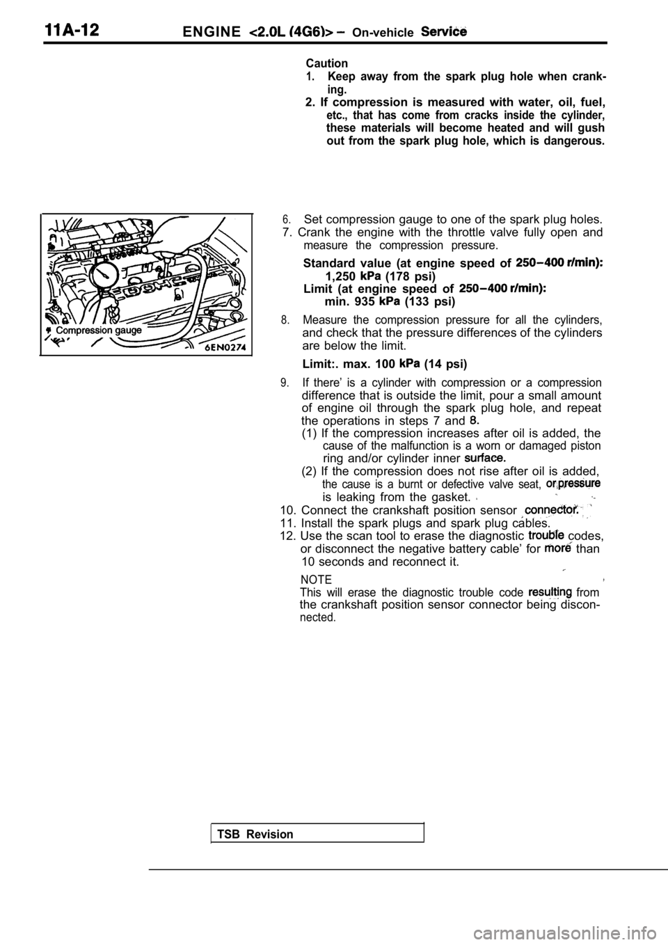
6.Set compression gauge to one of the spark plug hole s.
7. Crank the engine with the throttle valve fully o pen and
measure the compression pressure.
Standard value (at engine speed of
1,250 (178 psi)
Limit (at engine speed of
min. 935 (133 psi)
8.Measure the compression pressure for all the cylind ers,
and check that the pressure differences of the cylinders
are below the limit.
Limit:. max. 100
(14 psi)
9.If there’ is a cylinder with compression or a compr ession
difference that is outside the limit, pour a small amount
of engine oil through the spark plug hole, and repe at
the operations in steps 7 and
(1) If the compression increases after oil is added , the
cause of the malfunction is a worn or damaged pisto n
ring and/or cylinder inner
(2) If the compression does not rise after oil is added,
the cause is a burnt or defective valve seat,
is leaking from the gasket.
10. Connect the crankshaft position sensor
11. Install the spark plugs and spark plug cables.
12. Use the scan tool to erase the diagnostic
codes,
or disconnect the negative battery cable’ for
than
10 seconds and reconnect it.
NOTE
This will erase the diagnostic trouble code from
the crankshaft position sensor connector being disc on-
nected.
TSB Revision
Page 181 of 2103

ENGINE On-vehicle Service
IDLE MIXTURE CHECK
11100210081
1.Before inspection, set vehicles in the following co ndition:
lEngine coolant temperature:
l Lights, electric cooling fan and all accessories: O FF
lTransaxle: Neutral (P range on vehicles with
2.After turning the ignition switch to OFF, connect t he scan
tool to the data link connector.
3.Start the engine and run it at 2,500 for 2 minutes.
4. Set the CO, HC tester.
5. Check the CO contents and the HC contents at idl e.
Standard value:
CO contents: 0.5% or less
HC contents: 100 ppm or less
6. If the idle speed is outside the standard value, check
the following items: l Diagnostic output
l Closed-loop control (When the closed-loop control
is carried out normally, the output signal of the h eated
oxygen sensor repeats between and
,000 at idle.)
l Fuel pressure
I n j e c t o r
lIgnition coil, spark plug cable, spark plug
lEGR system and the EGR valve leak
l Evaporative emission control system
Compression pressure
NOTE
Replace the three-way catalyst whenever the CO and
HC contents do not remain inside the standard value .
(even though the result of the inspection is normal on
all items.)
COMPRESSION PRESSURE CHECK
1.Before inspection, check that the engine oil, start er and
battery are normal. Also, set the vehicle to the fo llowing
condition:
lEngine coolant temperature:
lLights, electric cooling fan and all accessories: O FF
lTransaxle: Neutral (P range on vehicle with
2. Disconnect the spark plug cables.
3. Remove all spark plugs.
4.Disconnect the relay (ASD relay) connector to prevent
a spark.
4 4
Revision
Page 220 of 2103

ENGINE OVERHAUL
.
INSTALLATION
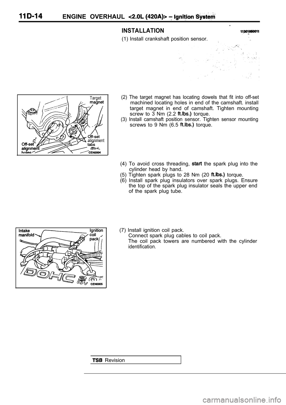
(1) Install crankshaft position sensor.
Target
alignment
(2) The target magnet has locating dowels that fit into off-set
machined locating holes in end of the camshaft. ins tall
target magnet in end of camshaft. Tighten mounting
screw to 3 Nm (2.2
torque.
(3) Install camshaft position sensor. Tighten senso r mounting
screws to 9 Nm (6.5 torque.
(4) To avoid cross threading,
the spark plug into the
cylinder head by hand.
(5) Tighten spark plugs to 28 Nm (20
torque.
(6) Install spark plug insulators over spark plugs. Ensure
the top of the spark plug insulator seals the upper end
of the spark plug tube.
(7) Install ignition coil pack. Connect spark plug cables to coil pack.
The coil pack towers are numbered with the cylinder
identification.
Revision
Page 279 of 2103

On-vehicle
Run the engine.
8. Set CO, HC tester.
7. Check the CO contents and the HC contents at idle.
Standard value:
CO contents: 0.5% or less
HC contents: 100 ppm or less
8. the standard value is exceeded, check the following
items:
l Diagnostic output
l Closed-loop control (When the closed-loop control
is carried out normally, the output signal of the heated
oxygen sensor and
at idle.)
l
Injector
lIgnition coil, spark plug
l system the
l Evaporative emission
Compression ,
NOTE,
Replace the three-way CO and
HC contents do not
the value.
(even though the
of the” on
all items.)
PRESSURE CHECK
1.Before inspection, check that the engine oil, start er and
battery are normal. Also, set the vehicle to the fo llowing
condition:
lEngine coolant temperature:
lLights, electric cooling fan and all accessories: O FF
lTransaxle: Neutral (P range on vehicles with
2. Disconnect the spark plug cables.
3. Remove all of the spark plugs.
4. Disconnect the crankshaft position sensor
NOTE
Doing this will prevent the engine control unit fro m carrying
out ignition and fuel injection.
TSB Revision
Page 280 of 2103

ENGINEOn-vehicle
5. Cover the spark plug hole with a shop towel etc., and
after the engine has been cranked, check that no foreign
material is adhering to the shop towel.
Caution
1.Keep away from the spark plug hole when crank-
ing.
2. If compression is measured with water, fuel,
etc., that has come from cracks inside the
these materials will become heated and gush
out from the spark plug hole, which is dangerous.
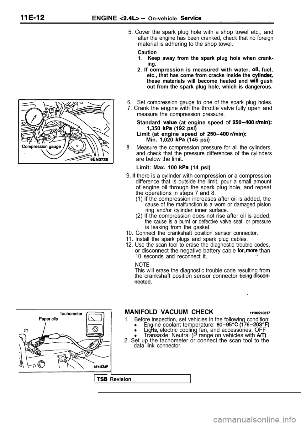
6.Set compression gauge to one of the spark plug hole s.
7. Crank the engine with the throttle valve fully open and
measure the compression pressure.
Standard (at engine speed of
1,350 (192 psi)
Limit (at engine speed of
Min. 1,020 (145 psi)
8.Measure the compression pressure for all the cylind ers,
and check that the pressure differences of the cyli nders
are below the limit.
Limit: Max. 100 (14 psi)
9. there is a cylinder with compression or a compression
difference that is outside the limit, pour a small amount
of engine oil through the spark plug hole, and repe at
the operations in steps 7 and 8.
(1) If the compression increases after oil is added , the
cause of the malfunction is a worn or damaged pisto n
ring and/or cylinder inner surface.
(2) If the compression does not rise after oil is added,
the cause is a burnt or defective valve seat, or pr essure
is leaking from the gasket.
10. Connect the crankshaft position sensor connecto r.
11. Install the spark plugs and spark plug cables.
12. Use the scan tool to erase the diagnostic troub le codes,
or disconnect the negative battery cable than
10 seconds and reconnect it.
NOTE
This will erase the diagnostic trouble code resulting from
the crankshaft position sensor connector
MANIFOLD VACUUM CHECK
1.Before inspection, set vehicles in the following co ndition:
lEn
lLig electric cooling fan, and accessories: OFF
ine coolant temperature:
lTransaxle: Neutral (P range on vehicles with
2. Set up the tachometer or connect the scan tool t o the
data link connector.
Revision