1990 MITSUBISHI SPYDER brake pads
[x] Cancel search: brake padsPage 3 of 2103
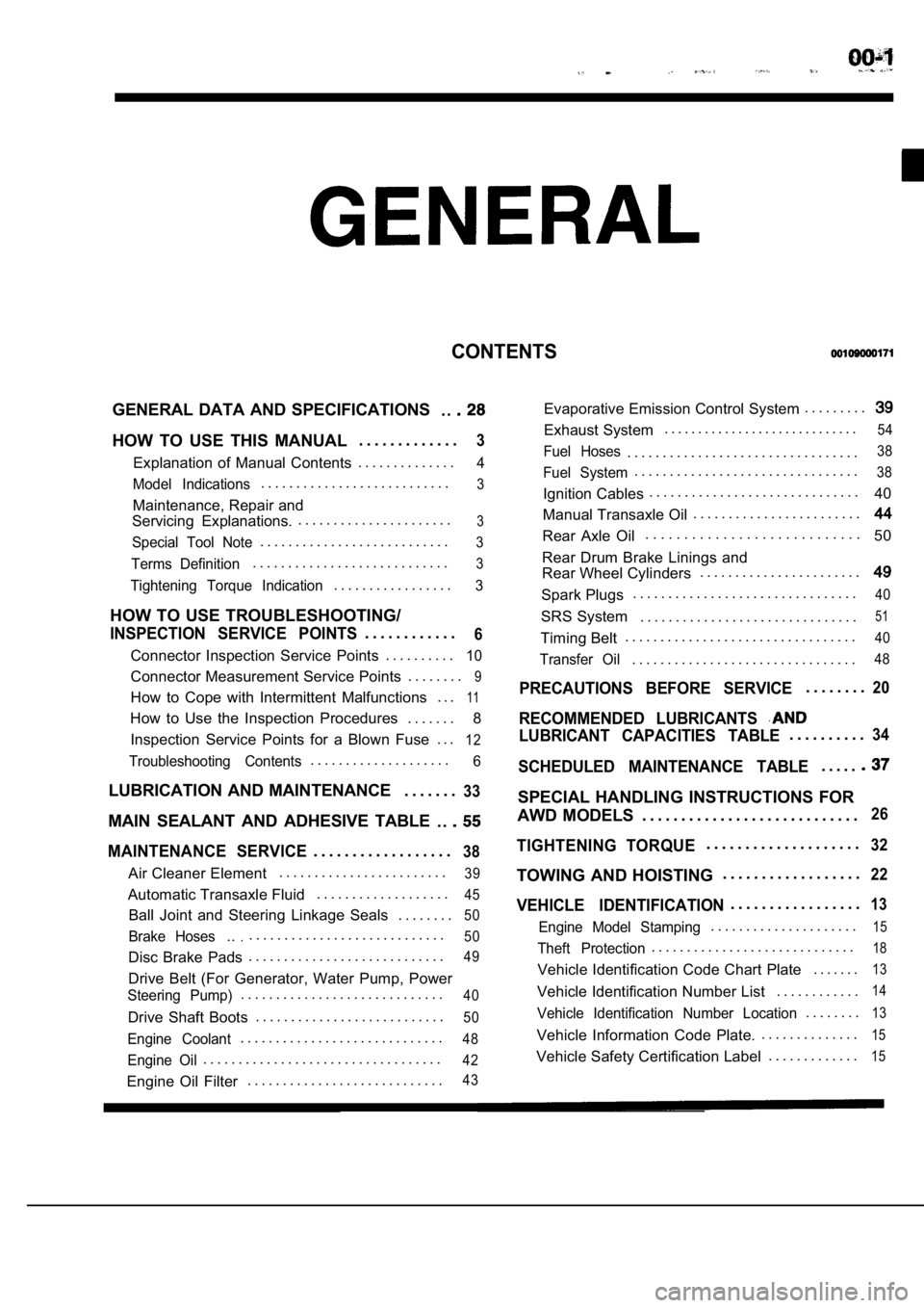
CONTENTS
GENERAL DATA AND SPECIFICATIONS. .
HOW TO USE THIS MANUAL. . . . . . . . . . . . .3
Explanation of Manual Contents. . . . . . . . . . . . . .4
Model Indications
. . . . . . . . . . . . . . . . . . . . . . . . . . .3
Maintenance, Repair and
Servicing Explanations. . . . . . . . . . . . . . . . . . . . . . .
3
Special Tool Note. . . . . . . . . . . . . . . . . . . . . . . . . . .3
Terms Definition. . . . . . . . . . . . . . . . . . . . . . . . . . . .3
Tightening Torque Indication. . . . . . . . . . . . . . . . .3
HOW TO USE TROUBLESHOOTING/
INSPECTION SERVICE POINTS. . . . . . . . . . . .6
Connector Inspection Service Points
. . . . . . . . . .10
Connector Measurement Service Points . . . . . . . .9
How to Cope with Intermittent Malfunctions . . .11
How to Use the Inspection Procedures
. . . . . . .
8
Inspection Service Points for a Blown Fuse . . .
12
Troubleshooting Contents. . . . . . . . . . . . . . . . . . . .6
LUBRICATION AND MAINTENANCE . . . . . . .33
MAIN SEALANT AND ADHESIVE TABLE
. .
MAINTENANCE SERVICE. . . . . . . . . . . . . . . . . .38
Air Cleaner Element. . . . . . . . . . . . . . . . . . . . . . . .39
Automatic Transaxle Fluid
. . . . . . . . . . . . . . . . . . .45
Ball Joint and Steering Linkage Seals
. . . . . . . .50
Brake Hoses.... . . . . . . . . . . . . . . . . . . . . . . . . . . .50
Disc Brake Pads. . . . . . . . . . . . . . . . . . . . . . . . . . . .49
Drive Belt (For Generator, Water Pump, Power
Steering Pump). . . . . . . . . . . . . . . . . . . . . . . . . . . . .40
Drive Shaft Boots
. . . . . . . . . . . . . . . . . . . . . . . . . . .50
Engine Coolant. . . . . . . . . . . . . . . . . . . . . . . . . . . . .48
Engine Oil. . . . . . . . . . . . . . . . . . . . . . . . . . . . . . . . . .42
Engine Oil Filter. . . . . . . . . . . . . . . . . . . . . . . . . . . .43
Evaporative Emission Control System . . . . . . . . .
Exhaust System. . . . . . . . . . . . . . . . . . . . . . . . . . . . .54
Fuel Hoses. . . . . . . . . . . . . . . . . . . . . . . . . . . . . . . . .38
Fuel System. . . . . . . . . . . . . . . . . . . . . . . . . . . . . . . .38
Ignition Cables. . . . . . . . . . . . . . . . . . . . . . . . . . . . . .
40
Manual Transaxle Oil . . . . . . . . . . . . . . . . . . . . . . . .
Rear Axle Oil. . . . . . . . . . . . . . . . . . . . . . . . . . . .
50
Rear Drum Brake Linings and
Rear Wheel Cylinders . . . . . . . . . . . . . . . . . . . . . . .
Spark Plugs. . . . . . . . . . . . . . . . . . . . . . . . . . . . . . . .40
SRS System . . . . . . . . . . . . . . . . . . . . . . . . . . . . . . .51
Timing Belt. . . . . . . . . . . . . . . . . . . . . . . . . . . . . . . . .40
Transfer Oil. . . . . . . . . . . . . . . . . . . . . . . . . . . . . . . .48
PRECAUTIONS BEFORE SERVICE. . . . . . . .20
RECOMMENDED LUBRICANTS
LUBRICANT CAPACITIES TABLE. . . . . . . . . .34
SCHEDULED MAINTENANCE TABLE. . . . .
SPECIAL HANDLING INSTRUCTIONS FOR
AWD MODELS . . . . . . . . . . . . . . . . . . . . . . . . . . . .
26
TIGHTENING TORQUE. . . . . . . . . . . . . . . . . . . .32
TOWING AND HOISTING . . . . . . . . . . . . . . . . . .22
VEHICLE IDENTIFICATION. . . . . . . . . . . . . . . . .13
Engine Model Stamping. . . . . . . . . . . . . . . . . . . . .15
Theft Protection. . . . . . . . . . . . . . . . . . . . . . . . . . . . .18
Vehicle Identification Code Chart Plate
. . . . . . .13
Vehicle Identification Number List. . . . . . . . . . . .14
Vehicle Identification Number Location. . . . . . . .13
Vehicle Information Code Plate.. . . . . . . . . . . . . .15
Vehicle Safety Certification Label
. . . . . . . . . . . . .15
Page 51 of 2103
GENERAL Maintenance
a
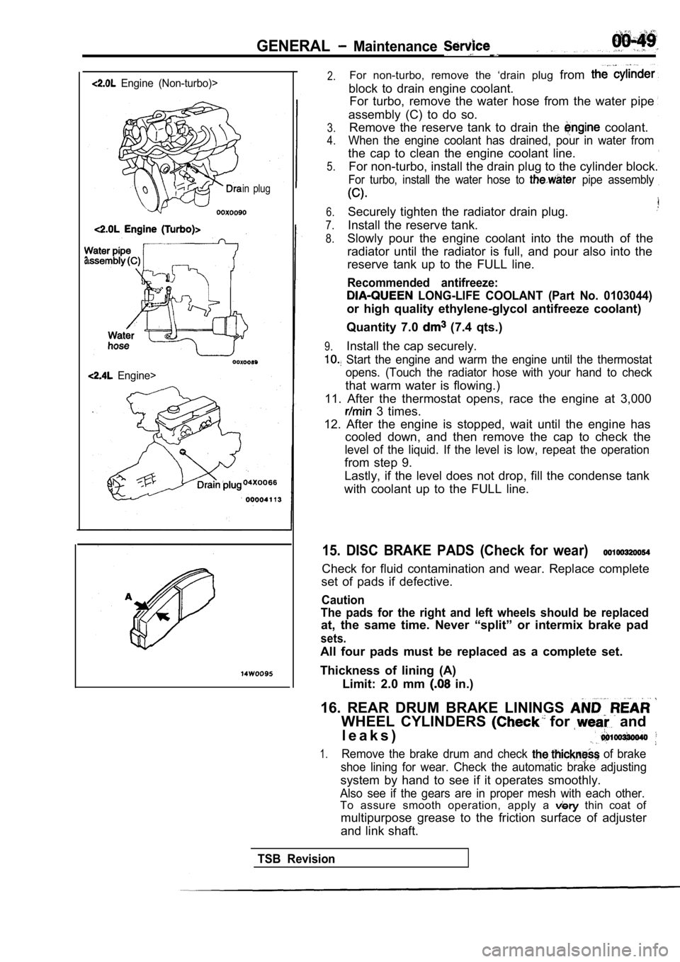
Engine (Non-turbo)>
in plug
Engine>
2.For non-turbo, remove the ‘drain plug from
block to drain engine coolant.
For turbo, remove the water hose from the water pip e
assembly (C) to do so.
3.
4.
5.Remove the reserve tank to drain the coolant.
When the engine coolant has drained, pour in water from
the cap to clean the engine coolant line.
For non-turbo, install the drain plug to the cylind er block.
For turbo, install the water hose to pipe assembly
6.
7.
8.
Securely tighten the radiator drain plug.
Install the reserve tank.
9.
Slowly pour the engine coolant into the mouth of th e
radiator until the radiator is full, and pour also into the
reserve tank up to the FULL line.
Recommended antifreeze:
LONG-LIFE COOLANT (Part No. 0103044)
or high quality ethylene-glycol antifreeze coolant)
Quantity 7.0
(7.4 qts.)
Install the cap securely.
Start the engine and warm the engine until the the rmostat
opens. (Touch the radiator hose with your hand to c heck
that warm water is flowing.)
11. After the thermostat opens, race the engine at 3,000
3 times.
12. After the engine is stopped, wait until the eng ine has
cooled down, and then remove the cap to check the
level of the liquid. If the level is low, repeat th e operation
from step 9.
Lastly, if the level does not drop, fill the conden se tank
with coolant up to the FULL line.
15. DISC BRAKE PADS (Check for wear)
Check for fluid contamination and wear. Replace com plete
set of pads if defective.
Caution
The pads for the right and left wheels should be re placed
at, the same time. Never “split” or intermix brake pad
sets.
All four pads must be replaced as a complete set.
Thickness of lining (A) Limit: 2.0 mm
in.)
16. REAR DRUM BRAKE LININGS
WHEEL CYLINDERS for and
l e a k s )
1.Remove the brake drum and check of brake
shoe lining for wear. Check the automatic brake adj usting
system by hand to see if it operates smoothly.
Also see if the gears are in proper mesh with each other.
To assure smooth operation, apply a thin coat of
multipurpose grease to the friction surface of adju ster
and link shaft.
TSB Revision
Page 1644 of 2103
BASIC BRAKE SYSTEM
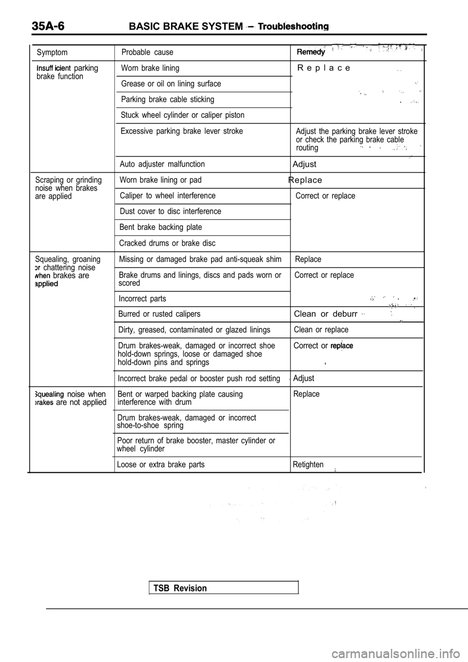
Symptom
parking
brake functionProbable cause
Worn brake lining
R e p l a c e
Grease or oil on lining surface
Parking brake cable sticking
Stuck wheel cylinder or caliper piston.
Scraping or grinding
noise when brakes
are applied Excessive parking brake lever stroke
Auto adjuster malfunction
Worn brake lining or pad Caliper to wheel interference
Dust cover to disc interference Adjust the parking brake lever stroke
or check the parking brake cable
routing
.
Adjust
R e p l a c e
Correct or replace
Bent brake backing plate
Cracked drums or brake disc
Squealing, groaning
chattering noise
brakes are
Missing or damaged brake pad anti-squeak shim Replac e
Brake drums and linings, discs and pads worn or Corr ect or replace
scored
Incorrect parts
.
Burred or rusted calipersClean or deburr
Dirty, greased, contaminated or glazed linings Clean or replace
Drum brakes-weak, damaged or incorrect shoe
hold-down springs, loose or damaged shoe
Correct or
hold-down pins and springs,
Incorrect brake pedal or booster push rod setting Adjust
noise whenBent or warped backing plate causing Replace
are not appliedinterference with drum
Drum brakes-weak, damaged or incorrect
shoe-to-shoe spring
Poor return of brake booster, master cylinder or
wheel cylinder
Loose or extra brake parts Retighten
TSB Revision
Page 1645 of 2103
BASIC BRAKE SYSTEM Troubleshooting .
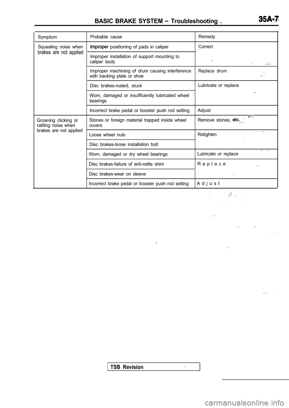
SymptomProbable cause Remedy
Squealing noise when
positioning of pads in caliper Correct
brakes are not appliedImproper installation of support mounting to
caliper body
Improper machining of drum causing interferenceReplace drum
with backing plate or shoe
Disc brakes-rusted, stuck Lubricate or replace
Worn, damaged or insufficiently lubricated wheel
bearings
Incorrect brake pedal or booster push rod setting Adjust
Groaning clicking orStones or foreign material trapped inside wheel
Remove stones,
rattling noise when covers
brakes are not applied
Loose wheel nuts Retighten
Disc brakes-loose installation bolt
Worn, damaged or dry wheel bearings Lubricate or replace
Disc brakes-failure of anti-rattle shim
R e p l a c e
Disc brakes-wear on sleeve
Incorrect brake pedal or booster push rod settingA d j u s t
,
TSB Revision
Page 1652 of 2103
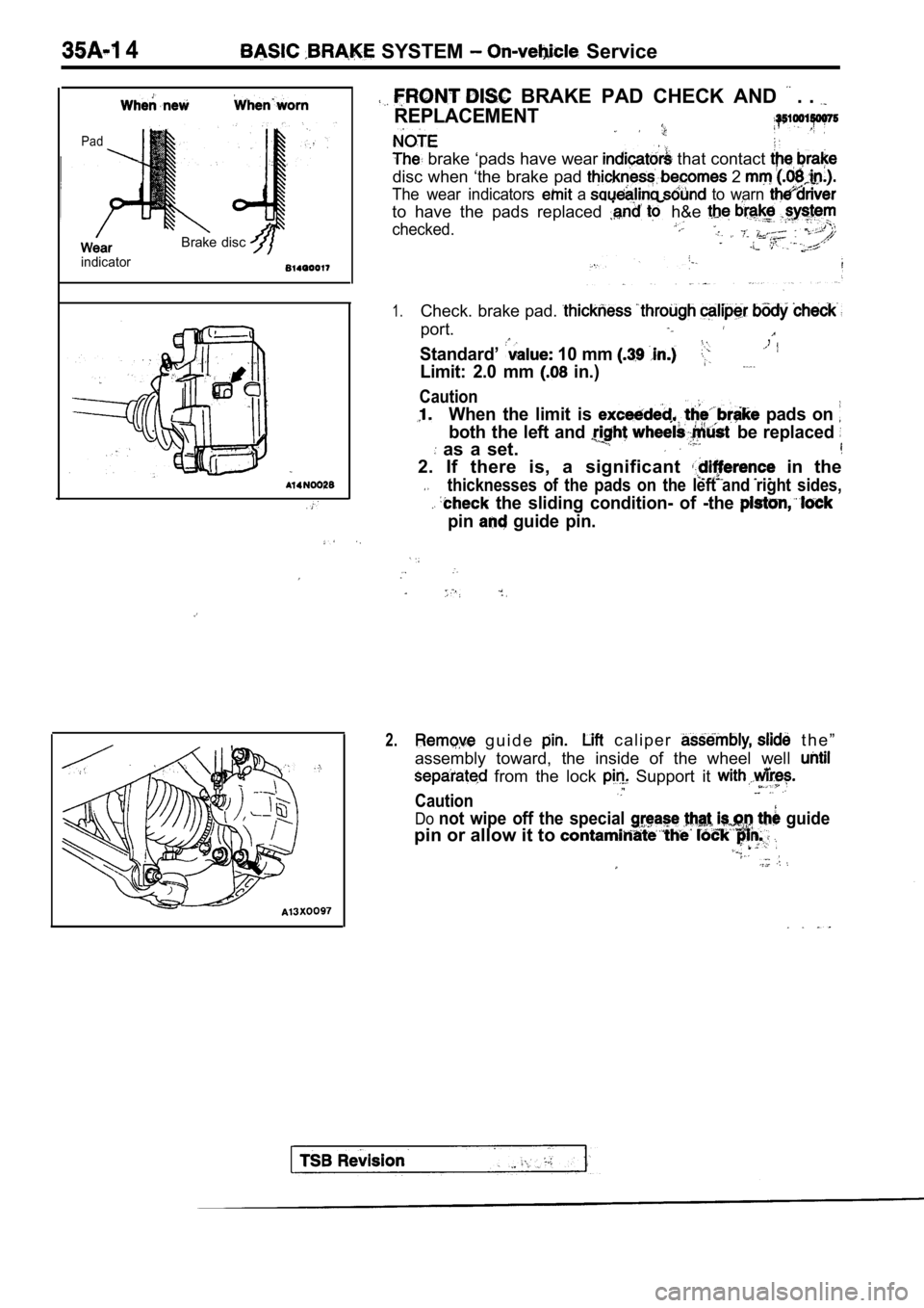
4 SYSTEM Service
Pad
indicator
Brake disc
BRAKE PAD CHECK AND . .
REPLACEMENT
brake ‘pads have wear that contact
disc when ‘the brake pad 2
The wear indicators a to warn
to have the pads replaced h&e
checked.
1.Check. brake pad.
port.
Standard’ 10 mm
,
Limit: 2.0 mm in.)
Caution
When the limit is pads on
both the left and be replaced
as a set.
2. If there is, a significant in the
thicknesses of the pads on the left and right sides,
the sliding condition- of -the
pin guide pin.
2. g u i d e c a l i p e r t h e ”
assembly toward, the inside of the wheel well
from the lock Support it
Caution
Donot wipe off the special guide
pin or allow it to
Page 1653 of 2103
BASIC BRAKE SYSTEM
Front hub assembly
196-255 Nm
145-188
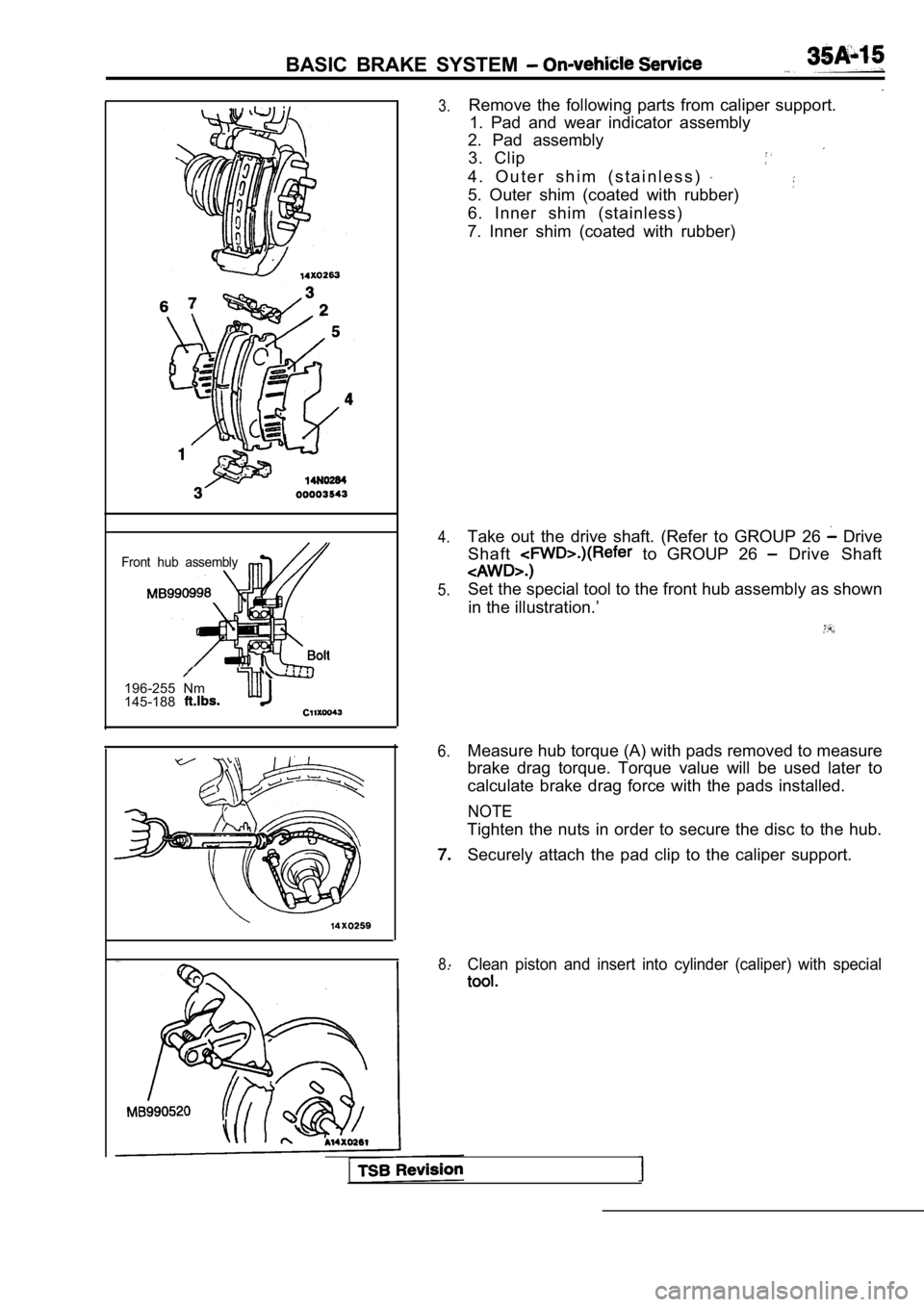
3.
4.
5.
6.
8.
Remove the following parts from caliper support. 1. Pad and wear indicator assembly
2. Pad assembly
3. Clip
4 . O u t e r s h i m ( s t a i n l e s s )
5. Outer shim (coated with rubber)
6. Inner shim (stainless)
7. Inner shim (coated with rubber)
Take out the drive shaft. (Refer to GROUP 26
Drive
Shaft
to GROUP 26 Drive Shaft
Set the special tool to the front hub assembly as s hown
in the illustration.’
Measure hub torque (A) with pads removed to measure
brake drag torque. Torque value will be used later to
calculate brake drag force with the pads installed.
NOTE
Tighten the nuts in order to secure the disc to the hub.
Securely attach the pad clip to the caliper support .
Clean piston and insert into cylinder (caliper) with special
Page 1659 of 2103
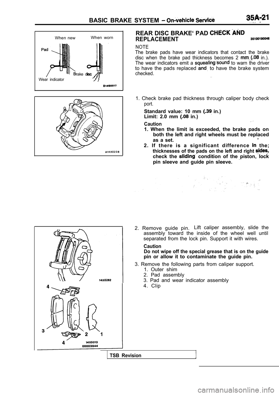
BASIC BRAKE SYSTEM
When newWhen worn
rake disc
Wear indicator
1 REAR DISC BRAKE‘ PAD
REPLACEMENT
NOTE
The brake pads have wear indicators that contact th
e brake
disc when the brake pad thickness becomes 2
in.).
The wear indicators emit a
to warn the driver
to have the pads replaced to have the brake system
checked.. .
1. Check brake pad thickness through caliper body c heck
port.
Standard value: 10 mm in.)
Limit: 2.0 mm
in.)
Caution
1. When the limit is exceeded, the brake pads on
both the left and right wheels must be replaced
as a set. ,
2 . I f t h e r e i s a s i g n i f i c a n t d i f f e r e n c e
the;
thicknesses of the pads on the left and right
check the condition of the piston, lock
pin sleeve and guide pin sleeve.
2. Remove guide pin. Lift caliper assembly, slide the
assembly toward the inside of the wheel well until
separated from the lock pin. Support it with wires.
Caution Do not wipe off the special grease that is on the g uide
pin or allow it to contaminate the guide pin.
3. Remove the following parts from caliper support. 1. Outer shim
2. Pad assembly
3. Pad and wear indicator assembly
4. Clip
TSB Revision
Page 1660 of 2103
BASIC BRAKE SYSTEM On-vehicle Service
TSB Revision
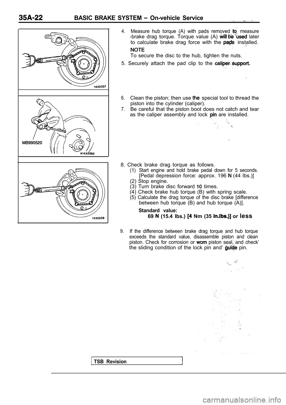
4.Measure hub torque (A) with pads removed measure
-brake drag torque. Torque value (A) later
to calculate brake drag force with the
installed.
To secure the disc to the hub, tighten the nuts.
5. Securely attach the pad clip to the
6.Clean the piston; then use special tool to thread the
piston into the cylinder (caliper).
7.Be careful that the piston boot does not catch and tear
as the caliper assembly and lock
are installed.
8. Check brake drag torque as follows.
(1) Start engine and hold brake pedal down for 5 second
s.
[Pedal depression force: approx. 196 (44 Ibs.)]
(2) Stop engine.
(3) Turn brake disc forward
times.
(4) Check brake hub torque (B) with spring scale.
(5) Calculate the drag torque of the disc brake [di fference
between hub torque (B) and hub torque (A)].
Standard value:
69 (15.4 Ibs.) Nm (35 or less
9.If the difference between brake drag torque and hub torque
exceeds the standard value, disassemble piston and clean
piston. Check for corrosion or piston seal, and check’
the sliding condition of the lock pin and’ pin.