1990 MITSUBISHI SPYDER wiring
[x] Cancel search: wiringPage 8 of 2103
G E N E R A L How to Use Troubleshooting/Inspection Service Points
Troubleshooting of electronic control systems for which the scan tool the basic outline
described below. Furthermore, even in systems for w hich the scan tool cannot be used, part of these
systems still follow this outline.
TROUBLESHOOTING CONTENTS
1. STANDARD FLOW OF DIAGNOSTIC TROUBLESHOOTING
The main procedures for diagnostic troubleshooting are shown.
2. SYSTEM OPERATION AND SYMPTOM VERIFICATION TESTS If verification of the trouble symptoms is difficul t, procedures for checking operation and verifying
trouble symptoms are shown.
3. DIAGNOSTIC FUNCTION The following diagnostic functions are shown.
l ,Method of reading diagnostic trouble codes
Method of erasing diagnostic trouble codes
lInput inspection service points
4. INSPECTION CHART FOR DIAGNOSTIC TROUBLE CODES
5. INSPECTION PROCEDURE FOR DIAGNOSTIC TROUBLE CODE S
Indicates the inspection procedures corresponding t o each diagnostic trouble code. (Refer to the
next page on how to use the inspection procedures.)
6. INSPECTION CHART FOR TROUBLE SYMPTOMS
If there are trouble symptoms, even though the scan tool displays no diagnostic inspection
procedures for each trouble symptom will be found b y means of this chart.
7. INSPECTION PROCEDURE FOR TROUBLE SYMPTOMS
Indicates the inspection procedures corresponding t o each trouble symptoms the Inspection
Chart for Trouble Symptoms. (Refer to the next page on how to use the inspection procedures.)
8. DATA LIST REFERENCE TABLE
Inspection items and normal judgement values have b een provided in this chart as reference
9. CHECK AT ECU TERMINALS
Terminal numbers for the ECU connectors, inspection items and standard values have been provided
in this chart as reference information.
Terminal Voltage Checks
1. Connect a needle-nosed wire probe or paper clip to a voltmeter probe.
2.Insert the needle-nosed wire probe into each of the ECU connector from the wire side,
and measure the voltage while referring to the chec k chart.
NOTE
1. Measure voltage with the ECU connectors connecte d.
2. You may find it convenient to pull out the ECU t o make it easier to reach the connector
terminals.
3. Checks don’t have to be carried out in the order given in the chart.
Short-circuiting the positive probe between a connector damage
the vehicle wiring, the sensor, the ECU, or all thr ee.
Use care to prevent this
3. If voltage readings differ from Normal Condition values, related actuators, and
wiring, then replace or repair.
TSB Revision
Page 9 of 2103
GENERAL How to Use Troubleshooting/Inspection Service Points
4.After repair or replacement, recheck the voltmeter to confirm the repair
the problem.
Terminal Resistance and Continuity Checks
1. Turn the ignition switch to off.
2. Disconnect the ECU connector.
3.Measure the resistance and check for continuity bet ween the terminals of the ECU
connector while referring to the check chart.
NOTE
Checks don’t have to be carried out in the order gi ven in the chart.
Cautlon
If resistance and continuity checks are performed the wrong terminals, damage
vehicle wiring, sensors, ECU, and/or ohmmeter may o ccur.
Use care to prevent this!
4.If the ohmmeter shows any deviation from the Normal Condition value, check the corresponding
5.
sensor, actuator and related electrical wiring, then repair or replace.
After repair or replacement, recheck with the ohmme ter to confirm that the repair
the problem.
10. INSPECTION PROCEDURES USING AN OSCILLOSCOPE
When there are inspection procedures using an oscil loscope, these are listed here.
,
TSB Revision
Page 13 of 2103
G E N E R A L How to Use __
HOW TO COPE WITH INTERMITTENT
Most intermittent malfunctions occur under certain conditions. If those conditions can be identified, the
cause will be easier to find.
TO COPE WITH INTERMITTENT MALFUNCTION;1. Ask the customer about the malfunction
Ask what it feels
it sounds like, etc.
Then ask about
conditions; weather,
frequency of occurrence, and so on.
2.Determine the from the custom-
er’s responses
Typically, almost all intermittent malfunctions
occur from conditions like vibration, tempera-
ture and/or moisture change, poor connections.
From the customer’s replies, it should be rea-
soned which condition is influenced.
3. Use simulation test In the cases of vibration or poor connections,
use the simulation tests below to attempt to
duplicate the customer’s complaint. Determine
the most likely circuit(s) and perform
tion tests on the connectors and parts of that
circuit(s). Be sure to use the inspection proce-
dures provided for trouble codes
a n d t r o u b l e s y m p t o m s .
For temperature and/or moisture conditions re-
lated intermittent malfunctions, using common
sense, try to change the of
circuit components, then use
tion tests below,
4. Verify the intermittent malfunction is elimi-
nated
Repair the malfunctioning part and try to
the condition(s) again to verify the intermit-
tent malfunction has been eliminated.
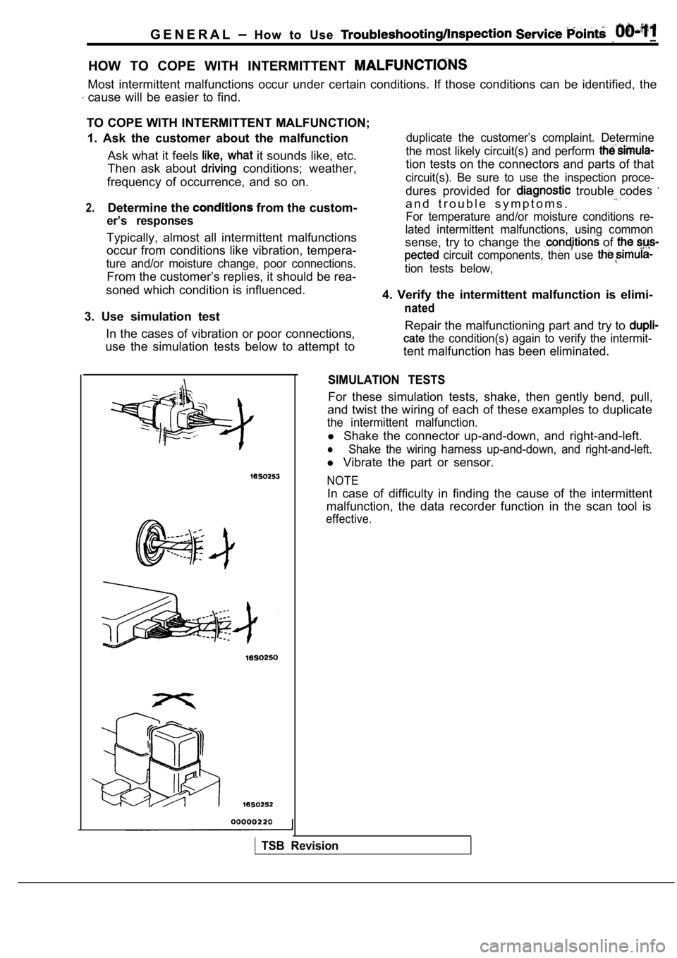
SIMULATION TESTS
For these simulation tests, shake, then gently bend , pull,
and twist the wiring of each of these examples to d uplicate
the intermittent malfunction.
l Shake the connector up-and-down, and right-and-left .
lShake the wiring harness up-and-down, and right-and -left.
l Vibrate the part or sensor.
NOTE
In case of difficulty in finding the cause of the i ntermittent
malfunction, the data recorder function in the scan tool is
effective.
TSB Revision
Page 22 of 2103
GENERAL before Service
PRECAUTIONS BEFORE SERVICE.
SUPPLEMENTAL RESTRAINT SYSTEM
1. to follow when servicing SRS
(1) Be sure to read GROUP Supplemental Restraint System
For safe operations, please follow the directions a nd heed all
(2) Always use the designated special tools and tes t equipment.
(3) Wait at least 60 seconds after disconnecting the battery cable before” further work;
The SRS system is designed to retain enough voltage to deploy the air bag even after the battery
has been disconnected. Serious injury may result from unintended air bag deployment if work
is done on the SRS system immediately after the bat tery cable is disconnected.
(4) Never attempt to disassemble or repair the SRS components (SRS-ECU air bag module and
clock spring). If faulty, replace it.
(5) Warning labels must be heeded when servicing or handling SRS components. Warning labels
are located in the following locations.
Sun visor
l Glove box
. S R S - E C U
l Steering wheel
l Air bag module
l Clock spring
l Steering gear and linkage clamp
(6) Store components removed from the SRS
a clean and dry place.
The air bag module should be stored on a flat surfa ce and placed so that the pad surface is’
facing upward.
Do not place anything on top of it.
(7) Be sure to deploy the air bag before disposing of the air bag’module or disposing of a vehicle
equipped with an air bag. (Refer to GROUP
Air Bag Module Disposal Procedures.)
(8) Whenever you finish servicing the
check the SRS warning light operation to make sure
that the system functions properly.
2.Observe the following when carrying out operations on places where SRS components are installed,’
.,
including operations not directly related to the SR S air bag.
(1) When removing or installing parts do not allow any impact or shock to the SRS components.
(2) SRS components should not be subjected to heat over so remove the SRS compo-
nents before drying or baking the vehicle after painting.
After re-installing them, check the SRS warning lig ht operation to make sure that the system
functions properly.
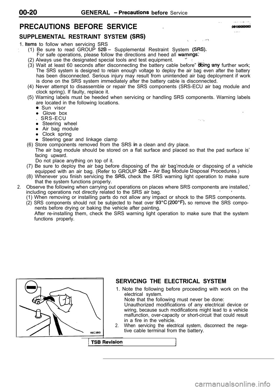
SERVICING THE ELECTRICAL SYSTEM
1. Note the following before proceeding with work o n the
electrical system.
Note that the following must never be done:
Unauthorized modifications of any electrical device or
wiring, because such modifications might lead to a vehicle
malfunction, over-capacity or short-circuit that co uld result
in a fire in the vehicle.
2.When servicing the electrical system, disconnect th e nega-
tive cable terminal from the battery.
Page 53 of 2103
GENERAL Maintenance
21 SYSTEM component
damage, to wiring,
harness, etc.)
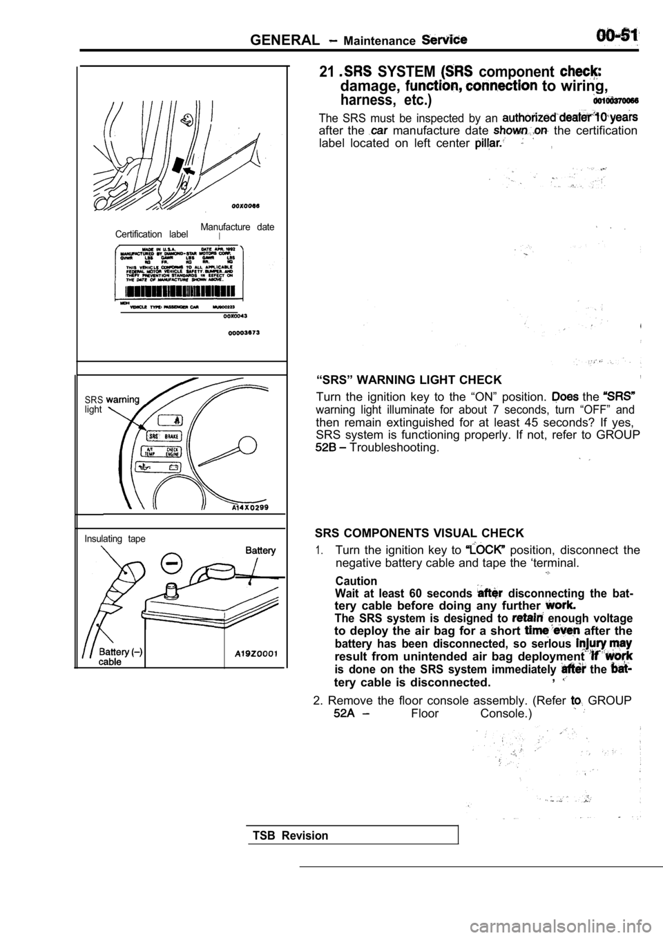
Certification labelManufacture dateI
SRSlight
Insulating tape
The SRS must be inspected by an
after the manufacture date the certification
label located on left center
,
“SRS” WARNING LIGHT CHECK,
Turn the ignition key to the “ON” position. the
warning light illuminate for about 7 seconds, turn “OFF” and
then remain extinguished for at least 45 seconds? I f yes,
SRS system is functioning properly. If not, refer t o GROUP
Troubleshooting.
SRS COMPONENTS VISUAL CHECK
1.Turn the ignition key to position, disconnect the
negative battery cable and tape the ‘terminal.
Caution
Wait at least 60 seconds
disconnecting the bat-
tery cable before doing any further
The SRS system is designed to enough voltage
to deploy the air bag for a short after the
battery has been disconnected, so serlous
result from unintended air bag deployment
is done on the SRS system immediately the
tery cable is disconnected. ,
2. Remove the floor console assembly. (Refer GROUP
Floor Console.)
TSB Revision
Page 55 of 2103
G E N E R A L Maintenance
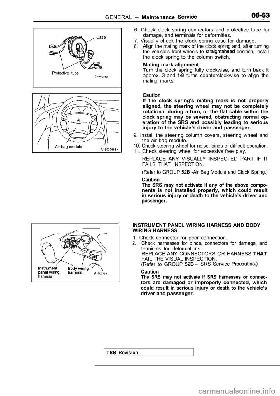
Protective tube
harness
6. Check clock spring connectors and protective tube for
damage, and terminals for deformities.
7. Visually check the clock spring case for damage.
8.Align the mating mark of the clock spring and, afte r turning
the vehicle’s front wheels to
position, install
the clock spring to the column switch.
Mating mark alignment
Turn the clock spring fully clockwise, and turn bac k it
approx. 3 and
turns counterclockwise to align the
mating marks.
Caution
If the clock spring’s mating mark is not properly
aligned, the steering wheel may not be completely
rotational during a turn, or the flat cable within the
clock spring may be severed, obstructing normal op-
eration of the SRS and possibly leading to serious
injury to the vehicle’s driver and passenger.
9. Install the steering column covers, steering whe el and
the air bag module.
10. Check steering wheel for noise, binds of diffic ult operation.
11. Check steering wheel for excessive free play.
REPLACE ANY VISUALLY INSPECTED PART IF IT
FAILS THAT INSPECTION.
(Refer to GROUP
-Air Bag Module and Clock Spring.)
Caution
The SRS may not activate if any of the above compo-
nents is not installed properly, could result
in serious injury or death to the vehicle’s driver and
passenger.
INSTRUMENT PANEL WIRING HARNESS AND BODY
WIRING HARNESS
1. Check connector for poor connection.
2.Check harnesses for binds, connectors for damage, a nd
terminals for deformations.
REPLACE ANY CONNECTORS OR HARNESS THAT
FAIL THE VISUAL INSPECTION.
(Refer to GROUP
SRS Service
Caution
The SRS may not activate if SRS harnesses or connec -
tors are damaged or improperly connected, which
could result in serious injury or death to the vehicle’s
driver and passenger.
Revision
Page 77 of 2103
ENGINE Engine Assembly
4.9
29
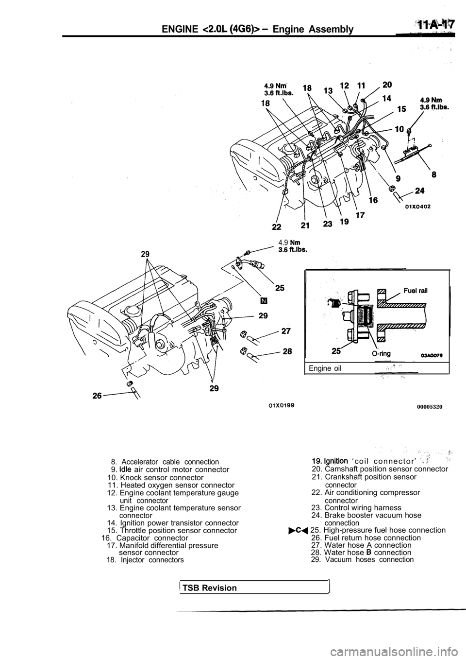
8. Accelerator cable connection9. air control motor connector
10. Knock sensor connector 11. Heated oxygen sensor connector
12. Engine coolant temperature gauge
unit connector13. Engine coolant temperature sensorconnector
Engine oil
00005320
‘ c o i l c o n n e c t o r ’ 20. Camshaft position sensor connector
21. Crankshaft position sensor
connector22. Air conditioning compressor
connector23. Control wiring harness 24. Brake booster vacuum hose .
14. Ignition power transistor connector
15. Throttle position sensor connector
16. Capacitor connector 17. Manifold differential pressure sensor connector
18. Injector connectors connection
25. High-pressure fuel hose connection
26. Fuel return hose connection
27. Water hose A connection
28. Water hose
connection29. Vacuum hoses connection
TSB Revision
Page 91 of 2103
ENGINE Cylinder Head
CYLINDER HEAD GASKET
REMOVAL AND INSTALLATION
Pre-removal Operationl Fuel Line Inner Pressure Release(Refer to GROUP On-vehiclel Engine Coolant Draining(Refer to GROUP 00 Maintenance Service.)l Engine Oil Draining(Refer to GROUP 00 Maintenance Service.)
3.62.9 Nm
2.2
4.9 Nm
220 1
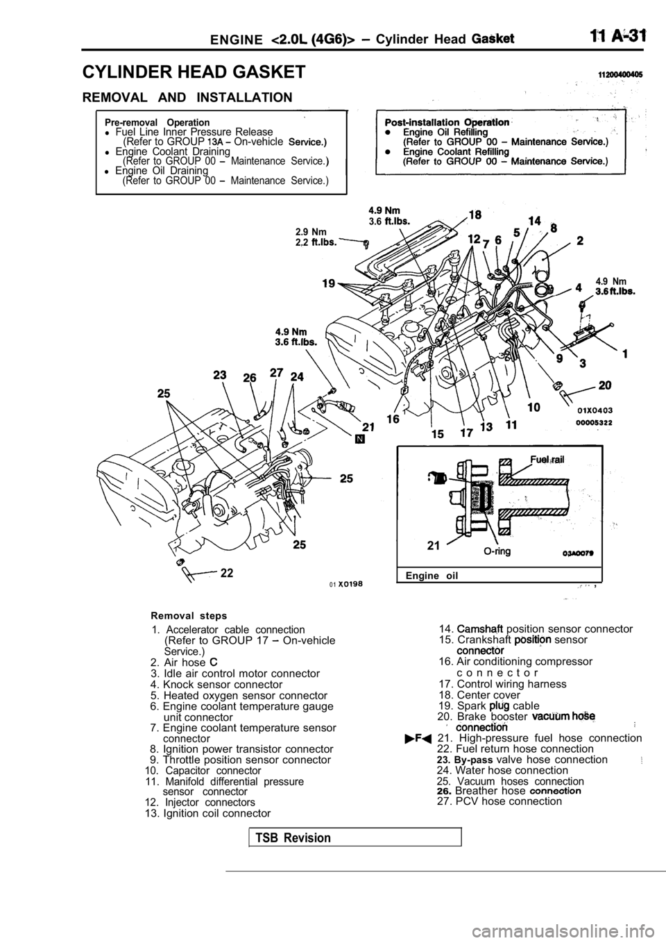
Removal steps
1. Accelerator cable connection(Refer to GROUP 17 On-vehicleService.)2. Air hose 3. Idle air control motor connector
4. Knock sensor connector
5. Heated oxygen sensor connector
6. Engine coolant temperature gauge
unit connector
7. Engine coolant temperature sensor
connector8. Ignition power transistor connector
9. Throttle position sensor connector
10. Capacitor connector
11. Manifold differential pressure sensor connector
12. Injector connectors
13. Ignition coil connector Engine oil
,
21
14. position sensor connector
15. Crankshaft sensor
16. Air conditioning compressor
c o n n e c t o r
17. Control wiring harness
18. Center cover
19. Spark
cable
20. Brake booster
21. High-pressure fuel hose connection 22. Fuel return hose connection
23. By-pass valve hose connection
24. Water hose connection25. Vacuum hoses connection26.Breather hose 27. PCV hose connection
TSB Revision