Page 2036 of 2103

SRS Air Bag Module Disposal,. Procedures
AIR BAG MODULE DISPOSAL PROCEDURES 52499120999
Before either disposing of a vehicle equipped with
an air bag, or prior to disposing of the air bag ule, be sure to first follow the procedures describ ed
below to deploy the air bag.
A I R
Caution
1.If the vehicle is to be scrapped, or otherwise disp osed
of, deploy the air bag inside the vehicle. If the v ehicle
will continue to be operated and only the air bag m od-
ule is to be disposed of, deploy the air bag outside
the vehicle.
2. Since a large amount of smoke is produced when the air bag is deployed, select a well-ventilated s ite.
Moreover, never attempt the test near a smoke senso r.
3. Since there is a loud noise when the air bag is
deployed, avoid
areas whenever possible.
If anyone is nearby, give warning of the impending
noise.
4.Suitable ear protection be worn by personnel
performing these procedures or by people in the im-
mediate area.
DEPLOYMENT INSIDE THE VEHICLE
(when disposing of a vehicle)
(1) Open all windows and doors of. the vehicle. Mov e the
vehicle to an isolated spot.
(2)Disconnect the negative and positive battery cables
from the battery terminals, and then remove the bat tery
from the vehicle.
Caution
Wait at least 60 seconds after disconnecting the
tery cables before doing any further work.
(Refer to
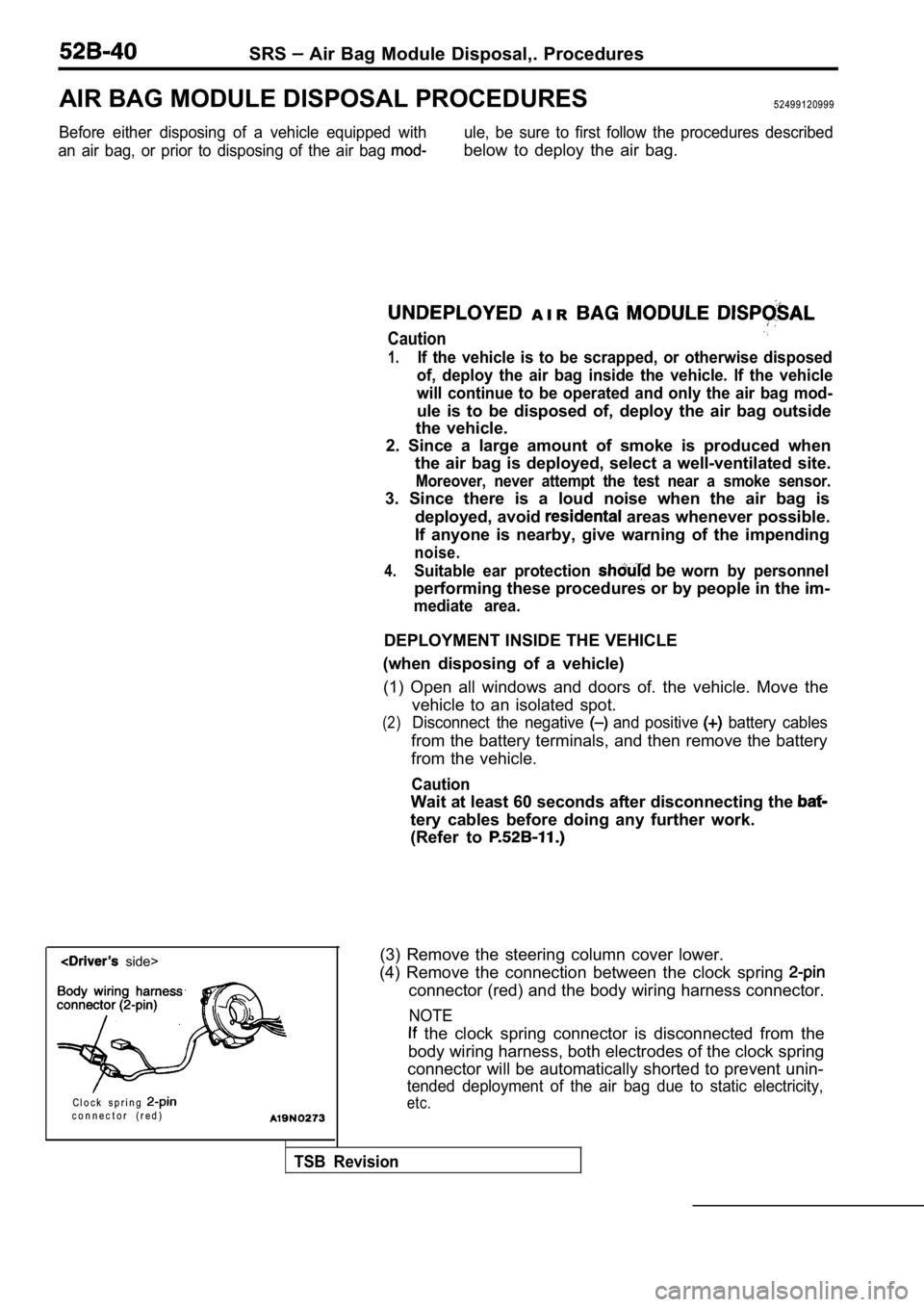
side>
C l o c k s p r i n g
c o n n e c t o r ( r e d )
(3) Remove the steering column cover lower.
(4) Remove the connection between the clock spring
connector (red) and the body wiring harness connect or.
NOTE
the clock spring connector is disconnected from th e
body wiring harness, both electrodes of the clock s pring
connector will be automatically shorted to prevent unin-
tended deployment of the air bag due to static elec tricity,
etc.
TSB Revision
Page 2037 of 2103

SRS Air Baa Module Disposal
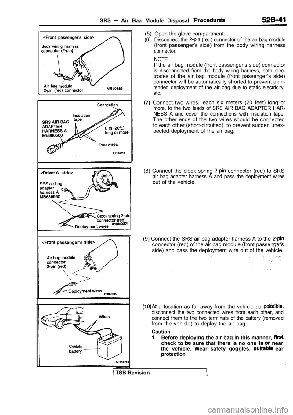
Body wiring harness
Air bag (red) connector
Connection
Insulation
side>
passenger’s
TSB Revision (5). Open the glove compartment.
(6)Disconnect the (red) connector of the air bag module
(front passenger’s side) from the body wiring harne
ss
connector.
NOTE
If the air bag module (front passenger’s side) connector
is disconnected from the body wiring harness, both elec-
trodes of the air bag module (front passenger’s side)
connector will be automatically shorted to prevent unin-
tended deployment of the air bag due to static elec tricity,
etc.
Connect two wires,each six meters (20 feet) long or
more, to the two leads of SRS AIR BAG ADAPTER HAR-
NESS A and cover the connections with insulation ta pe.
The other ends of the two wires should be connected
to each other (short-circuited), to prevent sudden unex-
pected deployment of the air bag.
(8) Connect the clock spring
connector (red) to SRS
air bag adapter harness A and pass the deployment w ires
out of the vehicle.
(9) Connect the SRS air bag adapter harness A to th e
connector (red) of the air bag module (front passengers
side) and pass the deployment wire out of the vehic le.
a location as far away from the vehicle as
disconnect the two connected wires from each other, and
connect them to the two terminals of the battery (r emoved
from the vehicle) to deploy the air bag.
Caution
1.Before deploying the air bag in this manner,
check to sure that there is no one near
the vehicle. Wear safety goggles,
ear
protection.
Page 2041 of 2103

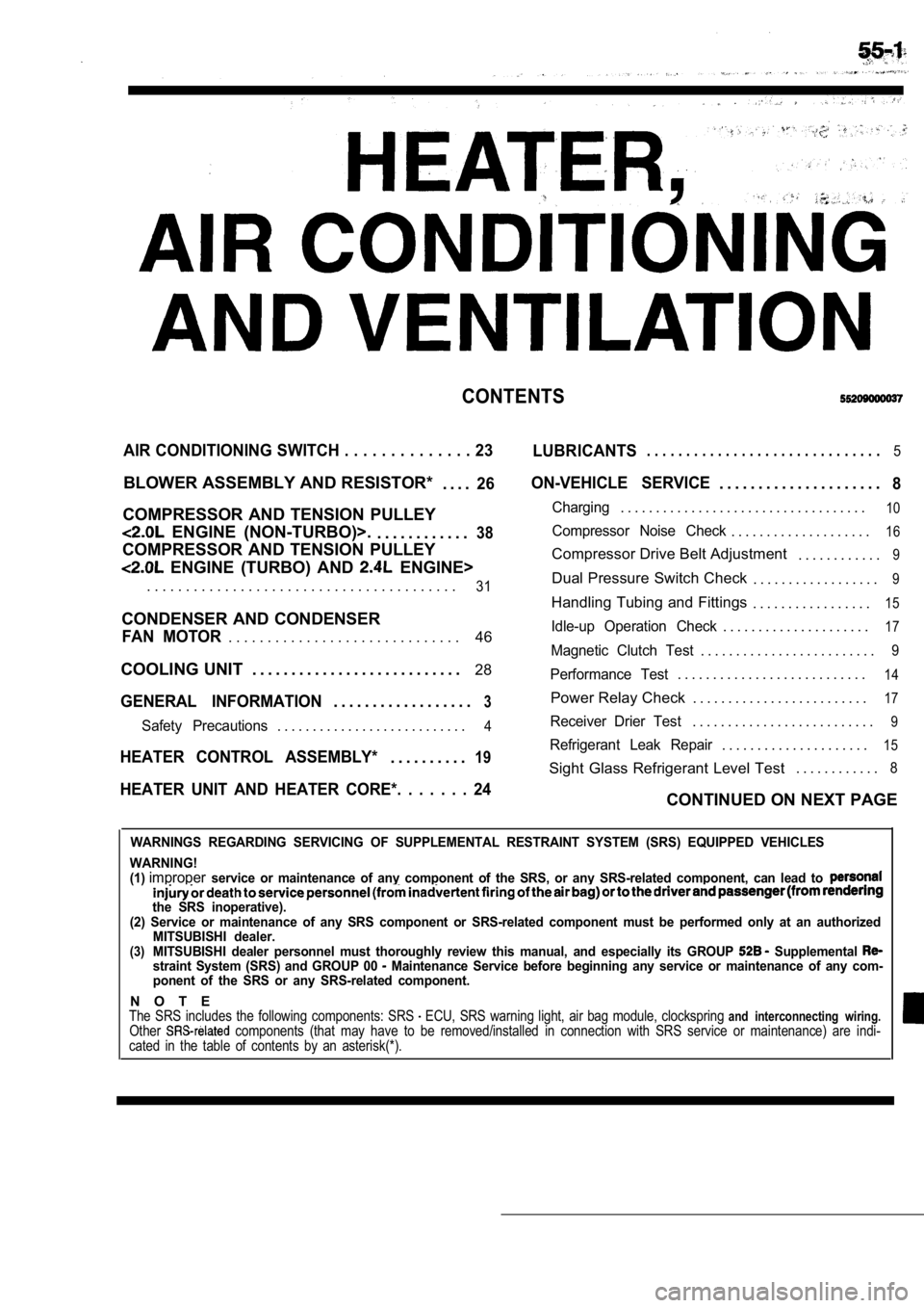
CONTENTS
AIR CONDITIONING SWITCH . . . . . . . . . . . . . . 23
LUBRICANTS. . . . . . . . . . . . . . . . . . . . . . . . . . . . . .5
BLOWER ASSEMBLY AND RESISTOR*
. . . .26
COMPRESSOR AND TENSION PULLEY
ENGINE (NON-TURBO)>.. . . . . . . . . . . .38
COMPRESSOR AND TENSION PULLEY
ENGINE (TURBO) AND ENGINE>
ON-VEHICLE SERVICE. . . . . . . . . . . . . . . . . . . . .8
Charging. . . . . . . . . . . . . . . . . . . . . . . . . . . . . . . . . . .10
Compressor Noise Check. . . . . . . . . . . . . . . . . . . .16
Compressor Drive Belt Adjustment . . . . . . . . . . . .9
. . . . . . . . . . . . . . . . . . . . . . . . . . . . . . . . . . . . . . . .31Dual Pressure Switch Check. . . . . . . . . . . . . . . . . .9
Handling Tubing and Fittings. . . . . . . . . . . . . . . . .15
CONDENSER AND CONDENSER
46Idle-up Operation Check. . . . . . . . . . . . . . . . . . . . .17FAN MOTOR. . . . . . . . . . . . . . . . . . . . . . . . . . . . . .Magnetic Clutch Test. . . . . . . . . . . . . . . . . . . . . . . . .9
COOLING UNIT . . . . . . . . . . . . . . . . . . . . . . . . . . . 28
GENERAL INFORMATION3. . . . . . . . . . . . . . . . . .
Performance Test. . . . . . . . . . . . . . . . . . . . . . . . . . .14
Power Relay Check . . . . . . . . . . . . . . . . . . . . . . . . .17
Safety Precautions. . . . . . . . . . . . . . . . . . . . . . . . . . .4Receiver Drier Test. . . . . . . . . . . . . . . . . . . . . . . . . .9
. . . . . . . . . . . . . . . . . . . . .15HEATER CONTROL ASSEMBLY*19Refrigerant Leak Repair. . . . . . . . . .
Sight Glass Refrigerant Level Test . . . . . . . . . . . .8
HEATER UNIT AND HEATER CORE*. . . . . . . 24CONTINUED ON NEXT PAGE
WARNINGS REGARDING SERVICING OF SUPPLEMENTAL RESTRA
INT SYSTEM (SRS) EQUIPPED VEHICLES
WARNING!
(1)
improperservice or maintenance of any component of the SRS, or any SRS-related component, can lead to
the SRS inoperative).
(2) Service or maintenance of any SRS component or SRS-related component must be performed only at an authorized
MITSUBISHI dealer.
(3)MITSUBISHI dealer personnel must thoroughly review this manual, and especially its GROUP Supplemental straint System (SRS) and GROUP 00 Maintenance Service before beginning any service or maintenance of any com-
ponent of the SRS or any SRS-related component.
N O T EThe SRS includes the following components: SRS ECU, SRS warning light, air bag module, clocksprin g and interconnecting wiring.Other components (that may have to be removed/installed in connection with SRS service or maintenance) are indi-
cated in the table of contents by an asterisk(*).