Page 625 of 2103
ENGINE (TURBO)
AND Troubleshooting ,
CHECK AT THE ENGINE
TERMINAL VOLTAGE CHECK CHART1. Connect a needle-nosed wire probe (paper
etc.) to
a
probe.
2.insert the needle-nosed wire probe into each of the ECM
connector terminals from the wire side, and measure the
voltage referring to the check chart.
NOTE
1.Measure voltage with the ECM connectors connected.
2. You may find it convenient to pull out the ECM to
make it easier to reach the connector terminals.’
3.Checks don’t have to be carried out in the order gi ven
in the chart.
Caution
Short-circuiting the positive
probe between a con-
nector terminal and ground
vehicle
wiring, the sensor, ECM, or all three. Use care to pre-
vent this!
3.If voltmeter division from standard value, check
the corresponding sensor, actuator and related elec trical
wiring, then repair or replace.
4. After repair or replacement,, recheck with the v oltmeter
to confirm that the repair has corrected the proble m.
TSB Revision
Page 631 of 2103

ENGINE (TURBO)
AND ENGINE>
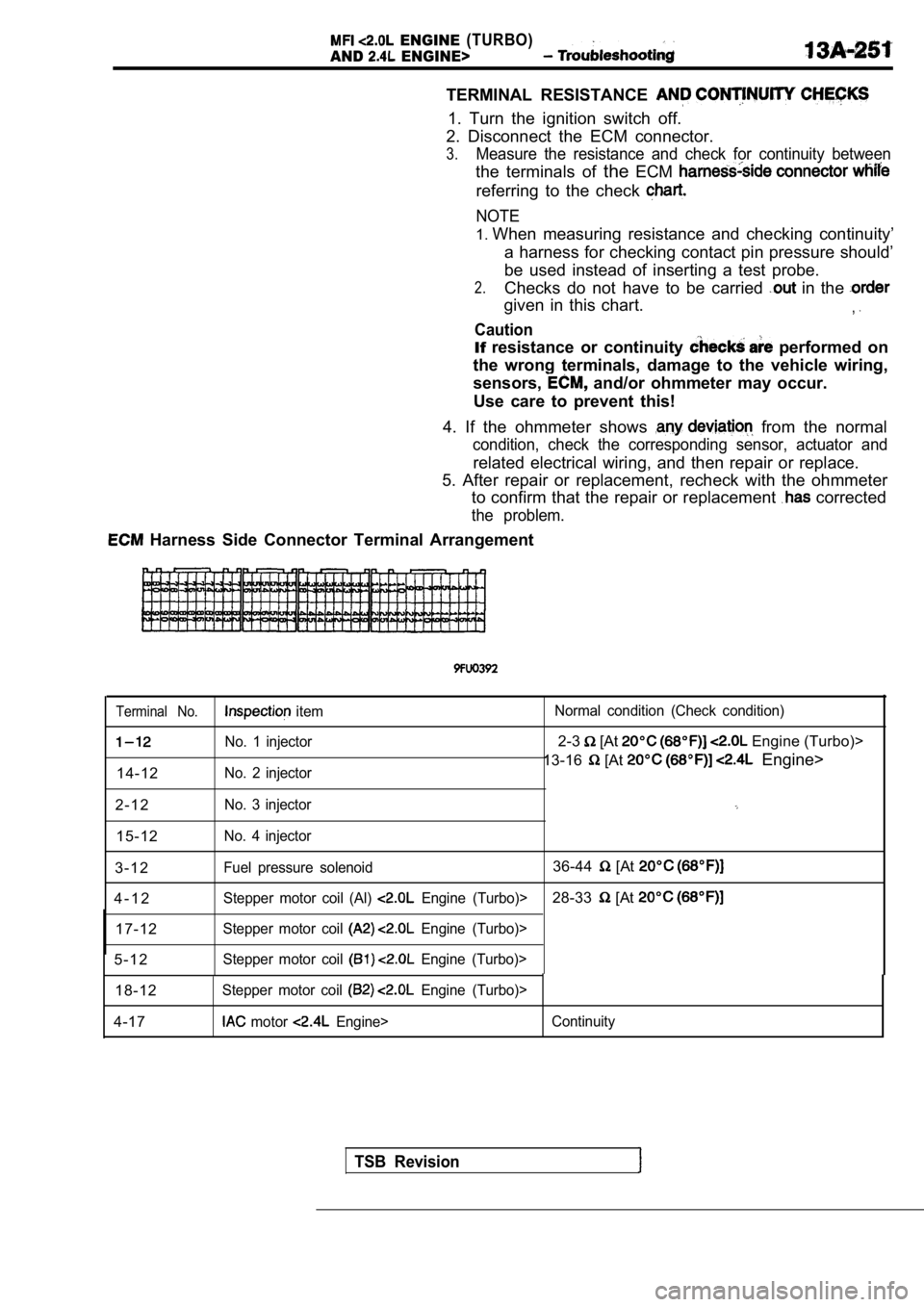
TERMINAL RESISTANCE
1. Turn the ignition switch off.
2. Disconnect the ECM connector.
3.Measure the resistance and check for continuity bet ween
the terminals of theECM
referring to the check
NOTE
1.When measuring resistance and checking continuity’
a harness for checking contact pin pressure should’
be used instead of inserting a test probe.
2.Checks do not have to be carried in the
given in this chart.,
Caution
If resistance or continuity performed on
the wrong terminals, damage to the vehicle wiring,
sensors,
and/or ohmmeter may occur.
Use care to prevent this!
4. If the ohmmeter shows
from the normal
condition, check the corresponding sensor, actuator and
related electrical wiring, and then repair or replace.
5. After repair or replacement, recheck with the oh mmeter
to confirm that the repair or replacement
corrected
the problem.
Harness Side Connector Terminal Arrangement
Terminal No. item Normal condition (Check condition)
No. 1 injector2-3 [At Engine (Turbo)>
No. 2 injector13-16 [At Engine>
14-12
2 - 1 2
No. 3 injector
15-12No. 4 injector
3 - 1 2Fuel pressure solenoid36-44 [At
4 - 1 2Stepper motor coil (Al) Engine (Turbo)>28-33 [At
17-12Stepper motor coil Engine (Turbo)>
5 - 1 2Stepper motor coil Engine (Turbo)>
18-12Stepper motor coil Engine (Turbo)>
4-17 motor Engine> Continuity
TSB Revision
Page 710 of 2103
Water: Hose and Water Pipe EngineE N G I N E C O O L I N G ( N o n - t u r b o ) >
WATER HOSE AND WATER PIPE
~ 4 1 0 0 5 5 0 1 1 5
REMOVAL AND INSTALLATION
Pre-removal and Post-installation OperationlEngine Coolant Draining and Supplying (Refer toGROUP 00 Service.)lUnder Cover Removal and Installation (Refer to
GROUP 42 Under Cover.)I I
3.92.9
7
33
Removal steps
1. Air intake hose
2. Air hose connection 7. Radiator fan motor assembly
8. Radiator lower hose connection
3. Control wiring harness connection
4. Water pipe assembly
5. Water hose6. Heater hose connection
9. Water hose10. Front exhaust pipe connection Water inlet pipe assembly 12. O-ring
TSB Revision
Page 721 of 2103
INTAKE AND EXHAUST Intake Manifold Engine
REMOVAL AND INSTALLATION
Operationl Residual Fuel Pressure Releasing(Refer to GROUP Service.)l Engine Coolant Draining(Refer to GROUP Service.)l Reservoir Assembly Removal with Auto-Cruise
2.9
Post-installation Operationl Reservoir Assembly Installation
l Engine Coolant Supplying (Refer to GROUP Service.)l Accelerator Cable Adjustment (Refer to GROUP 17 On-vehicle Service.)
3.92 . 9
O-ring
Engineoil
Removalsteps
1. Air intake hose2.Breather hose
3. Accelerator cable connection
4. Clip5. MAP sensor connector
6. Charge temperature sensor connector
7. Vacuum hose connection
8.TPS connector9. motor connector 10.
wiring harness11. connection
12. PCV hose assembly 13. Vacuum hose connection14. Brake booster hose
connection
15. pipe connection
16. fuel hose connection
TSB Revision
Page 725 of 2103

INTAKE AND EXHAUST Intake Manifold Engine
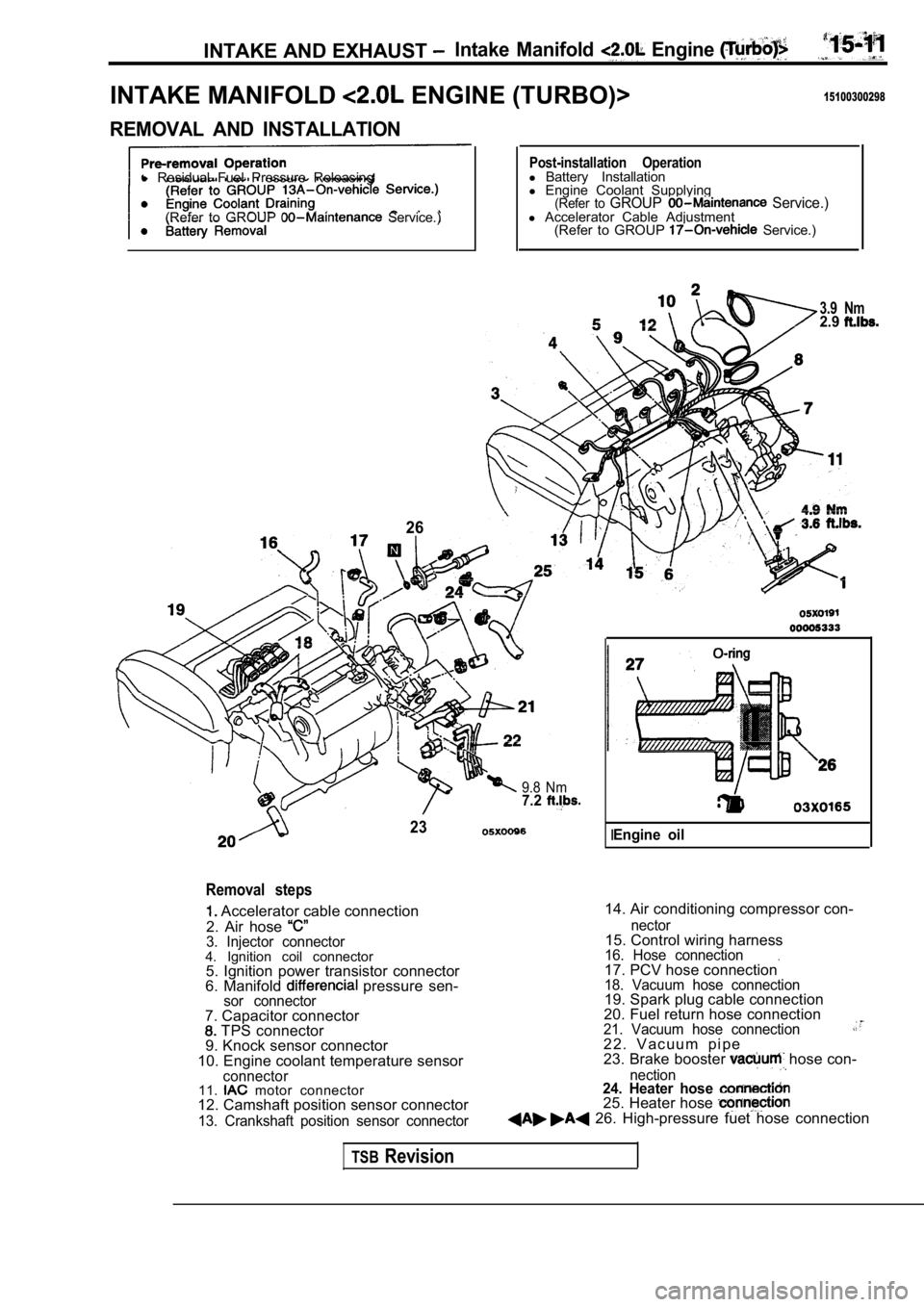
INTAKE MANIFOLD ENGINE (TURBO)>15100300298
REMOVAL AND INSTALLATION
l Residual Fuel Pressure Releasing
(Refer to GROUP
Service.)
26
Post-installation Operationl Battery Installation
l Engine Coolant Supplying
(Refer to GROUP Service.)l Accelerator Cable Adjustment
(Refer to GROUP Service.)
3.9 Nm2.9
9.8 Nm7.2
23
Removal steps
Accelerator cable connection
2. Air hose
3. Injector connector4. Ignition coil connector 5. Ignition power transistor connector
6. Manifold
pressure sen-sor connector
14. Air conditioning compressor con-
7. Capacitor connector
TPS connector
9. Knock sensor connector
10. Engine coolant temperature sensor
connector11. motor connector
12. Camshaft position sensor connector
13. Crankshaft position sensor connector nector
15. Control wiring harness16. Hose connection.17. PCV hose connection18. Vacuum hose connection19. Spark plug cable connection
20. Fuel return hose connection
21. Vacuum hose connection2 2 . V a c u u m p i p e
23. Brake booster hose con-
nection24. Heater hose 25. Heater hose 26. High-pressure fuet hose connection
IEngine oil
TSBRevision
Page 728 of 2103

INTAKE AND EXHAUST Intake Manifold
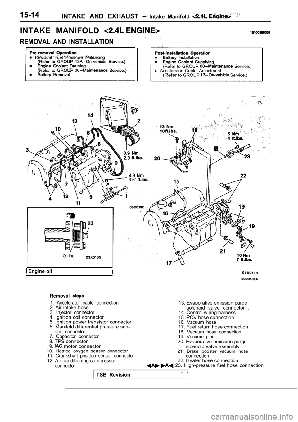
INTAKE MANIFOLD
REMOVAL AND INSTALLATION
l Residual Fuel Pressure Releasing
(Refer to GROUP
Service.) (Refer to GROUP Service.)
l Accelerator Cable Adjustment
(Refer to GROUP
Service.)
2.9
4.9 Nm 3.6’ 15
O-ring
Engine oilI
18
10 Nm7
Removal
1. Accelerator cable connection2. Air intake hose3. Injector connector4. Ignition coil connector
5. Ignition power transistor connector
6. Manifold differential pressure sen-
sor connector
7. Capacitor connector
8. TPS connector
9. motor connector
10. Heated oxygen sensor connector
11. Crankshaft position sensor connector12. Air conditioning compressor
connector
13. Evaporative emission purge
solenoid valve connector .
14. Control wiring harness
15. PCV hose connection
16. Vacuum hose17. Fuel return hose connection18. Vacuum hose connection
19. Vacuum pipe
20. Evaporative emission purge solenoid valve assembly
21. Brake booster vacuum hose
connection22. Heater hose connection 23. High-pressure fuel hose connection
TSB Revision
Page 731 of 2103
INTAKE, AND EXHAUST Exhaust Manifold Engine
EXHAUST MANIFOLD ENGINE (NON-TURBO)>’
REMOVAL AND INSTALLATION
and Post-installation Operationl Engine Coolant Draining and (Refer to GROUP
3.9 Nm2.9
6
Removal steps
1. Air intake hose
2. Radiator upper hose connection
3. Air hose connection
4. Control wiring harness connection
5. Water pipe assembly
6. Engine oil level gauge
Nm
44Nm33
,
7.Heat protector6.Engine hanger9. Front exhaust connection10.Heatprotector11. Exhaust 12. Exhaust manifold gasket
TSB RevisionI
Page 859 of 2103

CONTENTS
MANUAL TRANSAXLE ENGINEMANUAL TRANSAXLE ENGINE
(NON-TURBO)>(TURBO) AND ENGINE>
GENERAL INFORMATION . . . . . . . . . . . . . . 22GENERAL INFORMATION . . . . . . . . . . . . . . . .
2
LUBRICANTS. . . . . . . . . . . . . . . . . . . . . . . . . . 24LUBRICANTS. . . . . . . . . . . . . . . . . . . . . . . . . . .6
ON-VEHICLE SERVICE. . . . . . . . . . . . . . . . .
2 4
Transaxle Oil Level Check . . . . . . . . . . . . . . . .
24
Transaxle Oil Replacement . . . . . . . . . . . . . . .
24
SERVICE SPECIFICATIONS. . . . . . . . . . . . .24
SPECIAL TOOLS. . . . . . . . . . . . . . . . . . . . . . .24
TRANSAXLE ASSEMBLY. . . . . . . . . . . . . . .28
TRANSAXLE CONTROL*. . . . . . . . . . . . . . . .25ON-VEHICLE SERVICE
. . . . . . . . . . . . . . . . 8
Shift Lever Assembly
. . . . . . . . . . . . . . . . . . . . .
27
TROUBLESHOOTING. . . . . . . . . . . . . . . . . . .24
Transaxle Oil Level Check . . . . . . . . . . . . . . . . .8
Transaxle Oil Replacement
. . . . . . . . . . .. . .
Transfer Oil Level Check ...... . . . . . . . . . . .
Transfer Oil Replacement. . . . . . . . . . . . . . . . . .8
SERVICE SPECIFICATIONS. . . . . . . . . . ...
SPECIAL TOOLS 7. . . . . . . . . . . . . . . . . .
TRANSAXLE ASSEMBLY
. . . . . . . . . . . . . . . . . . . . ... . . .
. . . . . . . . . . . . . . . . . . . . . . . . . . . .
. . 1 2
TRANSAXLE CONTROL*... . . . . . . . .
Shift Lever Assembly. . . . . . . . . . . . . . . . . . . . . .1 1
TRANSFER ASSEMBLY . . . . . . . .
TROUBLESHOOTING . . . . . . . . . . . . . . . . . .
WARNINGS REGARDING SERVICING OF SUPPLEMENTAL RESTRA
INT SYSTEM (SRS) EQUIPPED VEHICLES
WARNING!
(1)Improper service or maintenance of any component of the or any component, can lead to personalinjury or death to service personnel (from inadvertent firing of the air bag) or to the driver and passenger (from
rendering the inoperative).Service or maintenance of any or component must be performed only at an authorized MITSUBISHI dealer.(3)MITSUBISHI dealer personnel must thoroughly review this manual,and especially its GROUP
Restraint System and GROUP 00 Maintenance Service, before beginning any or maintenance of
any component of the or any component.
NOTEThe SRS includes the following components: warning light, air bag module,clock spring, and interconnecting
wiring. Other
components (that may have to be removed/installed in connection with service or maintenance)
are indicated in the table of contents by an asterisk