1990 MITSUBISHI SPYDER wiring
[x] Cancel search: wiringPage 1738 of 2103
![MITSUBISHI SPYDER 1990 Service Repair Manual Code No. 15 Wheel sensor svstem
[Comment] of . This diagnostic trouble code is output when there is an abnormality (other than brokenwire or short circuit) in any of the MITSUBISHI SPYDER 1990 Service Repair Manual Code No. 15 Wheel sensor svstem
[Comment] of . This diagnostic trouble code is output when there is an abnormality (other than brokenwire or short circuit) in any of the](/manual-img/19/57345/w960_57345-1737.png)
Code No. 15 Wheel sensor svstem
[Comment] of . This diagnostic trouble code is output when there is an abnormality (other than brokenwire or short circuit) in any of the wheel speed sensor output signals while driving.l
Malfunction of harness
The following can be considered as the cause of the wheel speed sensor outputl
Malfunction of ABS rotor
l
wheel abnormality.l Malfunction of ABS-ECU
l Distortion of ABS rotor, teeth missing
l Low frequency noise interference when sensor harnes s is broken
l Noise interference in sensor signal
,lSensor output signal is below the standard value or amplitude modulation is over
the standard value. Using an oscilloscope to measur e the wave shape of the
wheel speed sensor output signal is very effective.
l Broken sensor harness
Poor connection of connector
I-NGWheel speed sensor insulation check Repair
(Refer to
OK
(Refer to(Refer to GROUP -Wheel Speed
Refer to 28 On-vehicleService.Refer to GROUP 27 On-vehicle wheel speed sensors and the
ABS-ECU. Repair, if necessary.
Check the following connector: l
OK
Check trouble symptom.
NG
the ABS-ECU.
Service.
NG Repair
,
Code No. 21 G-sensor systemProbable cause
[Comment]l Malfunction of G-sensor
The ABS-ECU outputs this diagnostic trouble code in the following cases.
l Malfunction of wiring harness or connector
lWhen there is an open or short circuit in the harne ss for the G-sensor system.
l Malfunction of ABS-ECU
G-sensor check (Refer to
Replace the G-sensor.
Measure at ABS-ECU connector
l Ignition switch ONlVoltage between terminal 8 and bodygroundOK 2.4-2.6 Check the harness between theOKCheck trouble symptom.G-sensor and the ABS-ECU. Repair,
NGif necessary.Check the following connector:
. Repair
OK
Check trouble symptom.
N G
Replace the ABS-ECU.
Page 1744 of 2103
ABS
Caution
1.If movements are made when driving at speed, or when driving on road
with low frictional resistance, or when passing over bumps, the ABS may
sudden braking is not being applied. of this, when getting
2.
check if the problem occurred while driving under s uch conditions
During ABS operation changes in the feeling of the brake pedal occur or
may not be able to be depressed). Such changes are due to in hydraulic
pressure inside the brake line to prevent, the whee ls from locking,
I N S P E C T I O N P R O C E D U R E F O R T R O U B L E S Y M P T O M S ,
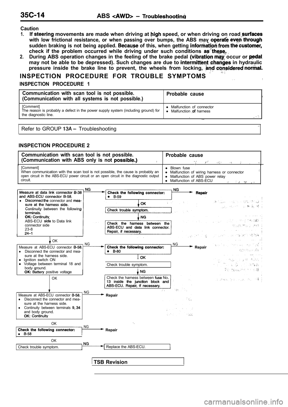
INSPECTION PROCEDURE 1
Communication with scan tool is not possible. Probable cause
(Communication with all systems is not possible.)
[Comment]l Malfunction of connector
The reason is probably a defect in the power supply system (including ground) for
the diagnostic line. l
Malfunction harness
Refer to GROUP Troubleshooting
INSPECTION PROCEDURE 2
Communication with scan tool is not possible.
(Communication with ABS only is not Probable cause
,
[Comment]l Blown fuse
When communication with the scan tool is not possib le, the cause is probably an
l Malfunction of wiring harness or connector
open circuit in the ABS-ECU power circuit or an ope n circuit in the diagnostic output
circuit.l Malfunction of ABS power relay
l Malfunction of ABS-ECU
,
l connector and
Continuity between the following
ABS-ECU
to Data link
connector side
23-8
OKNGMeasure at ABS-ECU connector lDisconnect the connector and mea-sure at the harness side.
N G Repair
l Ignition switch ON
l Voltage between terminal 18 and
bodv around. Check trouble symptom.
I positive voltage
OKCheck the harness between No
NG
Measure at ABS-ECU connector
lDisconnect the connector and mea-sure at the harness side.lContinuity between terminals and body ground.OK:
Repair
l
OKNG Repair
OK
Check trouble symptom. Replace the ABS-ECU.
TSB Revision
Page 1745 of 2103
![MITSUBISHI SPYDER 1990 Service Repair Manual ABS Troubleshooting
INSPECTION PROCEDURE 3
ignition key is turned to “ON’? (engine stopped),ProbableABS warning light does not illuminate
[Comment]When power is supplied to the ABS- MITSUBISHI SPYDER 1990 Service Repair Manual ABS Troubleshooting
INSPECTION PROCEDURE 3
ignition key is turned to “ON’? (engine stopped),ProbableABS warning light does not illuminate
[Comment]When power is supplied to the ABS-](/manual-img/19/57345/w960_57345-1744.png)
ABS Troubleshooting
INSPECTION PROCEDURE 3
ignition key is turned to “ON’? (engine stopped),ProbableABS warning light does not illuminate
[Comment]When power is supplied to the ABS-ECU, the valve relay changes from to OFF ON by the initial check, and thus even if there is a problem with the circuit betweenABS warning light and ABS-ECU, the light will illum inate once when the valve relayis OFF.Accordingly, the cause of the light not illuminating is probably an open circuit in the
light power circuit, a blown light bulb, or an open circuit in both the circuit between
the ABS
liaht and the ABS-ECU and the circuit between the ABS
l Blown fuselBurntout light. bulblMalfunction of wiring. or connector
.
light and the relay.When other lights also do not illuminate, the cause is probab ly a blown fuse.
N GNG ,
Measure at combination meter connector Checkl and l Disconnect the connector and mea-
l Disconnect the connector and mea-
sure atthe combination meter side.
l Continuitv between terminals
OK Continuity
OK
Not
Replace combination meter.
, Check the harnesses between the valve relay and the combination meter,
a n d b e t w e e n t h e A B S - E C U a n d
combination meter (common section).
Repair, if necessary.
INSPECTION PROCEDURE 4
Even after the engine is started, the ABS warning l ight Probable cause ,
remains illuminated.
[Comment]There is probably a short in the ABS light illumination l Malfunction of meter
l Malfunction of valve relay
l Malfunction of ABS-ECU
l Malfunction of wiring
NOTE
This trouble symptom is limited to cases where comm unication with the scan tool is
supply is normal) and the diagnostic trouble code is a normal diagnostic trouble code.
Disconnect the ABS-ECU connector Short circuit inside the combination meter or in the Does the ABS warning light remain illuminated? between the combination meter and the ABS-ECU.
NO
Replace the ABS-ECU.
TSB Revision
Page 1748 of 2103
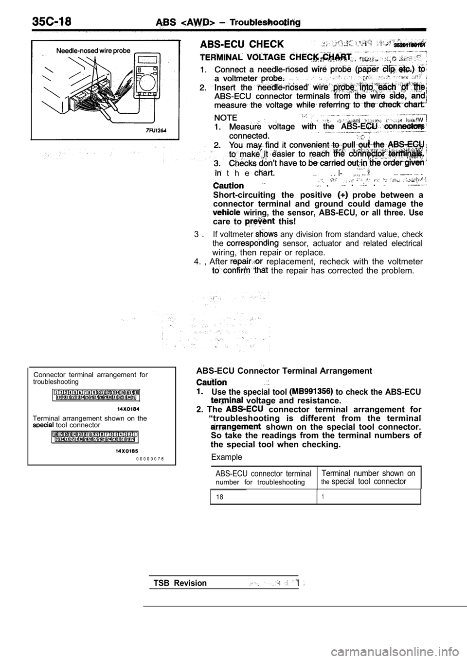
t h e . I-,..,
.. .
Short-circuiting the positive probe between a
connector terminal and ground could damage the
wiring, the sensor, ABS-ECU, or all three. Use
care to this!
3 .
If voltmeter any division from standard value, check
the
sensor, actuator and related electrical
wiring, then repair or replace.
4. , After
replacement, recheck with the voltmeter
the repair has corrected the problem.
Connector terminal arrangement for
troubleshooting
Terminal arrangement shown on the tool connector
0 0 0 0 0 0 7 6 ABS-ECU Connector Terminal Arrangement
Use the special tool to check the ABS-ECU
voltage and resistance.
2. The
connector terminal arrangement for
“troubleshooting is different from the terminal
shown on the special tool connector.
So take the readings from the terminal numbers of
the special tool when checking.
Example
ABS-ECU connector terminalTerminal number shown on
number for troubleshootingthespecial tool connector
181
TSB Revision
Page 1750 of 2103
ABS Troubleshooting
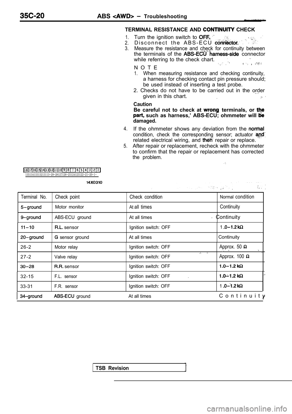
TERMINAL RESISTANCE AND
CHECK
7 13513413313213113~29~28127126~25124123122~21~20~1~
1.
2.
3.
4.
5.
Turn the ignition switch to
D i s c o n n e c t t h e A B S - E C U
Measure the resistance and check for continuity bet ween
the terminals of the connector
while referring to the check chart.
N O T E
,
1.When measuring resistance and checking continuity,
a harness for checking contact pin pressure should;
be used instead of inserting a test probe.
2. Checks do not have to be carried out in the orde r
given in this chart.
Caution
Be careful not to check at terminals, or
such as harness,’ ABS-ECU; ohmmeter will
damaged.
If the ohmmeter shows any deviation from the
condition, check the corresponding sensor; actuator
related electrical wiring, and repair or replace.
After repair or replacement, recheck with the ohmmeter
to confirm that the repair or replacement has corre cted
the problem.
Terminal No.Check point Check conditionNormalcondition
Motor monitorAtall timesContinuity
ABS-ECU ground At all times Continuity
sensor
sensor groundIgnition switch: OFF
1At all timesContinuity
2 6 - 2
Motor relay
2 7 - 2Valve relay
sensor
Ignition switch: OFF
Ignition switch: OFF
Ignition switch: OFFApprox. 50
Approx. 100
32-15F.L. sensor
33-31F.R. sensor
Ignition switch: OFF
Ignition switch: OFF.
1
ground At all timesC o n t i n u i t y
I’
TSB Revision
Page 1763 of 2103
CONTENTS
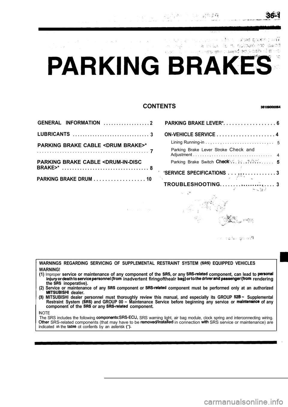
GENERAL INFORMATION. . . . . . . . . . . . . . . . . . 2PARKING BRAKE LEVER*. . . . . . . . . . . . . . . . . . 6
LUBRICANTS. . . . . . . . . . . . . . . . . . . . . . . . . . . . . . .3ON-VEHICLE SERVICE . . . . . . . . . . . . . . . . . . . . . 4
PARKING BRAKE CABLE
. . . . . . . . , . .5
7Parking Brake Lever Stroke
Check and. . . . . . . . . . . . . . . . . . . . . . . . . . . . . . . . . . . . . . . . . . . .Adjustment . . . . . . . , . . . . . . . . . . . . . . . . . . . . . . . . . .
4
PARKING BRAKE CABLE
BRAKE>*. . . . . . . . . . . . . . . . . . . . . . . . . .
. . . . . . . .8‘SERVICE SPECIFICATIONS . . . . . . . . . . . . . . 3
PARKING BRAKE DRUM . . . . . . . . . . . . . . . . . . 10
TROUBLESHOOTING. . . . . . . . . . . . .
3
WARNINGS REGARDING SERVICING OF SUPPLEMENTAL RESTRA INT SYSTEM EQUIPPED VEHICLES
WARNING!
(1)Improperservice or maintenance of any component of the or any component, can lead to inadvertent firingofthealr renderingthe inoperative).(2) Service or maintenance of any component or component must be performed only at an authorized dealer. MITSUBISHI dealer personnel must thoroughly review this manual, and especially its GROUP Supplemental
Restraint System and GROUP 00 Maintenance Service before beginning any service o r of anycomponent of the or any component.
NOTEThe SRS includes the following SRS warning light, air bag module, clock spring and interconnecting wiring. SRS-related components (that may have to be in connection SRS service or maintenance) are
.. . . indicated the ot contents by an asterisk
Page 1775 of 2103
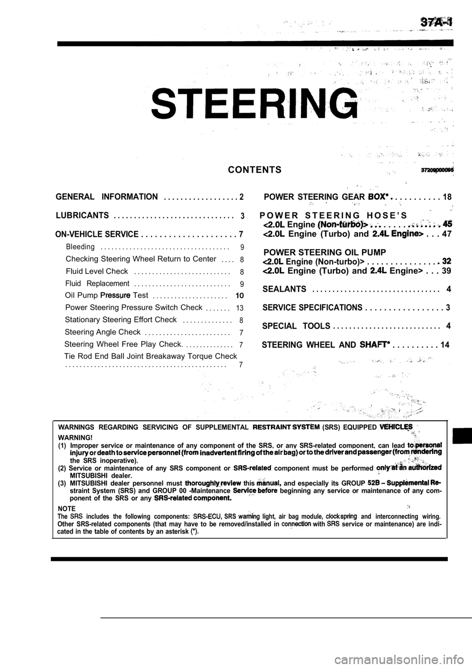
CONTENTS
GENERAL INFORMATION. . . . . . . . . . . . . . . . . . 2POWER STEERING GEAR . . . . . . . . . . 18
LUBRICANTS. . . . . . . . . . . . . . . . . . . . . . . . . . . . . .
3P O W E R S T E E R I N G H O S E ’ S
Engine . . . . .
ON-VEHICLE SERVICE . . . . . . . . . . . . . . . . . . . . . 7 Engine (Turbo) and . . . 47
Bleeding. . . . . . . . . . . . . . . . . . . . . . . . . . . . . . . . . . . .9
Checking Steering Wheel Return to Center
. . . .8
Fluid Level Check. . . . . . . . . . . . . . . . . . . . . . . . . . .8
Fluid Replacement. . . . . . . . . . . . . . . . . . . . . . . . . . .9
Oil Pump Test
. . . . . . . . . . . . . . . . . . . . .
Power Steering Pressure Switch Check
. . . . . . .13
Stationary Steering Effort Check. . . . . . . . . . . . . .8
Steering Angle Check. . . . . . . . . . . . . . . . . . . . . . . .7
Steering Wheel Free Play Check. . . . . . . . . . . . . . .7
Tie Rod End Ball Joint Breakaway Torque Check
. . . . . . . . . . . . . . . . . . . . . . . . . . . . . . . . . . . . . . . . . . . . .
7
POWER STEERING OIL PUMP
Engine (Non-turbo)> . . . . . . . . . . . . . . .
Engine (Turbo) and Engine> . . . 39
SEALANTS. . . . . . . . . . . . . . . . . . . . . . . . . . . . . . . .4
SERVICE SPECIFICATIONS . . . . . . . . . . . . . . . . . 3
SPECIAL TOOLS. . . . . . . . . . . . . . . . . . . . . . . . . . .4
STEERING WHEEL AND
. . . . . . . . . . 14
WARNINGS REGARDING SERVICING OF SUPPLEMENTAL (SRS) EQUIPPED
WARNING!(1)Improper service or maintenance of any component of the SRS, or any SRS-related component, can lead
the SRS inoperative).(2) Service or maintenance of any SRS component or component must be performed MITSUBISHI dealer.(3) MITSUBISHI dealer personnel must this and especially its GROUP straint System (SRS) and GROUP 00 -Maintenance beginning any service or maintenance of any com-
ponent of the SRS or any
NOTEThe includes the following components: SRS light, air bag module, and interconnecting wiring.Other SRS-related components (that may have to be r emoved/installed in with service or maintenance) are indi-
cated in the table of contents by an asterisk
Page 1890 of 2103
B O D Y
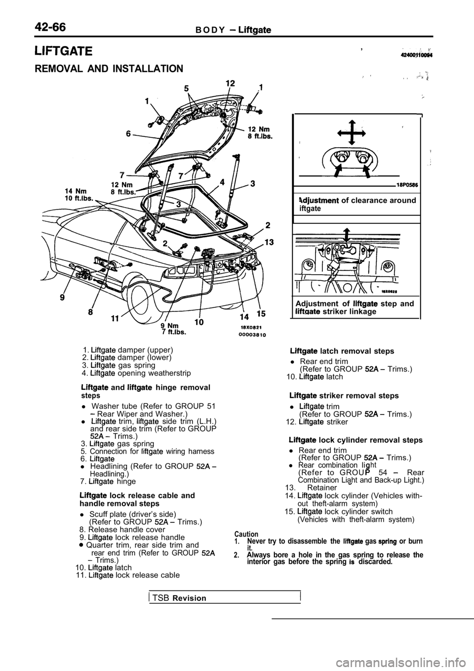
REMOVAL AND INSTALLATION
7
1. damper (upper)
2. damper (lower)
3. gas spring
4. opening weatherstrip
and hinge removal
steps
l Washer tube (Refer to GROUP 51 Rear Wiper and Washer.)
l trim, side trim (L.H.)
and rear side trim (Refer to GROUP
Trims.)
3. gas spring5. Connection for wiring harness6.l Headlining (Refer to GROUP Headlining.)7. hinge
lock release cable and
handle removal steps
l Scuff plate (driver’s side)
(Refer to GROUP
Trims.)
8. Release handle cover
9.
lock release handle Quarter trim, rear side trim andrear end trim (Refer to GROUP Trims.)10. latch
11. lock release cable ,
, ,
of clearance around
iftgate
Adjustment of step and striker linkage
latch removal steps
l Rear end trim
(Refer to GROUP
Trims.)
10. latch
striker removal steps
l
trim
(Refer to GROUP Trims.)
12. striker
lock cylinder removal steps
l Rear end trim
(Refer to GROUP
Trims.)l Rear combination Iiht( R e f e r t o G R O U54 RearCombination Liaht and Back-up Light.)13. Retainer
14. lock cylinder (Vehicles with-out theft-alarm system)
15. lock cylinder switch(Vehicles with theft-alarm system)
Caution1.Never try to disassemble the gas or burnit.2.Always bore a hole in the gas spring to release the interior gas before the spring discarded.
TSB Revision