Page 684 of 2103
FUEL SUPPLY Fuel Tank
Fuel gauge unit and
pipe assembly
Front of
Mating marks
Fuel gauge unit and
pump assembly
Mating marks
INSTALLATION SERVICE POINT
INSTALLATION ,
Use the special tool to tighten the the
so that the marks on the fuel tank the, unit
and pump assembly (or the fuel gauge and pipe assembly)
are aligned.
Caution
Make sure that the fuel gauge unit and pump assembl y
(or the fuel gauge unit and pipe assembly) does not turn
together with the cap when tightening the cap.
If the mating marks are not aligned, the position o f the
float will not be correct and the fuel gauge indicator light
and the fuel level gauge will properly.
FUEL TANK DIFFERENTIAL PRESSURE SENSOR
INSTALLATION
Caution
When removing or installing the sensor, take care n ot
to damage sealing.
TSB Revision
Page 697 of 2103

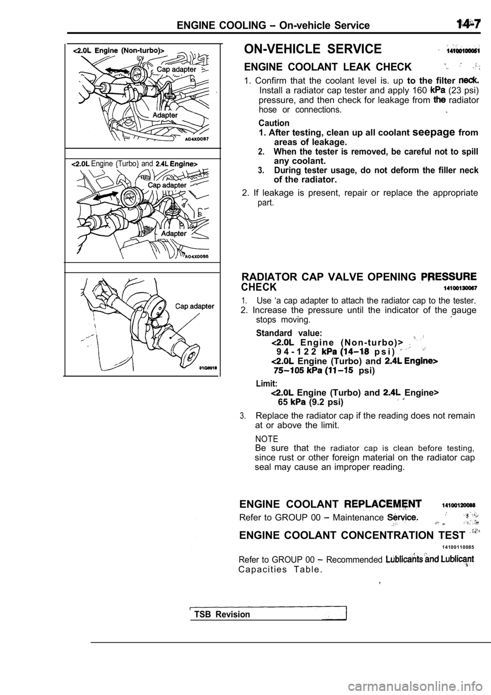
ENGINE COOLING On-vehicle Service
Engine (Turbo) and
ON-VEHICLE SERVICE
ENGINE COOLANT LEAK CHECK
1. Confirm that the coolant level is. up to the filter
Install a radiator cap tester and apply 160 (23 psi)
pressure, and then check for leakage from
radiator
hose or connections.
Caution
1. After testing, clean up all coolant seepagefrom
areas of leakage.
2.When the tester is removed, be careful not to spill
any coolant.
3.During tester usage, do not deform the filler neck
of the radiator.
2. If leakage is present, repair or replace the app ropriate
part.
RADIATOR CAP VALVE OPENING
CHECK
1.Use ‘a cap adapter to attach the radiator cap to the tester.
2. Increase the pressure until the indicator of the gauge
stops moving..
Standard value:
E n g i n e ( N o n - t u r b o ) >
9 4 - 1 2 2 p s i )
Engine (Turbo) and
psi)
Limit:
Engine (Turbo) and Engine>
65
(9.2 psi)
3.Replace the radiator cap if the reading does not re main
at or above the limit.
NOTE
Be sure that the radiator cap is clean before testing,
since rust or other foreign material on the radiato r cap
seal may cause an improper reading.
ENGINE COOLANT
Refer to GROUP 00 Maintenance
ENGINE COOLANT CONCENTRATION TEST
1 4 1 0 0 1 1 0 0 8 5
Refer to GROUP 00 Recommended
C a p a c i t i e s T a b l e . ,
TSB Revision
Page 784 of 2103
ENGINE AND EMISSION CONTROL Auto-cruise System’,
AUTO-CRUISE CONTROL INDICATOR CHECK 17200190052
(1) Remove the combination meter.(Refer to GROUP 54
Combination meter.)
(2) Check the continuity between terminals (10) and (16).
If there is no continuity, replace the auto-cruise control
indicator.
CLOCK SPRING CHECK
Refer to GROUP Air Bag Module and Clock Spring.
THROTTLE POSITION SENSOR CHECK
Engine
(Turbo) and
Engine>17200290011
Refer to GROUP On-vehicle Service.
VEHICLE SPEED SENSOR CHECK
Engine
(Non-turbo) A/T>, INPUT SPEED SENSOR OR OUTPUT
SPEED SENSOR CHECK
Engine (Non-turbo)
Refer to GROUP 54 Combination Meter.
TSB Revision
Page 1103 of 2103
AUTOMATIC TRANSAXLE
ENGINE (TURBO) AND
SELECTOR LEVER ASSEMBLY
DISASSEMBLY AND REASSEMBLY
arrow-located places)
Disassembly steps
11 Nm8.3
1. Overdrive switch position indicator12. Position indicator light assembly
light connector case
2.Cover
3. Selector knob4. Overdrive switch button5. Overdrive switch6.Pin
13.Sleeve
14.Bolt15.Lever assembly
16. Detent spring assembly17.Bushing18.Pipe19.Cotter pin20.Washer21.Lock cam22.Bracket assembly
91.5
2Nm
7. Push button8. Spring9. Indicator panel upper10. Slider11. Indicator panel lower
Terminal
Flat-tip screw driver
TSB Revision
DISASSEMBLY SERVICE POINTS
OVERDRIVE SWITCH POSITION INDICATOR
LIGHT CONNECTOR CASE REMOVAL
Use a flat-tip screwdriver or similar tool to pull out the terminal
from the overdrive switch/position indicator light connector
case.
Page 1196 of 2103

AUTOMATIC TRANSAXLE
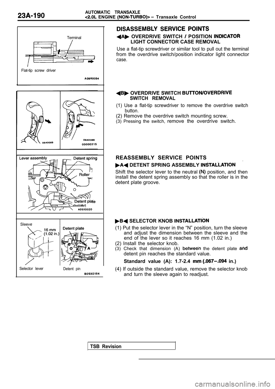
ENGINE Transaxle Control
Terminal
Flat-tip screw driver
TSB Revision
Sleeve
Selector lever
Detent pin
OVERDRIVE SWITCH POSITION
LIGHT CONNECTOR CASE REMOVAL
Use a flat-tip screwdriver or similar tool to pull out the terminal
from the overdrive switch/position indicator light connector
case.
OVERDRIVE SWITCH
SWITCH REMOVAL
(1) Use a flat-tip screwdriver to remove the overdr ive switch
button.
(2) Remove the overdrive switch mounting screw.
(3) Pressing the switch, remove the overdrive switch.
REASSEMBLY SERVICE POINTS
DETENT SPRING ASSEMBLY
Shift the selector lever to the neutral position, and then
install the detent spring assembly so that the roll er is in the
detent plate groove.
SELECTOR KNOB
(1) Put the selector lever in the “N” position, tur n the sleeve
and adjust the dimension between the sleeve and the end of the lever so it reaches 16 mm (1.02 in.)
(2) Install the selector knob.
(3) Check that dimension (A)
the detent plate
detent pin reaches the standard value.
Standard value (A): 1.7-2.4
in.)
(4) If outside the standard value, remove the selec tor knob
and turn the sleeve again to readjust.
Page 1492 of 2103

General Information/Service Specifications/
PROPELLER SHAFT Lubricants/Adhesive
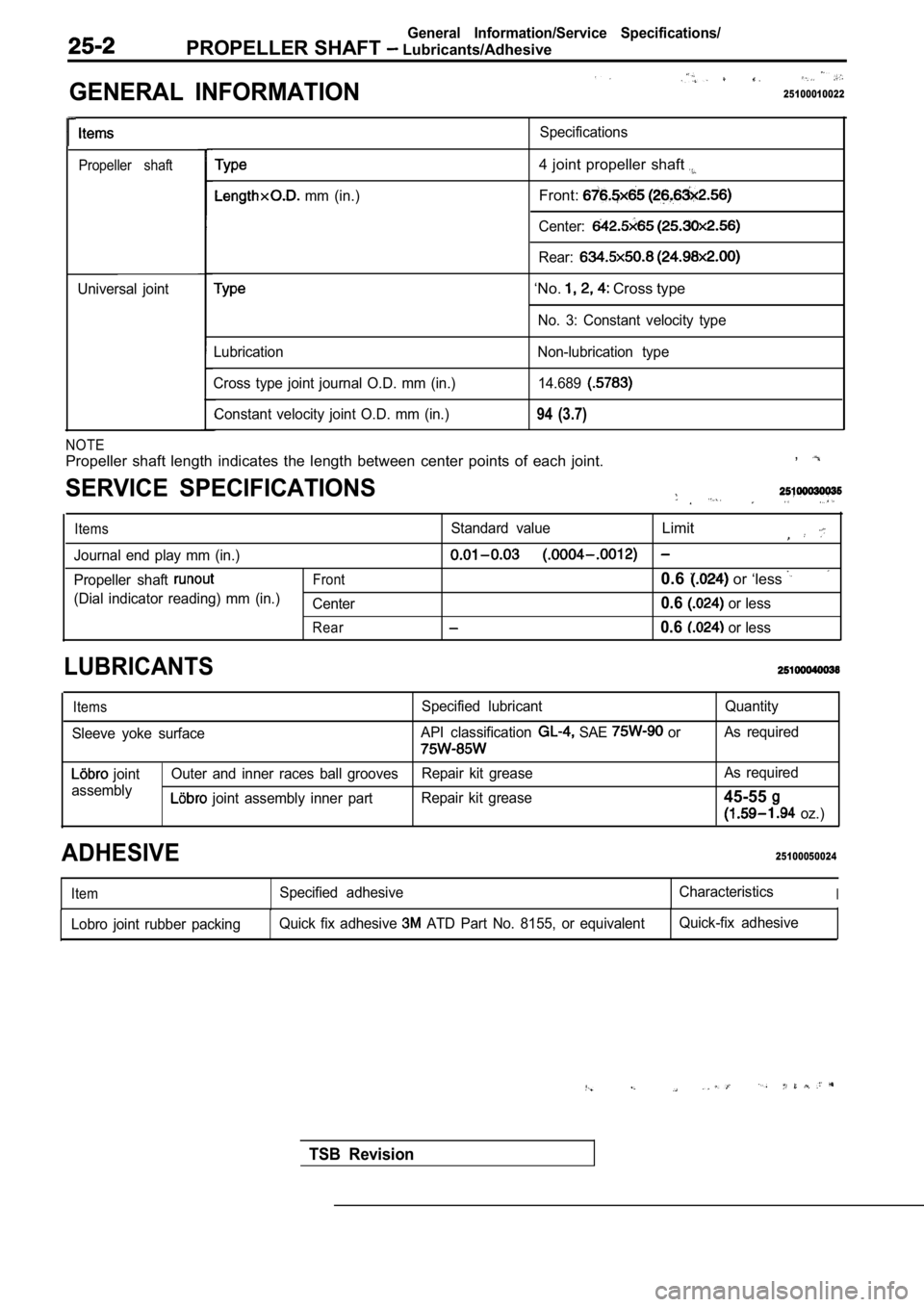
GENERAL INFORMATION
. .
25100010022
Propeller shaft
Universal jointSpecifications
mm (in.)
4 joint propeller shaft
Front:
Center:
Rear:
‘No. Cross type
No. 3: Constant velocity type
Lubrication
Cross type joint journal O.D. mm (in.) Constant velocity joint O.D. mm (in.) Non-lubrication type
14.689
94 (3.7)
NOTE
Propeller shaft length indicates the length between center points of each joint. ,
SERVICE SPECIFICATIONS
ItemsStandard valueLimit
Journal end play mm (in.)
Propeller shaft Front0.6 or ‘less
(Dial indicator reading) mm (in.)
Center0.6 or less
Rear0.6 or less
LUBRICANTS
Items
Sleeve yoke surface Specified lubricant
API classification SAE or
Quantity
As required
joint
assembly Outer and inner races ball grooves
Repair kit grease As required
joint assembly inner part
Repair kit grease45-55
oz.)
25100050024ADHESIVE
ItemSpecified adhesive CharacteristicsI
Lobro joint rubber packingQuick fix adhesive ATD Part No. 8155, or equivalent Quick-fix adhesive
TSB Revision
Page 1589 of 2103
WHEEL AND TIRE On-vehicle Service/Wheel and Tire
Wear indicator
TIRE INFLATION PRESSURE CHECK
NOTERefer to the inflation pressure label on the driver ’s side door.
TIRE WEAR CHECK
Measure the tread depth of tires.
Limit: 1.6 mm
in.)
If the remaining tread depth is less than the limit , replace
the tire.
NOTE
When the tread depth of tires is reduced to 1.6 mm
or less, wear indicators will appear.
WHEEL
CHECK
Jack up the vehicle so that the wheels are clear of the floor.
While slowly turning the wheel, measure wheel with
a dial indicator.
Limit:
Radial
Steel wheel; 1.2 mm in.) or less
Aluminum wheel; 1.0 mm
in.) or less
Lateral
Steel wheel; 1.2 mm in.) or less
Aluminum wheel; 1.0 mm
in.) or less
If wheel
exceeds the limit, replace the wheel.
INSTALLATION SERVICE POINT
Tighten the wheel nut to the specified torque.
Tightening torque:
Nm
TSB Revision
Page 1652 of 2103
4 SYSTEM Service
Pad
indicator
Brake disc
BRAKE PAD CHECK AND . .
REPLACEMENT
brake ‘pads have wear that contact
disc when ‘the brake pad 2
The wear indicators a to warn
to have the pads replaced h&e
checked.
1.Check. brake pad.
port.
Standard’ 10 mm
,
Limit: 2.0 mm in.)
Caution
When the limit is pads on
both the left and be replaced
as a set.
2. If there is, a significant in the
thicknesses of the pads on the left and right sides,
the sliding condition- of -the
pin guide pin.
2. g u i d e c a l i p e r t h e ”
assembly toward, the inside of the wheel well
from the lock Support it
Caution
Donot wipe off the special guide
pin or allow it to