1990 MITSUBISHI SPYDER wheel torque
[x] Cancel search: wheel torquePage 3 of 2103

CONTENTS
GENERAL DATA AND SPECIFICATIONS. .
HOW TO USE THIS MANUAL. . . . . . . . . . . . .3
Explanation of Manual Contents. . . . . . . . . . . . . .4
Model Indications
. . . . . . . . . . . . . . . . . . . . . . . . . . .3
Maintenance, Repair and
Servicing Explanations. . . . . . . . . . . . . . . . . . . . . . .
3
Special Tool Note. . . . . . . . . . . . . . . . . . . . . . . . . . .3
Terms Definition. . . . . . . . . . . . . . . . . . . . . . . . . . . .3
Tightening Torque Indication. . . . . . . . . . . . . . . . .3
HOW TO USE TROUBLESHOOTING/
INSPECTION SERVICE POINTS. . . . . . . . . . . .6
Connector Inspection Service Points
. . . . . . . . . .10
Connector Measurement Service Points . . . . . . . .9
How to Cope with Intermittent Malfunctions . . .11
How to Use the Inspection Procedures
. . . . . . .
8
Inspection Service Points for a Blown Fuse . . .
12
Troubleshooting Contents. . . . . . . . . . . . . . . . . . . .6
LUBRICATION AND MAINTENANCE . . . . . . .33
MAIN SEALANT AND ADHESIVE TABLE
. .
MAINTENANCE SERVICE. . . . . . . . . . . . . . . . . .38
Air Cleaner Element. . . . . . . . . . . . . . . . . . . . . . . .39
Automatic Transaxle Fluid
. . . . . . . . . . . . . . . . . . .45
Ball Joint and Steering Linkage Seals
. . . . . . . .50
Brake Hoses.... . . . . . . . . . . . . . . . . . . . . . . . . . . .50
Disc Brake Pads. . . . . . . . . . . . . . . . . . . . . . . . . . . .49
Drive Belt (For Generator, Water Pump, Power
Steering Pump). . . . . . . . . . . . . . . . . . . . . . . . . . . . .40
Drive Shaft Boots
. . . . . . . . . . . . . . . . . . . . . . . . . . .50
Engine Coolant. . . . . . . . . . . . . . . . . . . . . . . . . . . . .48
Engine Oil. . . . . . . . . . . . . . . . . . . . . . . . . . . . . . . . . .42
Engine Oil Filter. . . . . . . . . . . . . . . . . . . . . . . . . . . .43
Evaporative Emission Control System . . . . . . . . .
Exhaust System. . . . . . . . . . . . . . . . . . . . . . . . . . . . .54
Fuel Hoses. . . . . . . . . . . . . . . . . . . . . . . . . . . . . . . . .38
Fuel System. . . . . . . . . . . . . . . . . . . . . . . . . . . . . . . .38
Ignition Cables. . . . . . . . . . . . . . . . . . . . . . . . . . . . . .
40
Manual Transaxle Oil . . . . . . . . . . . . . . . . . . . . . . . .
Rear Axle Oil. . . . . . . . . . . . . . . . . . . . . . . . . . . .
50
Rear Drum Brake Linings and
Rear Wheel Cylinders . . . . . . . . . . . . . . . . . . . . . . .
Spark Plugs. . . . . . . . . . . . . . . . . . . . . . . . . . . . . . . .40
SRS System . . . . . . . . . . . . . . . . . . . . . . . . . . . . . . .51
Timing Belt. . . . . . . . . . . . . . . . . . . . . . . . . . . . . . . . .40
Transfer Oil. . . . . . . . . . . . . . . . . . . . . . . . . . . . . . . .48
PRECAUTIONS BEFORE SERVICE. . . . . . . .20
RECOMMENDED LUBRICANTS
LUBRICANT CAPACITIES TABLE. . . . . . . . . .34
SCHEDULED MAINTENANCE TABLE. . . . .
SPECIAL HANDLING INSTRUCTIONS FOR
AWD MODELS . . . . . . . . . . . . . . . . . . . . . . . . . . . .
26
TIGHTENING TORQUE. . . . . . . . . . . . . . . . . . . .32
TOWING AND HOISTING . . . . . . . . . . . . . . . . . .22
VEHICLE IDENTIFICATION. . . . . . . . . . . . . . . . .13
Engine Model Stamping. . . . . . . . . . . . . . . . . . . . .15
Theft Protection. . . . . . . . . . . . . . . . . . . . . . . . . . . . .18
Vehicle Identification Code Chart Plate
. . . . . . .13
Vehicle Identification Number List. . . . . . . . . . . .14
Vehicle Identification Number Location. . . . . . . .13
Vehicle Information Code Plate.. . . . . . . . . . . . . .15
Vehicle Safety Certification Label
. . . . . . . . . . . . .15
Page 5 of 2103
GENERAL How to Use This
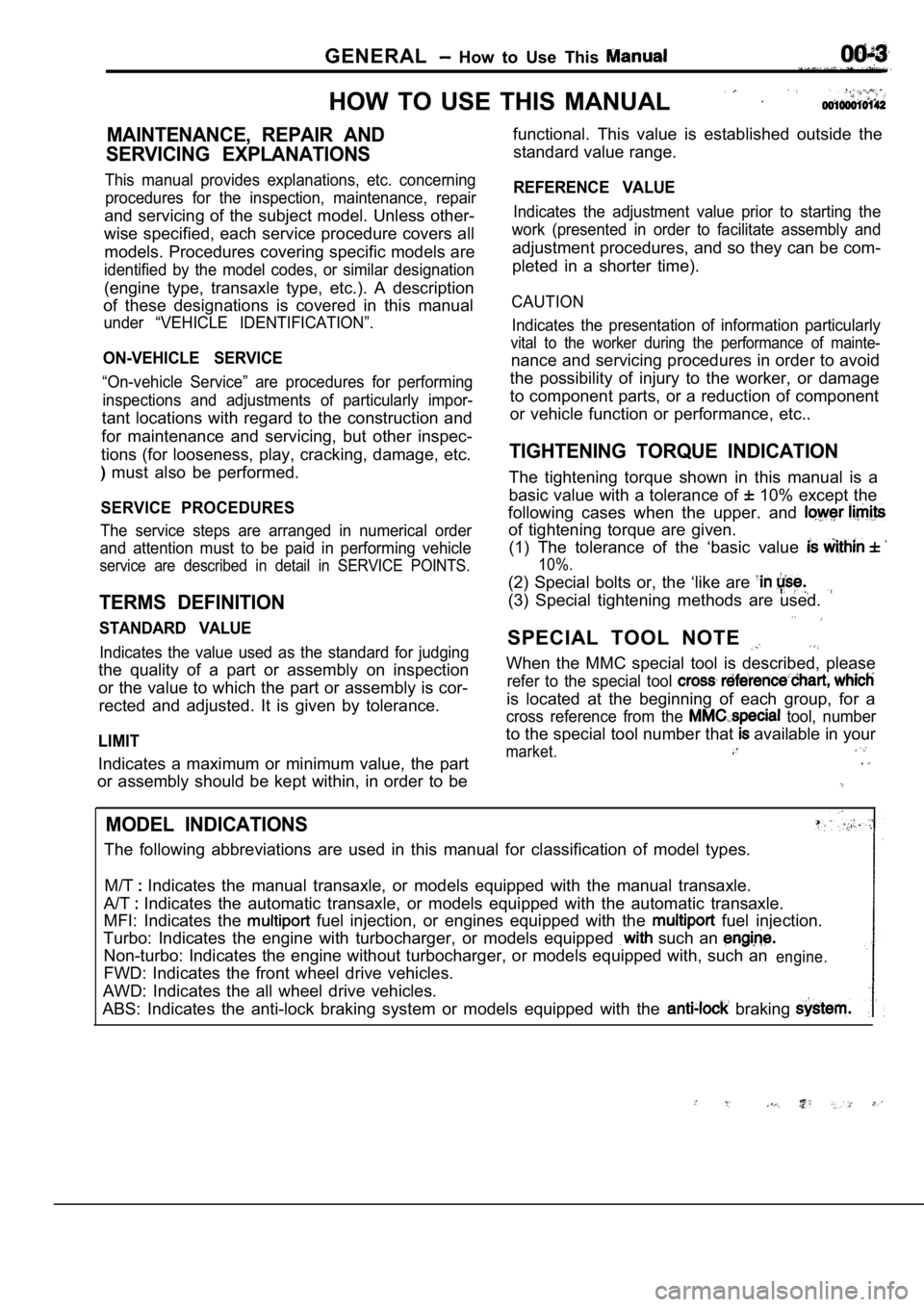
HOW TO USE THIS MANUAL
MAINTENANCE, REPAIR AND
SERVICING EXPLANATIONS
This manual provides explanations, etc. concerning procedures for the inspection, maintenance, repair
and servicing of the subject model. Unless other-
wise specified, each service procedure covers all
models. Procedures covering specific models are
identified by the model codes, or similar designati on
(engine type, transaxle type, etc.). A description
of these designations is covered in this manual
under “VEHICLE IDENTIFICATION”.
ON-VEHICLE SERVICE
“On-vehicle Service” are procedures for performing
inspections and adjustments of particularly impor-
tant locations with regard to the construction and
for maintenance and servicing, but other inspec-
tions (for looseness, play, cracking, damage, etc.
must also be performed.
SERVICE PROCEDURES
The service steps are arranged in numerical order
and attention must to be paid in performing vehicle
service are described in detail in SERVICE POINTS.
TERMS DEFINITION
STANDARD VALUE
Indicates the value used as the standard for judgin g
the quality of a part or assembly on inspection
or the value to which the part or assembly is cor-
rected and adjusted. It is given by tolerance.
LIMIT
Indicates a maximum or minimum value, the part
or assembly should be kept within, in order to be functional. This value is established outside the
standard value range.
REFERENCE VALUE
Indicates the adjustment value prior to starting th e
work (presented in order to facilitate assembly and
adjustment procedures, and so they can be com-
pleted in a shorter time).
CAUTION
Indicates the presentation of information particula rly
vital to the worker during the performance of maint e-
nance and servicing procedures in order to avoid
the possibility of injury to the worker, or damage
to component parts, or a reduction of component
or vehicle function or performance, etc..
TIGHTENING TORQUE INDICATION
The tightening torque shown in this manual is a
basic value with a tolerance of
10% except the
following cases when the upper. and
of tightening torque are given. (1) The tolerance of the ‘basic value
10%.
(2) Special bolts or, the ‘like are
(3) Special tightening methods are used.
SPECIAL TOOL NOTE
When the MMC special tool is described, please
refer to the special tool
is located at the beginning of each group, for a
cross reference from the tool, number
to the special tool number that available in your
market..
MODEL INDICATIONS
The following abbreviations are used in this manual for classification of model types.
M/T
Indicates the manual transaxle, or models equipped with the manual transaxle.
A/T
Indicates the automatic transaxle, or models equip ped with the automatic transaxle.
MFI: Indicates the
fuel injection, or engines equipped with the fuel injection.
Turbo: Indicates the engine with turbocharger, or m odels equipped
such an
Non-turbo: Indicates the engine without turbocharger, or models equipped with, such anengine.
FWD: Indicates the front wheel drive vehicles.
AWD: Indicates the all wheel drive vehicles.
ABS: Indicates the anti-lock braking system or mode ls equipped with the
braking
Page 90 of 2103
11ENGINE Crankshaft pear Oil
,
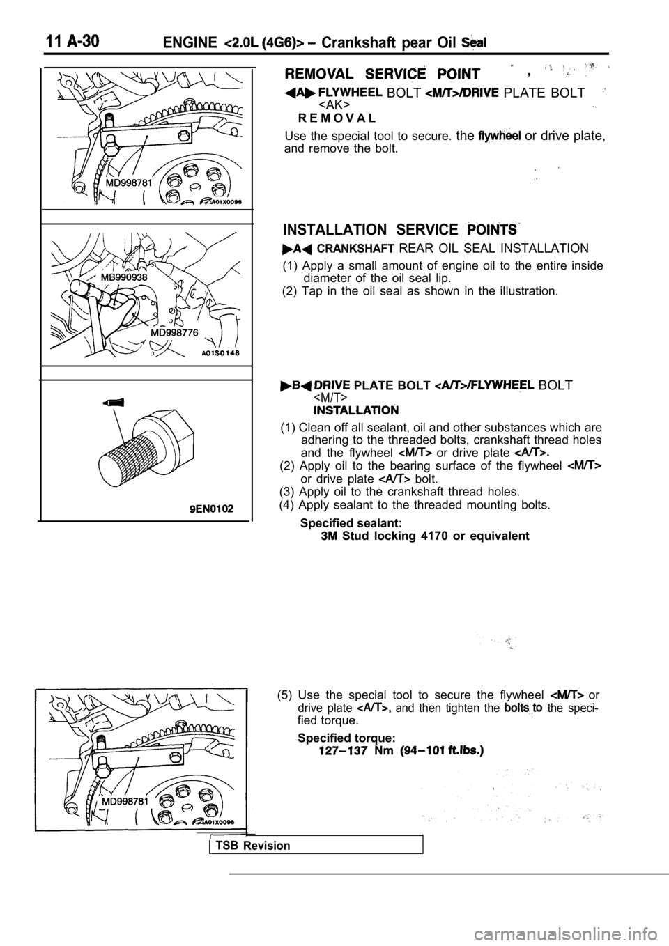
BOLT PLATE BOLT
R E M O V A L
Use the special tool to secure. the
or drive plate,
and remove the bolt.
INSTALLATION SERVICE
CRANKSHAFT REAR OIL SEAL INSTALLATION
(1) Apply a small amount of engine oil to the entir e inside
diameter of the oil seal lip.
(2) Tap in the oil seal as shown in the illustratio n.
PLATE BOLT BOLT
(1) Clean off all sealant, oil and other substances which are
adhering to the threaded bolts, crankshaft thread h oles
and the flywheel
or drive plate
(2) Apply oil to the bearing surface of the flywhee l
or drive plate bolt.
(3) Apply oil to the crankshaft thread holes.
(4) Apply sealant to the threaded mounting bolts.
Specified sealant:
Stud locking 4170 or equivalent
TSB Revision
(5) Use the special tool to secure the flywheel or
drive plate and then tighten the the speci-
fied torque.
Specified torque:
Nm
Page 105 of 2103
CONTENTS
BRACKET65
CRANKSHAFT, FLYWHEEL ANDDRIVE PLATE
. . . . . . . . . . . . . . . . . . . . . . . . . . . . .59
CYLINDER HEAD AND VALVES . . . . . . . . . . . 36
EXHAUST MANIFOLD AND
WATER PUMP. . . . . . . * . . . . . . . . . . . . . . . . . . . .29
FRONT CASE, COUNTERBALANCE
SHAFT AND OIL PAN . . . . . . . . . . . . . . . . . . . . . 42
FUEL AND EMISSION CONTROL
PARTS. . . . . . . . . . . . . . . . . . . . . . . . . . . . . . . . . . .25
GENERAL INFORMATION. . . . . . . . . . . . . . . . . .2
General Specifications . . . . . . . . . . . . . . . . . . , . . . . .2
GENERATOR IGNITION SYSTEM. . . . .11
INTAKE MANIFOLD. . . . . . . . . . . . . . . . . . . . . .
PISTON AND CONNECTING ROD..
. . . . . . . .51
ROCKER ARMS AND CAMSHAFT. . . . . . . .
SPECIAL TOOLS
. . . . . . . . . . . . . . . . . . . . . . . . . . .8
SPECIFICATIONS. . . . . . . . . . . . . . . . . . . . . . . . . .3
Rework Dimensions. . . . . . . . . . . . . . . . . . . . . . . . . .4
Sealant. . . . . . . . . . . . . . . . . . . . . . . . . . . . . . . . . .. . ..
Service Specifications. . . . . . . . . . . . . . . . . . . ....3
Torque Specifications. . . . . . . . . . . . . . . . . . . . . . . . . . . .5
TIMING BELT
. . . . . . . . . . . . . . . . . .. . . . . . . . .
,
Page 247 of 2103
E N G I N E O V E R H A U L Oil ‘Pan and Oil Pump
Locating
I
adapter
Locate wrench
at base of filter
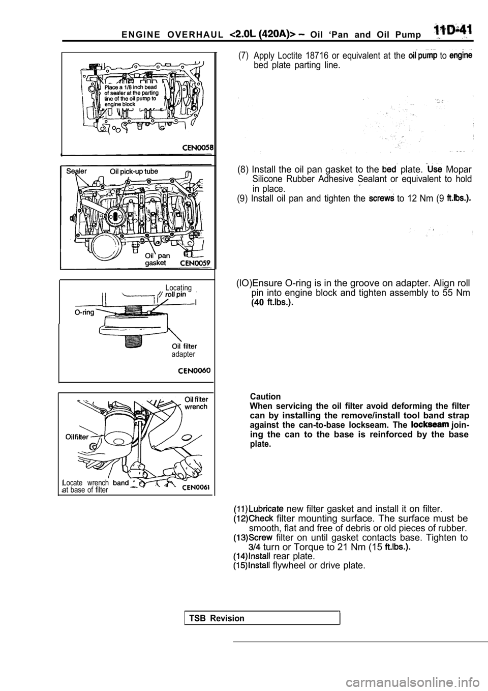
(7)Apply Loctite 18716 or equivalent at the to
bed plate parting line.
(8) Install the oil pan gasket to the plate. Mopar
Silicone Rubber Adhesive Sealant or equivalent to h old
in place.
(9) Install oil pan and tighten the to 12 Nm (9
(lO)Ensure O-ring is in the groove on adapter. Alig n roll
pin into engine block and tighten assembly to 55 Nm
(40
Caution
When servicing the oil filter avoid deforming the f ilter
can by installing the remove/install tool band strap
against the can-to-base lockseam. The join-
ing the can to the base is reinforced by the base
plate.
new filter gasket and install it on filter.
filter mounting surface. The surface must be
smooth, flat and free of debris or old pieces of rubber.
filter on until gasket contacts base. Tighten to
turn or Torque to 21 Nm (15
rear plate.
flywheel or drive plate.
TSB Revision
Page 271 of 2103
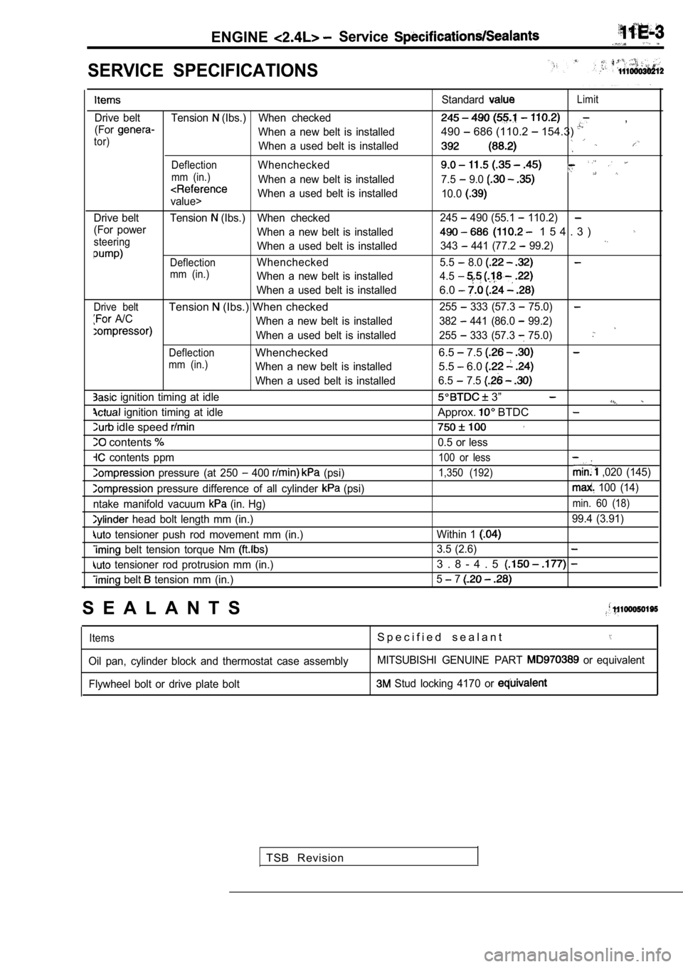
ENGINEService
SERVICE SPECIFICATIONS
Drive belt Tension (Ibs.) When checked
(For
When a new belt is installedtor)When a used belt is installed
DeflectionWhenchecked
mm (in.)When a new belt is installed
value> When a used belt is installed
Drive belt Tension
(Ibs.) When checked
(For power When a new belt is installed
steeringWhen a used belt is installed
DeflectionWhenchecked
mm (in.)When a new belt is installed
When a used belt is installed
Drive beltTension (Ibs.) When checked
A/C When a new belt is installed
When a used belt is installed
DeflectionWhenchecked
mm (in.)When a new belt is installed
When a used belt is installed
ignition timing at idle
ignition timing at idle
idle speed
contents
contents ppm
pressure (at 250 400 (psi)
pressure difference of all cylinder (psi)
ntake manifold vacuum
(in. Hg)
head bolt length mm (in.)
tensioner push rod movement mm (in.)
belt tension torque Nm
tensioner rod protrusion mm (in.)
belt tension mm (in.) Standard
Limit
,
490
686 (110.2 154.3)
7.5 9.0
10.0
245 490 (55.1 110.2)
1 5 4 . 3 )
343 441 (77.2 99.2)
5.5 8.0
4.5
6.0
255 333 (57.3 75.0)
382 441 (86.0 99.2)
255
333 (57.3 75.0)
6.5 7.5
5.5 6.0
6.5 7.5
3”
Approx. BTDC
0.5 or less
100 or less
1,350 (192) ,020 (145)
100 (14)
min. 60 (18)
99.4 (3.91)
Within 1
3.5 (2.6)
3 . 8 - 4 . 5
5 7
S E A L A N T S
ItemsS p e c i f i e d s e a l a n t
Oil pan, cylinder block and thermostat case assembl yMITSUBISHI GENUINE PART or equivalent
Flywheel bolt or drive plate bolt
Stud locking 4170 or
TSB Revision
Page 296 of 2103
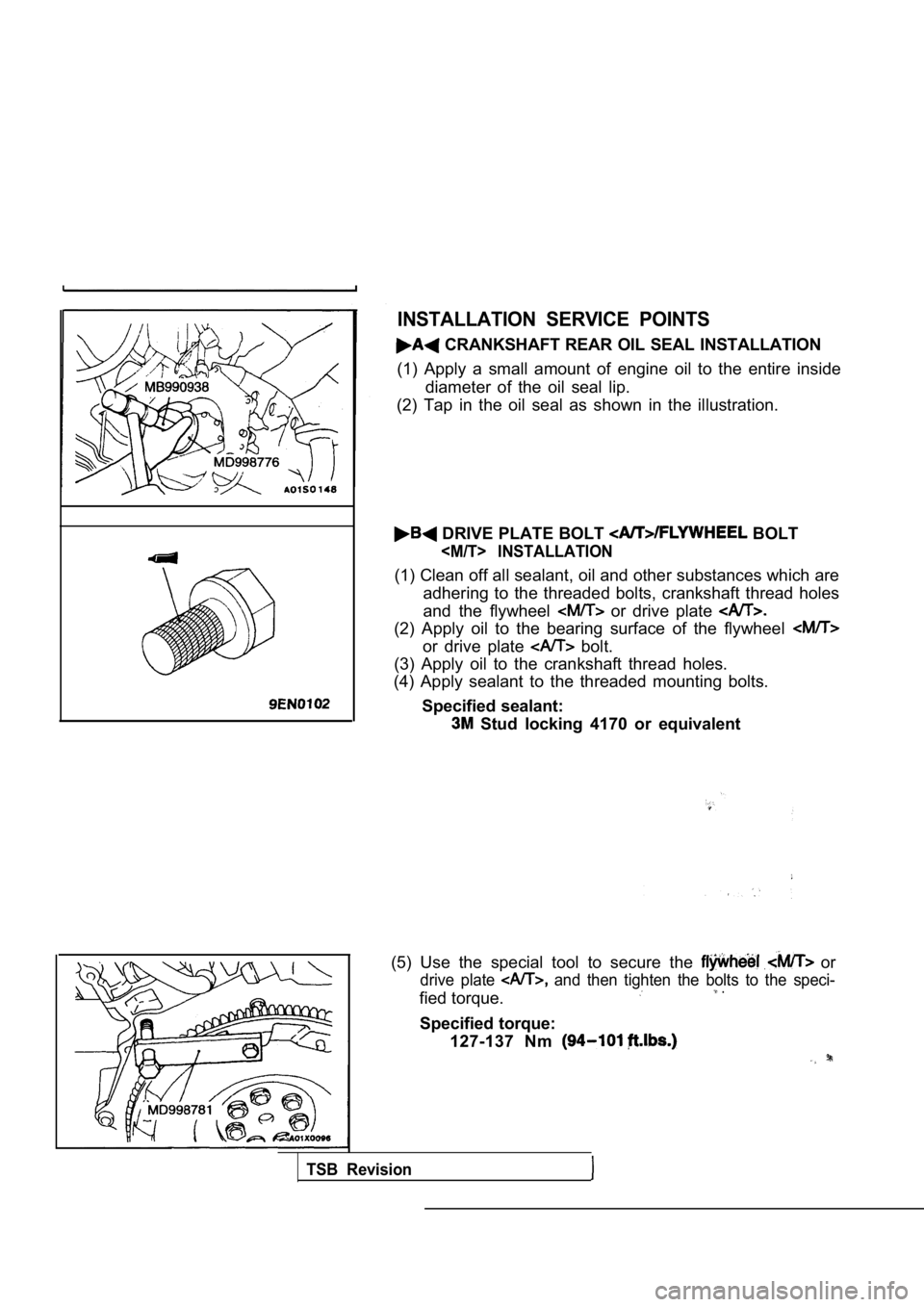
INSTALLATION SERVICE POINTS
CRANKSHAFT REAR OIL SEAL INSTALLATION
(1) Apply a small amount of engine oil to the entir e inside
diameter of the oil seal lip.
(2) Tap in the oil seal as shown in the illustratio n.
DRIVE PLATE BOLT BOLT
(1) Clean off all sealant, oil and other substances which are
adhering to the threaded bolts, crankshaft thread h oles
and the flywheel
or drive plate
(2) Apply oil to the bearing surface of the flywhee l
or drive plate bolt.
(3) Apply oil to the crankshaft thread holes.
(4) Apply sealant to the threaded mounting bolts.
Specified sealant:
Stud locking 4170 or equivalent
(5) Use the special tool to secure the
or
drive plate and then tighten the bolts to the speci-
fied torque. .
Specified torque: 127-137 Nm
TSB Revision
Page 314 of 2103
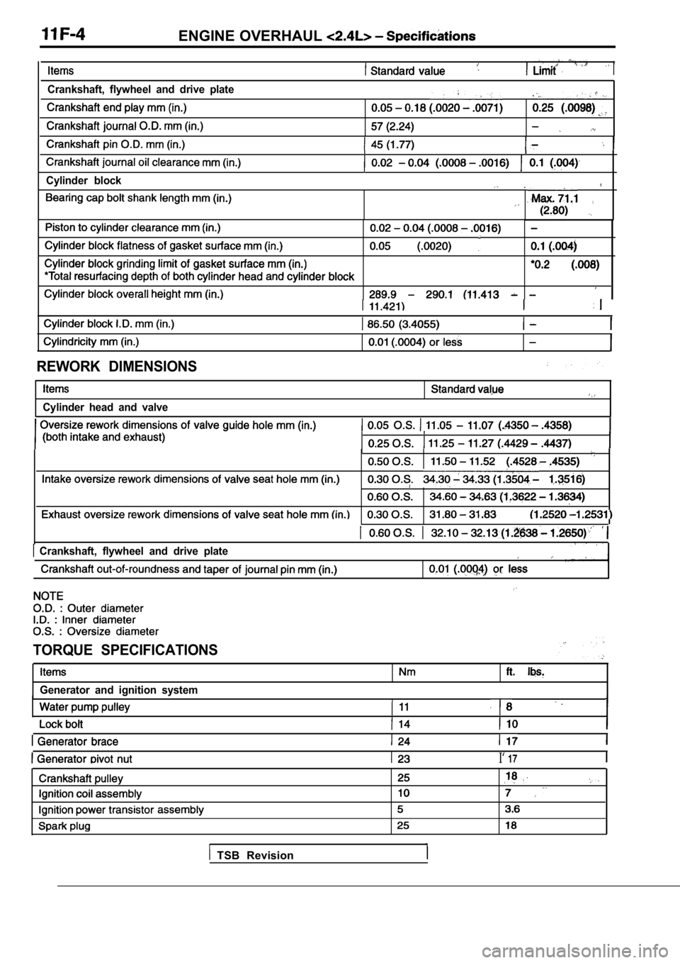
ENGINE OVERHAUL
Crankshaft, flywheel and drive plate,
Cylinder block
REWORK DIMENSIONS
Cylinder head and valve
Crankshaft, flywheel and drive plate
TORQUE SPECIFICATIONS
Generator and ignition system
I‘
TSB Revision