1990 MITSUBISHI SPYDER seats
[x] Cancel search: seatsPage 145 of 2103
ENGINE OVERHAUL Cylinder Head and Valves,
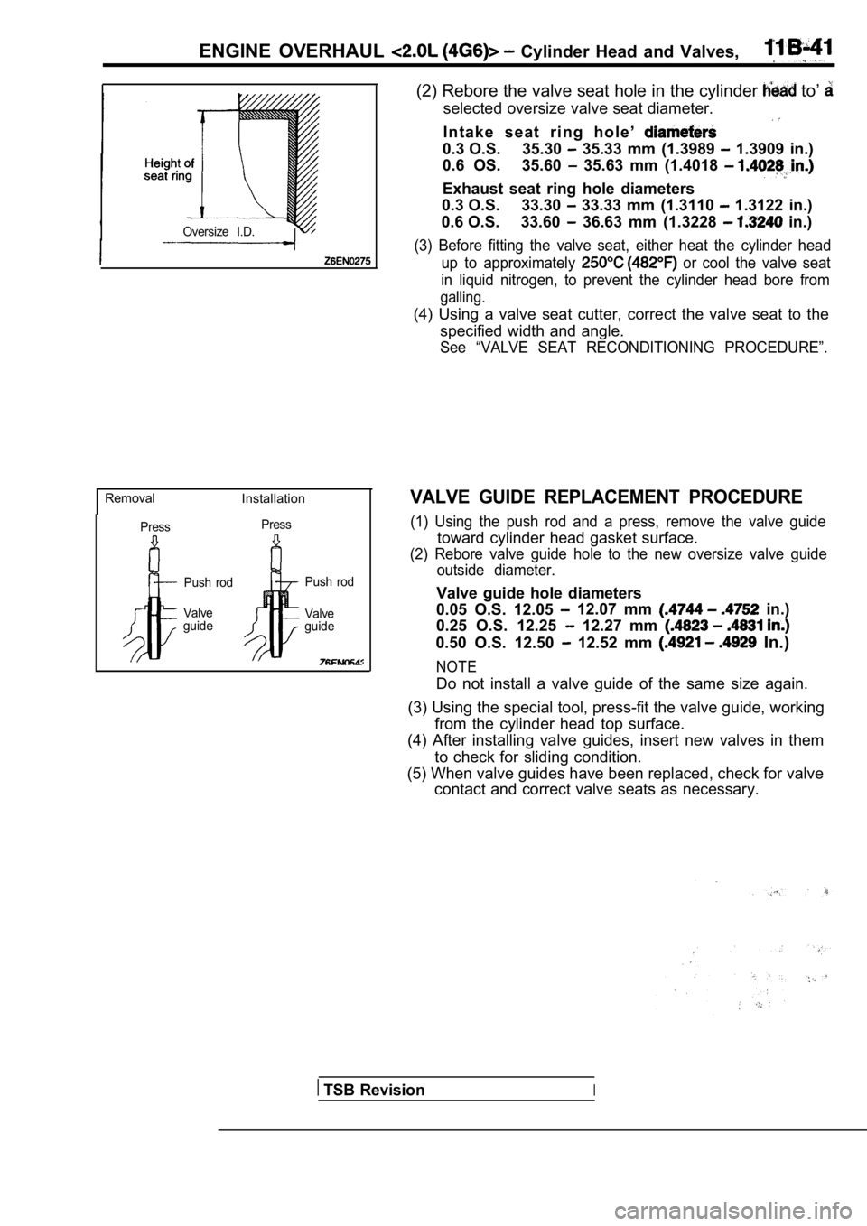
Oversize I.D.
RemovalInstallation
PressPress
Push rod
Valve
guide Push rod
Valve
guide
(2) Rebore the valve seat hole in the cylinder to’
selected oversize valve seat diameter.
I n t a k e s e a t r i n g h o l e ’
0.3 O.S. 35.30 35.33 mm (1.3989 1.3909 in.)
0.6 OS. 35.60
35.63 mm (1.4018
Exhaust seat ring hole diameters
0.3 O.S. 33.30
33.33 mm (1.3110 1.3122 in.)
0.6 O.S. 33.60
36.63 mm (1.3228 in.)
(3) Before fitting the valve seat, either heat the cylinder head
up to approximately
or cool the valve seat
in liquid nitrogen, to prevent the cylinder head bo re from
galling.
(4) Using a valve seat cutter, correct the valve seat to the
specified width and angle.
See “VALVE SEAT RECONDITIONING PROCEDURE”.
VALVE GUIDE REPLACEMENT PROCEDURE
(1) Using the push rod and a press, remove the valv e guide
toward cylinder head gasket surface.
(2) Rebore valve guide hole to the new oversize valve guide
outside diameter.
Valve guide hole diameters
0.05 O.S. 12.05
12.07 mm in.)
0.25 O.S. 12.25
12.27 mm
0.50 O.S. 12.50 12.52 mm In.)
NOTE
Do not install a valve guide of the same size again .
(3) Using the special tool, press-fit the valve gui de, working
from the cylinder head top surface.
(4) After installing valve guides, insert new valve s in them
to check for sliding condition.
(5) When valve guides have been replaced, check for valve
contact and correct valve seats as necessary.
TSB RevisionI
Page 239 of 2103
ENGINE OVERHAUL Cylinder and Valve
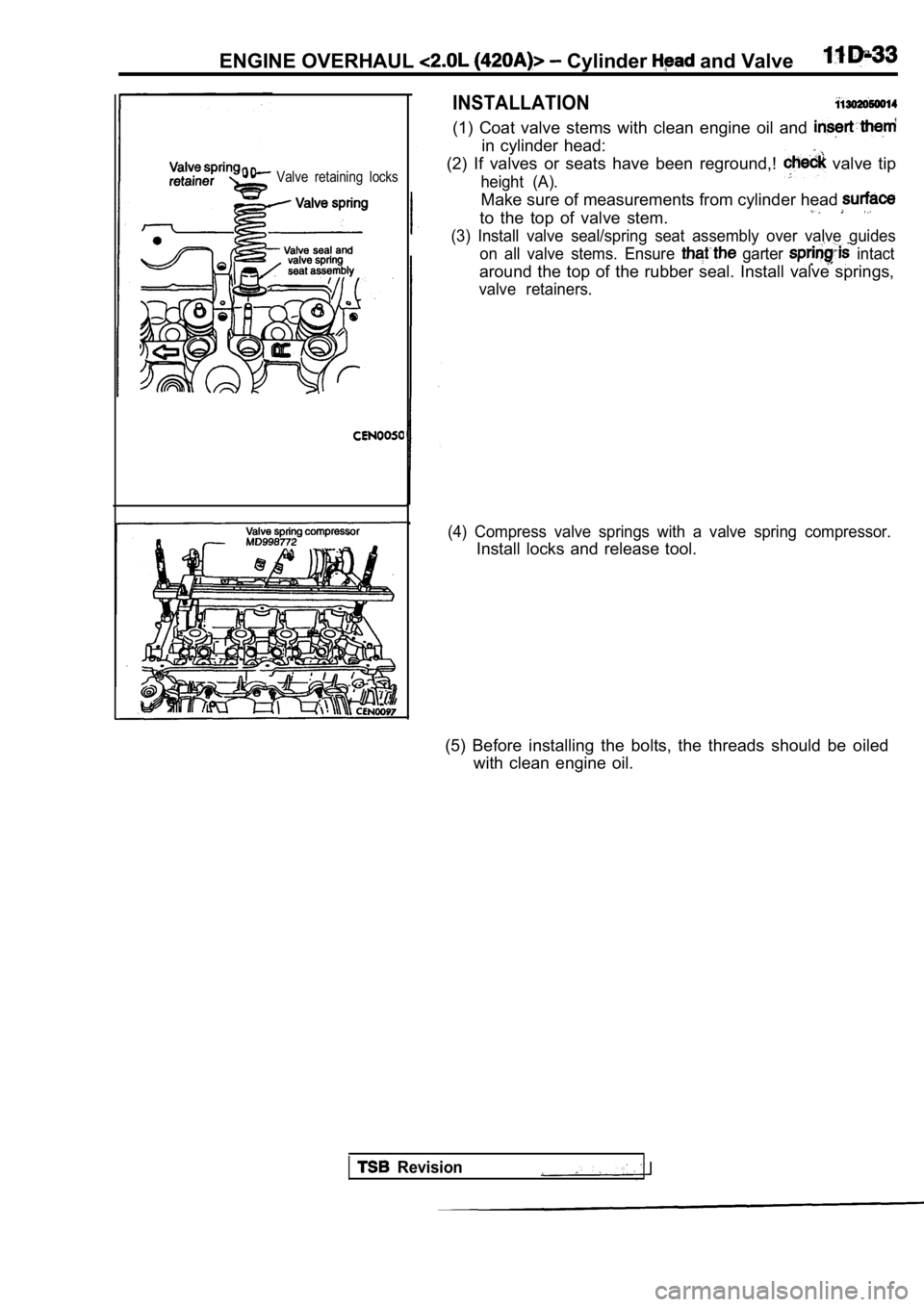
Valve retaining locks
INSTALLATION
(1) Coat valve stems with clean engine oil and
in cylinder head:
(2) If valves or seats have been reground,!
valve tip
height (A).
Make sure of measurements from cylinder head
(3) Install valve seal/spring seat assembly over va lve guides
to the top of valve stem.
on all valve stems. Ensure garter intact
around the top of the rubber seal. Install valve springs,
valve retainers.
(4) Compress valve springs with a valve spring comp ressor.
Install locks and release tool.
(5) Before installing the bolts, the threads should be oiled
with clean engine oil.
Revision
Page 242 of 2103
1 1 E N G I N E O V E R H A U L Head and
wrench at this instant. Multiply this reading by This
will give the spring load at test length. Fractional measure-
ments are indicated on the table for finer adjustme nts.
Refer to specifications to obtain specified and allow-
able tensions.
Discard the springs that
cations.
Standard value: Free length 46 mm
in.)
Spring tensionV a l v e
m i n
i n . )
Valve open 459-611
mm
(123-137
in.)
(2) inspect each valve spring for squareness with a steel
square and surface plate, test springs from both en ds.
If the spring is more than 1.5 mm in.) out of square,
install a new spring.
REFACING VALVES AND VALVE SEATS
(1) The intake and exhaust valve seats and valve fa ce have
a 45 degree angle.
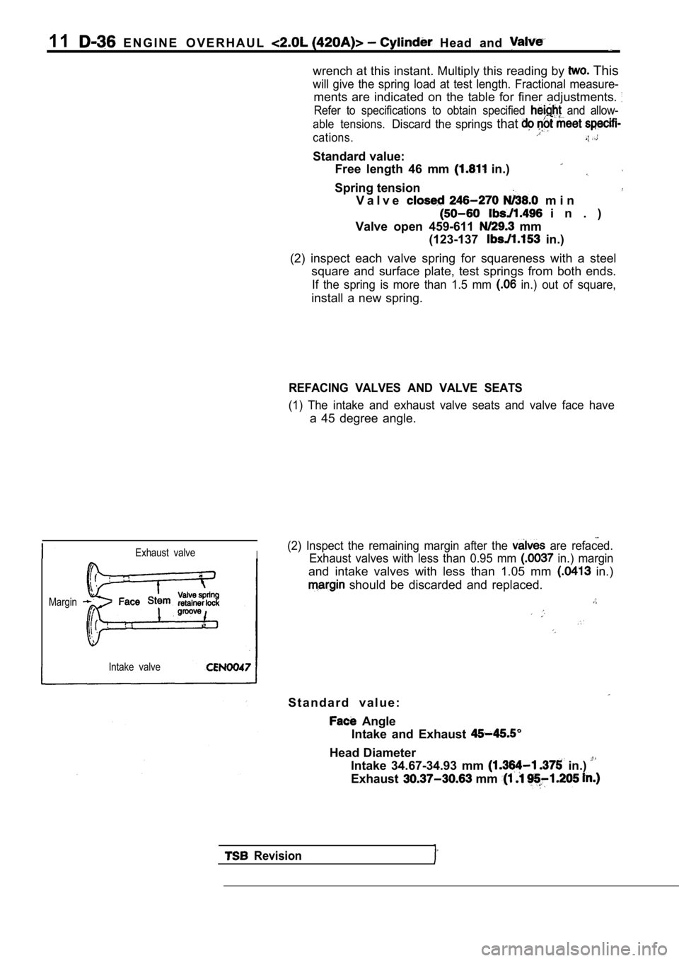
Exhaust valveI
Margin
Intake valve
(2) Inspect the remaining margin after the are refaced.
Exhaust valves with less than 0.95 mm
in.) margin
and intake valves with less than 1.05 mm in.)
should be discarded and replaced.
S t a n d a r d v a l u e :
Angle
Intake and Exhaust
Head Diameter Intake 34.67-34.93 mm
in.)
Exhaust mm
Revision
Page 243 of 2103
(Overall)
Intake 111.49-111.99 mm (4.389-4.499 in.) Exhaust
mm in.)
Stem Diameter
Intake 5.934-5.952 mm in.)
Exhaust
mm in.)
Valve Margin
Intake 1.285-1.615 mm in.)
Exhaust
mm in.)
(3) When refacing valve seats, it is important that the correct
size valve guide pilot be used for reseating A
true and complete surface must
Measure the concentricity of valve seat using a va lve
seat dial indicator. Circular
should not exceed.
Limit:
0.05 mm in.) Indicator reading.
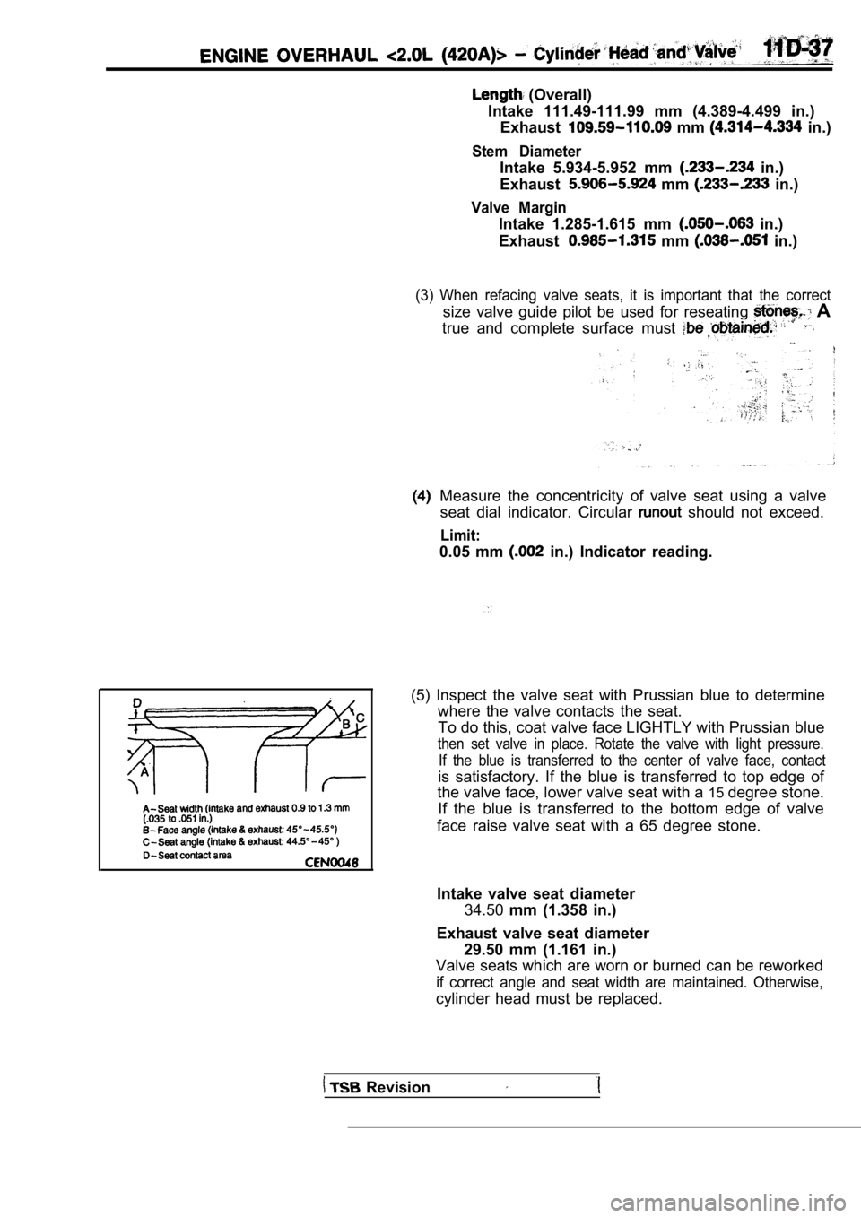
(5) Inspect the valve seat with Prussian blue to de termine
where the valve contacts the seat.
To do this, coat valve face LIGHTLY with Prussian b lue
then set valve in place. Rotate the valve with light pressure.
If the blue is transferred to the center of valve f ace, contact
is satisfactory. If the blue is transferred to top edge of
the valve face, lower valve seat with a 15degree stone.
If the blue is transferred to the bottom edge of va lve
face raise valve seat with a 65 degree stone.
Intake valve seat diameter 34.50 mm (1.358 in.)
Exhaust valve seat diameter 29.50 mm (1.161 in.)
Valve seats which are worn or burned can be reworke d
if correct angle and seat width are maintained. Otherwise,
cylinder head must be replaced.
Revision
Page 244 of 2103
11ENGINE OVERHAUL Cylinder Head
(6) seat is properly positioned, the width of intake
and exhaust seats should be 0.9 to 1.3 mm
to
in.).
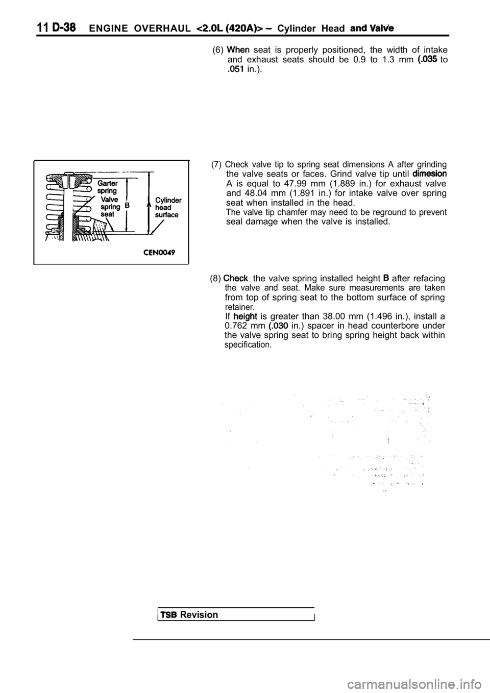
(7) Check valve tip to spring seat dimensions A aft er grinding
the valve seats or faces. Grind valve tip until
A is equal to 47.99 mm (1.889 in.) for exhaust valv e
and 48.04 mm (1.891 in.) for intake valve over spri ng
seat when installed in the head.
The valve tip chamfer may need to be reground to pr event
seal damage when the valve is installed.
(8)
the valve spring installed height after refacing
the valve and seat. Make sure measurements are take n
from top of spring seat to the bottom surface of spring
retainer.
If is greater than 38.00 mm (1.496 in.), install a
0.762 mm
in.) spacer in head counterbore under
the valve spring seat to bring spring height back w ithin
specification.
RevisionI
Page 349 of 2103
ENGINE OVERHAUL Cylinder Head and Valves
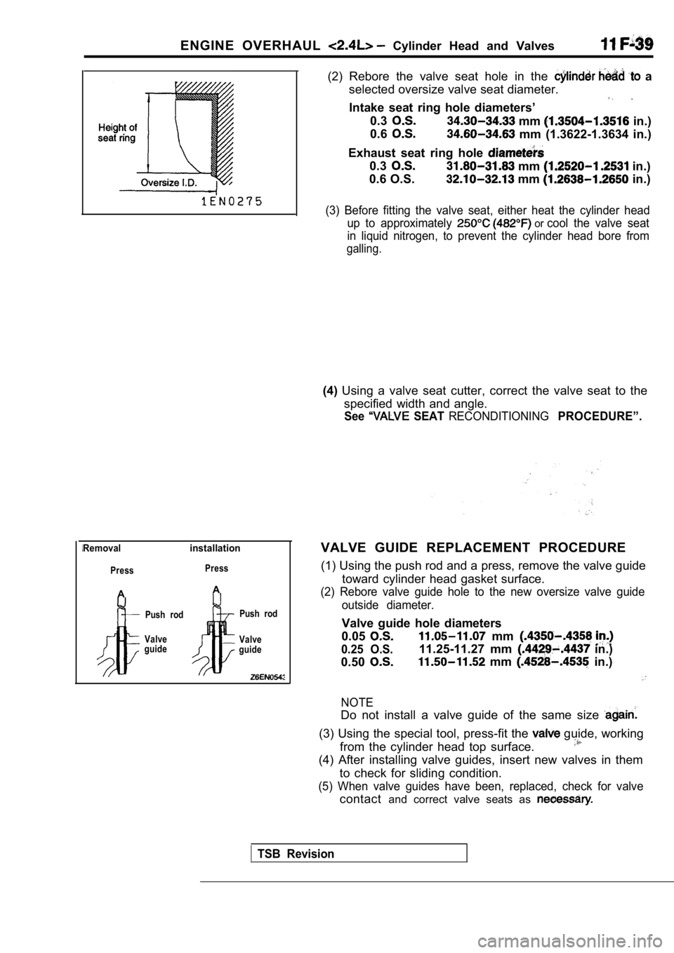
Removalinstallation
Press
A
Press
A
Push rod
Valve
guide Push rod
Valve
guide
(2) Rebore the valve seat hole in the a
selected oversize valve seat diameter.
Intake seat ring hole diameters’
0.3 mm in.)
0.6
mm (1.3622-1.3634 in.)
Exhaust seat ring hole
0.3 mm in.)
0.6 O.S.
mm in.)
(3) Before fitting the valve seat, either heat the cylinder head
up to approximately
or cool the valve seat
in liquid nitrogen, to prevent the cylinder head bo re from
galling.
(4)Using a valve seat cutter, correct the valve seat t o the
specified width and angle.
See SEAT RECONDITIONINGPROCEDURE”.
VALVE GUIDE REPLACEMENT PROCEDURE
(1) Using the push rod and a press, remove the valv e guide
toward cylinder head gasket surface.
(2) Rebore valve guide hole to the new oversize val ve guide
outside diameter.
Valve guide hole diameters
0.05
0.25 O.S.
mm
0.50
11.25-11.27 mm in.)
mm in.)
NOTE
Do not install a valve guide of the same size
(3) Using the special tool, press-fit the guide, working
from the cylinder head top surface.
(4) After installing valve guides, insert new valve s in them
to check for sliding condition.
(5) When valve guides have been, replaced, check fo r valve
contactand correct valve seats as
TSB Revision
Page 678 of 2103
FUEL SUPPLY Fuel Tank
13500010032
(1) The fuel tank is located under the floor of the The fuel tank AWD from a high
rear seats to provide increased safety. density: pol yethylene
material and
(2)A fuel cut-off valve has been’adopted to preventblow-formed an ‘tank.
fuel from leaking out in the event of a collision.
Specifications
Fuel tank capacity (gals.)
Fuel pump type64 (16.9)
Electrical, in-tank type
ItemsStandard value.
Fuel tank differential pressure sensor output volta ge 2.0 3.0 ,
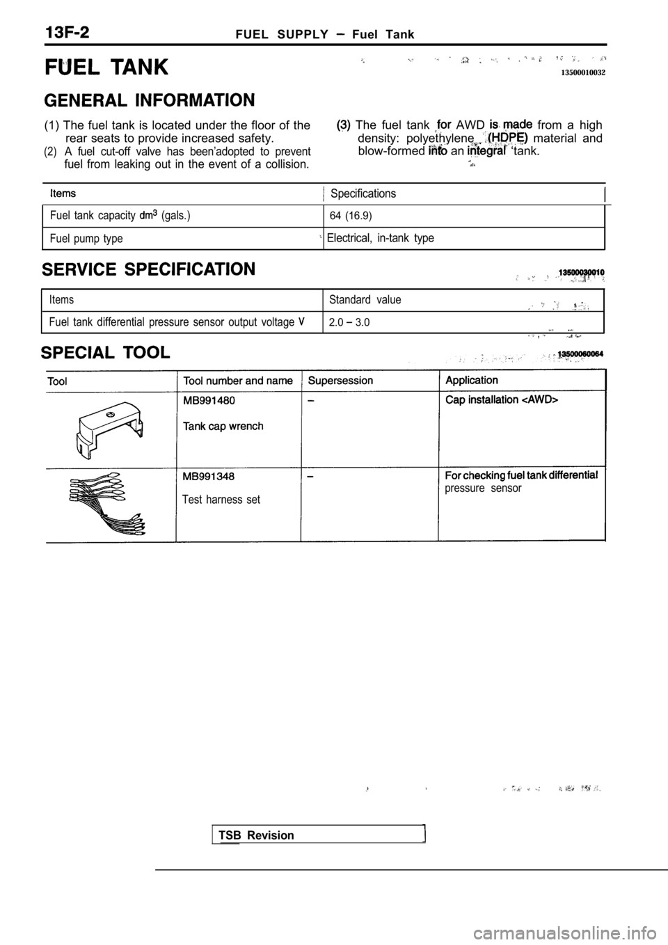
Test harness set pressure sensor
TSB Revision
Page 2001 of 2103
SRS General- Jnformation
Label
A WARNING TO AVOID SERIOUS INJURY:DANGER POISON
For maximum safety protection in all types ofKeep out of the reach of children. Contains sodium
crashes, you must always wear your safety belt. azide and potassium nitrate contents are poisonous
Do not install rearward-facing child seats in any f
rontand extremely flammable. Contact with acid, water,
passenger seat position. or heavy metals may produce harmful and irritating
Do not sit or lean unnecessarily
close to the air bag. gasesor explosive compounds. Do not dismantle,
Do not place any objects over the air bag or betwee
nincinerate, bring into contact with electricity or store
the air bag and yourself. at temperatures exceeding
See the owner’s manual for further information andFIRST AID: If contents are swallowed induce
explanations.vomiting. For eye contact flush eye for 5
minutes. If gases from acid
inhaled, seek fresh air. In every case, get prompt
medical attention.
For additional information, see material safety dat a
sheet (MSDS) for this product.
CAUTION: SRS clock spring
This is not a repairable part. Do not disassemble o r
tamper. If defective, replace entire unit per servi ce
manual instructions. To re-center: Rotate
until tight. Then rotate in opposite direction
approximately 3 turns and align
3Driver’s air bag informationCAUTION: SRS
This vehicle has an air bag which will supplementBefore removal of steering gear box, read service
the
in certain frontal collisions. The air bagmanual, center front wheels and remove ignition
is not a substitute for the
in any type ofkey.
collision. The driver, and all other occupants, sho uldFailure to do so may damage SRS clock spring and
wear at all times.render SRS system inoperative, risking serious
WARNING!driver injury.
If the warning light does not illuminate for
several seconds when ignition key is turned to
or the engine is started, or if the warning light stays
on while driving, take the vehicle to your nearest
authorized dealer immediately. Also if the vehicle’ s
front end is damaged or if the air bag has deployed .
Take the vehicle for service immediately.WARNING: SRS
The air bag system must be inspected by an This air bag module cannot be repaired. ‘Do not
authorized dealer ten years after the vehicledisassemble or tamper.
manufacture date shown on the certification labelDo not perform diagnosis. Do not touch with
located on the left front door-latch post or door
electrical test equipment or probes.
frame.Refer to service manual for further instructions, a nd
Read the section of your owner’s manualfor special handling.
before driving, for important information, about Storage and disposal procedures. Tampering or
operation, and service of the air bag system. mishandling can result in
When you are going to discard your gas generatorDANGER POISON
or vehicle, please see your MITSUBISHI dealer. Keep out of the reach of children.
Contains sodium azide and potassium nitrate
CAUTION:contents are poisonous and extremely flammable.
Do not disassemble or drop. If defective, refer toContact with acid, water or heavy metals may
service manual.produce harmful and irritating gases or explosive
compounds. Do not dismantle. Incinerate, bring into
CAUTION: SRScontact with electricity or store at temperatures
exceeding
Before replacing steering wheel, read service
manual, center front wheels and align SRS clockIf contents are swallowed induce vomiting. For eye
spring neutral marks. Failure to do so may render contact flush eye with water for 15 minutes. If gases
SRS system inoperative, risking serious driverfrom acid or water contact are inhaled, seek freshinjury.air. In every case, get prompt medical attention.
TSB Revision